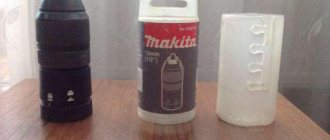
Due to the ingress of dust, dirt and moisture, the internal lubricant becomes hard over time and does not fulfill its purpose. The hammer drill starts to work with extraneous noise. When starting to repair the rotary hammer, be sure to read the attached instructions for disassembling, lubricating, and assembling components of the Makita 2450, 2470 rotary hammer. The diagram of the Makita 2450 and 2470 rotary hammer will help you correctly disassemble faulty components and find defective parts. We will also tell you how to disassemble the Makita 2450 rotary hammer.
Disassembling the Makita 2470 hammer drill begins with removing the mode switch knob.
The procedure for disassembling the hammer drill
Place the hammer drill on a clean surface.
When disassembling the mechanical part of a Makita 2450 or Makita 2470 rotary hammer, you should always remove the mode switch handle.
At the beginning of work, the handle is set to the “Impact” mode (far right position clockwise).
Use a screwdriver to pry up the latch on the handle and remove it.
After removing the latch, the handle is moved to the extreme left position, to the “Drilling” mode.
The handle, clamped with your fingers, is removed from the grooves of the body.
Video instructions for disassembling the mode switch handle of a Makita 2450 hammer drill
Video:
Procedure for setting the mode knob
To install the mode switch into the case, you need to perform some actions: • insert the switch into the “drilling” position into the mounting socket until it clicks; • move the switch counterclockwise to the “blow” position; • turn the switch counterclockwise with a click to the “drilling” position; • insert the spring and the red button; • insert the cover on top until it locks into place. The mode switch is assembled.
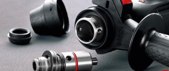
At the second stage, you should disassemble the quick-release chuck and repair the hammer drill chuck with your own hands. By the way, the cartridge requires disassembly only for Makita 2470 models. The design of the cartridge is quite simple, and anyone with a little knowledge of metalworking skills can handle its repair.
Checking with short circuit indicator
You can detect a break in the winding or a short circuit in it using the short-circuit indicator (IR). Other names are an interturn short circuit indicator or an indicator of defects in the windings of electrical machines.
The device consists of:
- power supply;
- housings with an LCD display, sockets for connecting accessories;
- connecting wires;
- large induction sensor;
- small induction sensor.
The procedure for checking the stator of an angle grinder using the IDVI device:
- Inspect the turn-to-turn indicator. Make sure there is no external damage, integrity of connecting wires and sensors.
- Connect the power supply.
- Press the power button and make sure the device is working properly.
- If the winding defect indicator has been in the cold for a long time, then it must be kept at room temperature for at least 2 hours.
- Turn off the power supply to the angle grinder.
- Choose from two sensors, large or small, depending on the size of the stator.
- If the angle grinder's passport does not indicate the rated voltage per winding turn, then it must be determined using the formula: divide the rated voltage of the entire coil by the number of turns.
- Turn on the device.
- Set on the indicator the amplitude of the pulse test voltage that is closest to that obtained in the calculation.
- Pressing the sensor to the surface of the winding, check all the grooves sequentially, waiting 3–4 s. If a short circuit is detected, the device will emit a sound signal and a corresponding message will appear on the display.
- If short-circuited turns are not detected, then set the next (higher value) amplitude on the device and make sure that there is a safety margin for the winding insulation.
- Turn off the device.
The winding defect indicator can be used to check the condition of the insulation between the stator and rotor coils, as well as between the stator winding and the angle grinder body. If it is not possible to buy a ready-made device, then you can make a simpler indicator of short-circuited turns yourself.
The procedure for disassembling the Makita hammer drill chuck
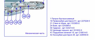
Repairing a hammer drill chuck begins with installing the hammer drill vertically on the back cover of the case. The hrmakita rotary hammer diagram will help you perform disassembly work correctly. Is it necessary to replace the chuck of a Makita 2470 hammer drill? The answer can only be obtained after completely disassembling the cartridge with your own hands. Using a screwdriver or puller, the boot is removed, the cartridge is freed from the retaining ring, the coupling casing, and the metal ring 20 pos.4. Next, you need to carefully remove the ball, pos. 20, remove the guide washer, pos. 5, and the conical spring, pos. 6, that supports it. The cartridge is disassembled.
The diagram below shows the design of a hammer drill chuck.
The main malfunctions of the makita 2450 rotary hammer, causing defects in the operation of the chuck, are:
- wear of the protective rubber boot pos. 1;
- relaxation of the locking ring pos. 2 or its partial wear;
- ball wear pos. 20;
- loss of elasticity of the conical spring pos. 6 or its stretching.
Repairing a hammer drill chuck is not a complicated procedure and is usually easy to do by anyone who can hold a screwdriver.
If replacing a rubber boot, retaining ring, or conical spring is not difficult, then replacing a new ball requires attention. The new ball should have a diameter of 7mm ±1 µm. As lubricants, it is recommended to use a special lubricant designed for Makita rotary hammers. The lubricant has the index Makita P-08361, Makita 183477-5 SDS-PLUS 30g for the gearbox. For drill shanks, it is recommended to use Makita 196804-7 lubricant.
When assembling the cartridge, install the conical spring with its narrow side facing the hammer. Do not forget, repairing a hammer drill chuck with your own hands requires attention from the assembler.
Assembly procedure for quick release chuck
Assembly is carried out on a clean surface. The parts are pre-washed, dried and lubricated with a thin layer of recommended lubricant.
The gearbox shaft is lubricated with Makita 183477-5 SDS-PLUS grease. All incoming parts of the cartridge are assembled onto the shaft in a certain sequence.
Having installed the conical spring pos. 6, put on the guide washer pos. 5 and fix it with the ball pos. 20, inserting it into the groove of the gearbox shaft.
All that remains is to put on the ring pos. 4, the coupling casing pos. 3, and secure the parts with the locking ring pos. 2. At the last stage, insert the protective tip pos. 1 into the end of the chuck. The repair of the Makita 2450 hammer drill chuck is now complete. It remains to check its quality by inserting a drill into the cartridge. When assembled correctly, the cartridge keeps the drill from spontaneously falling out. The cartridge is assembled.
Signs of a fake
Due to the great popularity of the equipment presented, cases of counterfeiting are not uncommon.
There are characteristic features that define a fake HR 2450 hammer drill. These include a short cord (about 0.5 m). The letters on the black clasps of the suitcase are matte on the fake, while those on the original are shiny. In the photo of the hammer drill in the instructions for this product, the background is light gray, almost white. The copy will have a dark, dull color in the background of the image.
If the HR 2450 case shows Japan as the manufacturer, it is not a genuine instrument. The original says: “Made in PRC”, i.e. “made in China”.
The Makita 2450 includes a rubberized handle with a serial number on it. All parts of the suitcase must also each contain its own designation. The fake handle is made not of rubber, but of plastic. This should also be a signal about the need to refuse to purchase such an instrument.
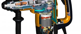
We disassemble the gearbox
To get to the mechanical part, you will need to remove the plastic housing.
The procedure for disassembling the mechanical part of a Makita rotary hammer: First, remove the black protective plastic case. The case is removed after you unscrew the four screws securing the case from the end. By pressing on the end of the shaft you will press the gearbox out of the housing.
After removing the housing, you need to separate the rotor from the gearbox. The gearbox is the general mechanical part. The rotor is separated from the mechanical part (gearbox) simply. You need to clamp the gearbox with your right hand, and clamp the rotor with your left hand. While rocking, pull both parts in opposite directions. The rotor is held in the gearbox by friction of helical gears. The main malfunctions of the Makita rotary hammer occur in the mechanical part of the tool.
The most typical malfunction for the mechanical part is the failure of the impact mechanism.
Disassembling the impact mechanism The impact mechanism is assembled on the inner housing and consists of a gearbox shaft and an intermediate shaft. The rotational motion is transmitted through helical gears to the intermediate shaft.
The gearbox shaft is a hollow shaft in which the cylinder moves freely.
A small spur gear mounted on the intermediate shaft transmits rotation to the large spur gear of the gearbox shaft, in which the impact mechanism is mounted. And translational movements are simultaneously transmitted to the gearbox shaft of the impact mechanism due to transmission from the rolling bearing of the intermediate shaft to the cylinder moving in the gearbox barrel.
Let's move on to disassembling the intermediate shaft.
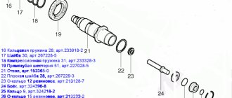
Disassembling the intermediate shaft
Mounted on the shaft pos.40 is a helical gear pos.42, to which rotation is transmitted from the rotor gear, a rolling bearing 608zz pos.41, which transmits translational motion to the hinge pos.34 of the piston pos.32. On the other side of the shaft, a clutch coupling is installed, pos. 39, spur gear 10, pos. 80, compression spring, pos. 38, retaining ring S-7, pos. 37, bearing 606zz, pos. 36. Particular attention should be paid to the condition of the rolling bearings. The hammer drill has imported bearings. Installation of domestic bearings is allowed. Bearing 606zz can be replaced with 80016, bearing 609zz can be replaced with 80019.
Let's move on to disassembling the impact mechanic shaft
Dismantling the impact shaft
Disassembling the barrel of a Makita 2470 hammer drill is a simple process if you use the Makita hammer drill design diagram. The shaft is a barrel, pos. 21, in which the impact mechanism is assembled. A gear, pos. 19, is attached to the barrel, which is pressed by a spring, pos. 18, through a washer, pos. 17, and secured with a retaining ring, pos. 16.
The cylinder, pos. 32, moves in the barrel, acting on the firing pin, pos. 24. A metal ring, pos. 27, is attached to the reverse side of the firing pin, transmitting the blow to the drill. When is it necessary to replace the hammer drill barrel?
Most often the metal ring fails.
Striker
Cylinder with striker
We've sorted out the disassembly.
Replacement
Before disassembling the drill chuck, you need to find out the type of fastening on the shaft: conical or threaded connection. If the thread is left-handed, then manufacturers prudently install a locking screw. It can also be metric or inch.
The conical connection method is formed by using a Morse cone (popularly called instrumental). Installation of the cartridge on such a shaft is carried out with little effort for tightness. This option is often found in the case of screwdrivers.
The table shows a step-by-step algorithm for dismantling drill cartridges.
| Action | Details |
| Threaded connection | |
| Locking screw | Twisting. |
| Cartridge | The way to unscrew the chuck on a drill is counterclockwise using a gas wrench. If necessary, the shaft can be clamped with a vice. Additionally, the device is inspected for serviceability. |
| Jammed drill | You will need a hammer to remove the nozzle. You need to apply several gentle blows from above to the fists. |
| Cone connection | |
| Technically | In order to disassemble the drill chuck, the tool includes a special device. |
| According to folk | The drill is secured with the drill pointing down. The back of the tool is struck evenly with a hammer. In this way, the cartridge is knocked out of the shaft. |
In the case of threads, installation of the cartridge is performed in the reverse order with the same actions as those carried out during dismantling. In the second case, you first need to put the cone in order. Here you will need sandpaper (can be used on fabric) and a file for burrs. After this, the clamping device is also installed using percussive movements, only with a mallet.
Malfunction of stopping the drill when drilling with impact
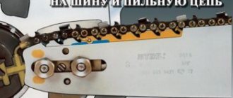
The reasons why a Makita hammer drills with an impact and the drill rotates is due to wear on the teeth of the safety gear and the teeth of the barrel. Often this malfunction occurs when using a rotary hammer as a mixer for mixing mixtures. During operation, the safety clutch slips, and if you take into account the spring load, the load is large.
A visual inspection will not allow diagnosis. You can remove the barrel and secure it in a vice and turn the gear with a wrench, but this can be understood if there is severe wear; in most cases, only disassembling the barrel for diagnostics will help.
Even slight wear of the coupling edges leads to the drill turning and triggering when drilling with impact
Advice on what to do in this case. If it is not possible to remove a suitable part or replace it, then evaluate the wear of the barrel. This is done this way: insert a new drill and move it to the sides; if the play is large, it is better to replace the barrel completely.
It is worth noting that the reason for the drill turning when drilling with impact can be:
- wear of the shaft bearings;
- the gear near the drunken bearing can be licked.
Video:
On sale, if you search, you can buy a gearbox assembly for a hammer drill and its cost is about 2000 rubles.
The reliability of some sellers is questionable, and if you consider that these are often spare parts taken from analogue tools that are sold, for example, on Avito. How to distinguish a fake hammer drill from an original one.
For example, there are many Chinese hammer drills similar to Makita. An example is a network hammer drill FAVOURITE RH 950 and its cost in the aisle is 3000 rubles. which is profitable to sell for spare parts.
The Favorit hammer drill is an analogue of the Makita 2450
We replace the parts with serviceable ones and get ready to assemble. Learn more about lubrication and assembly of the hammer drill.
Read if there are problems with the electrical part of the hammer drill.
How to repair a Makita HR 2450 rotary hammer if the shock mode has disappeared – Man in the House.Ru
Makita power tools have long established themselves as professional, reliable and easy to maintain. In addition, it has good maintainability and a relatively low price.
Of all the lines of rotary hammers, I would like to focus on the Makita HR 2450 . The tool is very easy to use, has three operating modes and can withstand very long loads. The author of these lines worked faithfully and faithfully for more than six years without any breakdowns. Moreover, it was used under intense loads. But one fine moment...
The hammer blow has disappeared - what to do?
As you know, nothing lasts forever. And reliable equipment breaks down. Somehow, in the midst of work, he stopped hammering. The machine was working in rotation mode, but the shock suddenly disappeared.
The gearbox was disassembled and the cause of the breakdown was identified. The bushing in the barrel body, in which the firing pin directly carries out the impact work, was broken. As a result, the striker became jammed in the fragments of the collapsed bushing.
The service center advised to replace the barrel completely. It turned out that the bushing is pressed into the barrel at the manufacturer and is not supplied separately. I had to buy a whole new barrel.
In this article we will tell you how to put the hammer drill into working condition yourself after this, in general, simple breakdown. If you have the skills to repair power tools and the desire not to pay someone your hard-earned money, then we take the tool and start disassembling the machine.
Tools
You will need two ordinary flathead screwdrivers and one Phillips head screwdriver. One of the flat-head screwdrivers should be thin and narrow, no more than 4 mm wide. You will also need a wire hook to remove the retaining ring. It can be made from a bicycle spoke, the main thing is that the wire is rigid and does not bend easily. You will also need a rubber mallet or wooden mallet.
Types of brushes
There are several classes of brushes that satisfy different switching conditions:
- Graphite brushes. They are made on the basis of graphite with the addition of filler in the form of soot and other substances. Brushes are intended for light commutation in generators and engines. The grades EG61A and G20 are produced.
- Carbon-graphite type. Low strength brushes for light mechanical loads. Brands G21, G22.
- Electrographite type. Brushes of increased mechanical strength, saturated with carbon. Perform switching of medium complexity. Withstand high current loads. There are brands EG2A, EG74, EG14, EG4, EG841.
- Metal-graphite type (copper-graphite brushes for electric motors). The main component of the brush is copper, tin and graphite powder. They come with different fillers. The brushes are highly durable and do not allow gas or liquid to pass through. Applicable in high and medium complexity switching conditions. Ensure the functioning of low voltage generators. The brands are MG, MGS, MGS 5, MGS 20, MGS 51, MGSOA, MGSO, MGSO1M, M1A, M1.
The described brush contacts are applicable in industry; brushes of the G33MI, G33, G30, G31 brands are produced for household equipment.
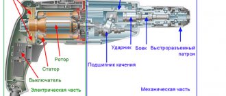
Operating principle and design of an AC synchronous electric motor
This type of electric motor is used in everyday life where a constant rotation speed is required, the ability to adjust it, and also if a rotation speed of more than 3000 rpm is required (this is the maximum for asynchronous ones).
Synchronous motors are installed in power tools, vacuum cleaners, washing machines, etc.
In the housing of an AC synchronous motor there are windings (3 in the figure), which are also wound on the rotor or armature (1). Their leads are soldered to the sectors of the slip ring or collector (5), to which voltage is applied using graphite brushes (4). Moreover, the terminals are located so that the brushes always supply voltage to only one pair.
The most common breakdowns of commutator motors are:
Principle of operation. The torque in an electric motor is created as a result of the interaction between the armature current and the magnetic flux in the field winding. With a change in the direction of the alternating current, the direction of the magnetic flux in the housing and the armature will also change simultaneously, due to which the rotation will always be in one direction.
The rotation speed adjustment is changed by changing the amount of applied voltage. In drills and vacuum cleaners, a rheostat or variable resistance is used for this.
Changing the direction of rotation occurs in the same way as with DC motors, which I will talk about in the next article.
Source
Check and enable
Before starting the engine for the first time after repair, it must be thoroughly checked. To begin with, all inserted “coils” ring. This will help you find out if there is a break or poor contact. The resistance is measured between the “layings” so that a short circuit does not occur when turned on.
You should not immediately supply 220 V to the engine; it is better to supply a reduced voltage. Let the rotor spin slowly, the main thing here is to find out if the engine is overheating. If everything went well and no smoke appeared, then the engine repair was successful.
There are many photos on the Internet on rewinding motors. This will help beginners visually familiarize themselves with the process.
Why thousands of customers have already chosen us
Experience reliability guarantee
- On the market since 2002
- More than 1000 customers have already chosen us
- Own production and extensive relationships with suppliers
- Significant stock of warehouse products
- Dealer discounts
Production price selection
- All types of brushes for electric motors can be purchased from us
- Selection of brushes by brand of electric motor and brush holder
- Production according to GOST
- Full compliance with technical parameters
- Flexible discount system
- Selection of domestic and imported analogues
Process work result
- Assigning a personal manager to each customer
- Technicians have advanced degrees
- Shipment by any type of transport to anywhere in the country
- Reliable product packaging
We have been producing electric brushes for electric motors for 12 years.
Complex supplies of electrical equipment from TPK "Electromashina" are an effective connection between the Client and the Manufacturer. Our company strives to provide the most convenient conditions for cooperation and stable product quality. Our close partnership with the largest companies in Russia and the CIS allows us to significantly reduce the cost of products from well-known and time-tested manufacturers, as well as guarantee optimal delivery conditions in terms of price-quality ratio. All this makes our prices the most favorable for the consumer.
Stator protection with thermal relay
During operation, the electric motor may consume increased current from the network and experience strong heating. The reasons may be different, for example, too much load on the shaft, frequent turning on and off of the motor, increased ambient temperature. Such abnormal operating conditions can lead to overheating of the stator windings and their failure. To prevent damage to the electric motor, one or two bimetallic thermal relays are installed in the stator system - these are thermal switches called klixons.
Klixon thermal switch
When the stator temperature rises above the set value, the bimetallic klixon contact opens. The thermal switch opens the power supply circuit to the control coil of the power contactor, which supplies voltage to the electric motor. The contactor disconnects the electric motor from the power supply. Further switching on of the contactor and, therefore, the electric motor is possible only after cooling the stator windings and closing the bimetallic pair of the thermal switch.
Wire winding
There are several ways to rewind the stator of an asynchronous electric motor, but when choosing any of them, be sure to remember each step during disassembly. This will make the repair easier, and significantly. For winding, you will need a copper wire in varnish insulation; its cross-section should be the same as on the electric motor being repaired.
Make sure that there is no damage to the housing and magnetic circuit of the electric motor. After this, it is necessary to make sleeves and install them in the grooves on the stator. In order not to count the number of turns, or to determine the thickness, strength and heat resistance of materials for the manufacture of sleeves, you can use reference literature. To do this, you need to know the type and model of the asynchronous motor.
All work in specialized workshops is carried out on machines. The machine even calculates the number of turns. But how can you rewind an electric motor at home if there are no such conditions? You will have to calculate everything yourself, or take all the data from the service book for the electric motor.
Connection diagram for a drill button with speed control and reverse
The actual visual connection diagram is shown in the image below.
Let me give you a few clarifications.
- The picture shows the most common type of spare part in question. The electrical wires from the power plug are fastened to terminals that are bolted. The rest are stuck into self-clamping contacts. If your button is not like this, then it is better to make notes from the old copy of what is attached where. Also, a diagram can be drawn on the body itself, which can also be used to guide you.
- If you connected the capacitor as described above, then after connecting the wires from the plug, you will only have two contacts on the bottom of the case, where you need to plug in two cables from the stator. They usually have the same position on the stator as in the picture. Their length must be longer than the other two so that they can reach their clamps. In this case, it makes no difference which wire is plugged into which of the two contacts.
- The remaining two electrical wires from the stator, as well as cables from the brushes, are connected to the reverse terminals. In this case, the connection is made diagonally: the wires from the stator are stuck on opposite sides into diagonally located contacts; and from brushes too. At the same time, the only direction in which the cartridge will rotate at a certain position of the reverse trigger depends on where exactly the wires will be inserted. The main thing is to connect diagonally.
This is the connection diagram. I hope that you will be able to connect everything correctly and the drill will work as it should.
Of course, it is impossible to state so unequivocally that the buttons on all drills are connected the same way, there are drills with reverse, there are direct connections, so this answer will be more introductory than carrying specific information.
Even on drills of the same type, there is a difference in connecting the button depending on the functionality of the drills; here is an example of connecting an old Soviet drill:
Another connection diagram for a drill with reverse, more or less generally accepted:
On some reverse drills, the following contacts are used on the button:
The top of the button interrupts the pole on the electric motor.
There can be a different number of sockets (wires) for switching the drill button, depending on the functionality of the tool, but at least six - two - network input 220 (phase + zero) - two going to the capacitor and two going to the winding and stator brushes of the electric motor.
How to repair asynchronous motors
If there are problems in the engine, then these are problems of either a mechanical or electrical nature. In the first case, a breakdown may be accompanied by strong vibration and characteristic noise. This usually indicates a bearing problem - usually in the end cap. Failure to repair the breakdown in time can result in the shaft jamming, and as a result, the stator windings will fail. At the same time, the thermal protection function of the circuit breaker may not have time to operate.
Practice shows that in approximately 90% of malfunctions of asynchronous motors, problems appear in the stator winding - in the form of a break, an interturn short circuit, or a short circuit to the frame. At this time, the short-circuited armature most often continues to function properly. Thus, if engine damage has a mechanical cause, the electrical part must be checked.
Most often, the problem can be identified by external signs and a characteristic odor (Fig. 1). If the breakdown could not be detected empirically, then we resort to diagnostics and make a continuity test for a break. If we find it, we disassemble the motor (we will talk about this in more detail later) and carefully inspect the connections. When no defects are found, we can say that we have a break in some coil. Therefore, you need to rewind.
If after testing the break is not detected, then we measure the resistance of the windings, taking into account the following nuances:
• it is necessary that the insulation resistance of the coils on the housing tends to infinity; • it is necessary that the windings of a three-phase drive show the same resistance; • it is required that for single-phase models the resistance of the starting coils exceeds these parameters of the operating windings.
You also need to remember that stator coils have very low resistance. Therefore, to measure it, there is no point in using devices that have a low accuracy class - this is the majority of multimeters. The issue can be solved if you assemble a simple circuit using a potentiometer, adding an additional power source - for example, a car battery.
How to take measurements:
• connect the drive coil to the circuit presented above; • use a potentiometer to set the current to 1 A; • calculate the coil resistance using the following formula: where R K and U PIT are described in Fig. 2. R – resistance of the potentiometer, – voltage drop across the measurement coil (shown in the diagram by a voltmeter).
Daily care and storage
In order for the tool to serve the master properly for many years, during operation it is recommended:
run the device “idle” before starting work
If the hammer drill shows signs of breakdown, work is stopped and diagnostics begin. After completing the work, take care of the cleanliness of the rotary hammer - it is important to remember that electrical appliances “do not like” water; cleaning is carried out with a vacuum cleaner and rags. If the hammer drill is working in the cold or has been moved indoors from outside, do not start it right away. Allow the components to “warm up” and the lubricant to thaw. Carry the hammer drill in a special box or suitcase (usually included) to avoid dust and construction debris.
Thus, if you follow objective precautions and operating rules for the hammer drill, it will last a long time and without breakdowns. If trouble does happen, the suggested advice from the experts will help determine the essence of the problem and promptly fix the breakdown.
When drilling holes with a hammer drill, the main factor is not the rotation of the drill, but the impact. Both the drilling speed and the ability of the tool to cope with particularly hard building materials (concrete, granite and others) depend on its strength.
Dust and constant loads on the tool negatively affect its performance. During operation, the impact force may noticeably decrease or disappear completely.
How does a hammer drill work and why does it “refuse” to hammer?