How to choose a replacement belt?
Before replacing an old belt with a new one, you must select it correctly. When choosing from an online store, pay attention to the following criteria:
- Manufacturer.
- Lawn mower model.
- Belt type: V-shaped, poly-V-ribbed, toothed.
- Compatibility (usually indicated in the description if it is analog).
- Original belt number.
- External resemblance.
If you find it difficult to choose the right belt for your lawn mower model, contact a consultant.
General principles and rules for replacing a lawn mower belt
Drive belts in lawn mowers are used both to drive the cutting blades and to transmit torque to the drive wheels in self-propelled models. If it becomes necessary to replace this part, adhere to the following general rules and principles:
- Take precautions - turn off the engine and wait until the blades stop completely.
- Unplug the electric lawnmower.
- On gasoline engine models, remove the spark plug.
- To replace the lawn mower's drive belt, you must gain access to the bottom of the mower.
- Models with gasoline engines may be turned over on their side so that oil does not get into the carburetor and air filter.
- Before removing the drive belt, fix its position relative to the tension and limit rollers (take a photo or sketch it).
Whenever possible, follow the recommendations from the official instructions for your lawn mower. The information provided below is for informational purposes only.
Mechanical malfunctions of makita 2450 and makita 2470 rotary hammers
Common mechanical malfunctions of Makita rotary hammers include:
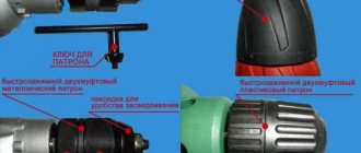
- destruction of the quick release chuck;
- bearing failure;
- damage to the impact mechanism;
- wear of the hammer drill barrel;
- wear of the rubber striker and striker;
- gear failure.
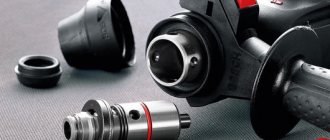
Repair of a hammer drill chuck is carried out to replace the boot and rubber ring, as well as a conical spring and a steel ball that clamps the working tool (drill). This is indicated by the fact that the working tool? namely the drill, is poorly held in the chuck.
The main reason is wear of the steel ball 7.0 pos. 20, art. 216022-2. Ball wear occurs from contamination of the cartridge bore due to dust and dirt getting inside.
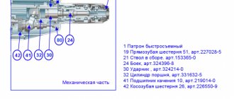
The general view and design of the Makita hammer drill chuck is shown in the photo below.
Repairing a makita 2450 hammer drill chuck with your own hands is easy. The cartridge must be disassembled, freed from old grease, discarded rubber parts, and replaced defective ones.
More complex faults require knowledge of the mechanical structure of the Makita 2450 rotary hammer.
Having determined the nature of the malfunction of the Makita rotary hammer, proceed to disassembling the mechanical part, called the gearbox.
Disassemble the mechanical part according to the attached video. Free it from old grease. Carefully inspect all parts, their integrity, and level of wear. All rubber products require replacement during any disassembly.
Let's consider repairing a hammer drill barrel. Let's analyze the mechanism completely. Video of disassembling, lubricating and assembling a Makita hammer drill
Features of replacing the V-belt
V-belts are the most common on household rotary-type self-propelled lawn mowers. Their replacement and adjustment is carried out according to the following algorithm:
- Place the mower on its side for easy access to the drive.
- Remove the drive mechanism protection by unscrewing the screws or releasing the latches.
- Remove the belt retainer near the drive pulley.
- Unscrew the knife fixing screw.
- Carefully remove the knife.
- Remove the driven pulley from the shaft along with the belt.
- Place a new V-belt onto the drive shaft.
- Having first put the belt on the driven pulley, install it on the shaft.
- Place the knife in its place and secure it with a screw or nut.
- Reinstall the belt lock.
In such designs, adjustment of the lawn mower drive belt is usually not provided.
Features of replacing and adjusting the poly V-belt
Some models of lawn mowers use poly-V-ribbed or so-called ridge drive belts. They are distinguished by their high efficiency of torque transmission, and therefore are usually installed on pulleys with a relatively small diameter. Poly V-belts are found in professional lawn mowers designed for long-term and variable loads. They are also common on many battery models.
Replacement and adjustment are performed according to the following algorithm:
- Position the lawnmower so that you can access the drive mechanism.
- Remove the screws that secure the guard to the rear of the mower.
- Unscrew the cutting attachment mount.
- Unscrew the belt tension roller fixing nut.
- Remove the belt from the drive mechanism.
- Install a new belt in the reverse order of disassembly.
- Check the belt tension.
- If it sags by more than 4-5 mm, loosen the tension roller bolt and achieve a stronger tension.
- Make sure that the new belt does not touch any parts of the mower body.
- Reinstall the cutting attachment and protective guards.
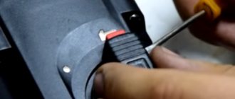
drill button with regulator
After each use, you need to carefully clean the rotary hammer from dust. With a soft cloth or napkin you should wipe not only the body of the power tool, but also the ventilation slots.
It is unacceptable to use a hammer drill outdoors during periods of rain and snow.
Carbon brushes, which are an important part of the electrical circuit, should often be inspected - they conduct current to the commutator and, during use, wear out evenly and require replacement.
It makes no sense to take non-original components of unknown properties, which lead to more significant breakdowns.
Source
Features of replacing and adjusting the timing belt
Timing belts in electric lawn mowers are most often mounted on two pulleys. One of them is located directly on the motor shaft, and can move with it after the fasteners are loosened. The driven pulley is usually stationary. To replace the timing belt in such a lawn mower, you must follow these steps:
- De-energize the instrument.
- Position the lawnmower so that the drive mechanism is easily accessible.
- Remove the protective cover.
- Loosen the screw that secures the motor and the drive pulley on it.
- Slide the drive pulley toward the driven pulley to release the belt tension.
- If the belt is torn or missing, still follow steps 1-5.
- Place the new belt on the drive pulley first.
- Throw the belt over the edge of the driven pulley and, turning the drive mechanism, ensure that the belt is completely installed on the driven pulley.
- Move the motor with the drive pulley to its original position to tighten the belt.
- Tighten the fixing screws.
- Check the belt tension - it should not sag by more than 4-5 mm.
- If necessary, tighten or loosen the belt by first unscrewing and screwing back the motor fixing screws.
After replacing and adjusting the lawnmower belt, reinstall the guard.
Disassembling the Barrel of the Makita 2450 Rotary Hammer
Makita 2450 hammer drill diagram
Content
Do-it-yourself repair instructions for a Makita 2450 rotary hammer
Hammers are impact drilling devices designed for drilling and chiseling holes in particularly strong materials. The hammer drill implements two ideas: the working tool rotates and immediately moves longitudinally, creating a shock impulse.
Rotary hammers always operate under extreme conditions. The operating life of rotary hammers depends not only on the correct operating conditions, but also on the reliability of the parts included in the product.
But no matter how hard you try, over time the hammer drills begin to fail.
In order to properly repair a rotary hammer, you need to study its structure. Repair of the Makita 2470 and 2450 rotary hammer can be carried out independently by a person who has the skills of a mechanic and understands the basics of electrical engineering.
Remember! Follow safety rules and disconnect the hammer drill from the mains when disassembling.
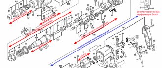
The Makita 2450 and 2470 rotary hammers are assembled according to virtually a similar design and from the same parts. Repairing them is no different. For ease of repair, below is an assembly diagram and a catalog of parts for Makita rotary hammers.
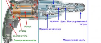
The Makita 2450 and 2470 rotary hammer circuit consists of a mechanical and electronic part.
The mechanical part ensures the transmission of torque to the drill bit, immediately creating a translational movement that creates an impact. The mechanical part consists of a rotation drive and an impact mechanism.
The electronic circuit of the Makita rotary hammer ensures the conversion of electronic energy into kinetic energy through the rotation of the rotor. The electronic part includes an electric motor, a power button with a speed controller, a reverse switch, and connecting wires. The main malfunctions of a makita rotary hammer. Malfunctions of rotary hammers are divided into electronic and mechanical.
Next, we will look at our client’s problem with the electronic part of the Makita 2470 and 2450 rotary hammers and methods for eliminating them:
Electronic malfunctions of the Makita 2450 and Makita 2470 rotary hammers Electronic malfunctions appear in such a way that when the rotary hammer is connected to the mains voltage, the tool does not turn on. The connection diagram for a Makita hammer drill to the network is ordinary.
The electronic circuit of the Makita 2450 rotary hammer is essentially a serial connection of an electric motor, a start button and wires. The Makita 2470 rotary hammer circuit is similar.
Through the connecting cord pos. 72, the 220 V supply voltage is supplied through the switch pos. 68 and the electronic brushes through the brush holder pos. 66 to the lamellas of the electric motor rotor pos. 54, and through the contacts of the reverse switch pos. 60 to the stator winding pos. 59. The most common malfunction is the lack of contacts in the connections.
Procedure for identifying electrical faults
Video: Makita HR 2470 disease \ Rotary hammer 2470 has finished cutting in \ Contacts are burnt \ maintenance tool
Determining the integrity of the electronic part of a Makita hammer drill. If you set a goal to repair a Makita 2450 or Makita 2470 hammer drill yourself, you need to arm yourself with devices and equipment. Any tester, a set of screwdrivers, keys, a hammer, or a wooden adapter will do. It's great to have a screwdriver with an integrated phase indicator.
You need to take a tester, connect to the ends of the hammer drill plug and press the hammer drill switch. If the tester indicates some resistance, then the power supply circuit of the hammer drill is intact.
If the tester indicates infinity, then the integrity of the circuit is broken and it is necessary to remove the back cover to check the connecting cable and electric brushes of the hammer drill.
The back cover (usually dark in color) of the hammer drill is easily removed; you just need to remove three screws using a screwdriver or a screwdriver.
Remove the cover and use a screwdriver to disconnect the ends of the wires from the electric brushes. Using a tester or a homemade device, also called a “hopper,” determine the integrity of the supply wires and the correct operation of the switch.
A few words about an ordinary control device called “arkashka”. The device consists of an LED or a light bulb from a flashlight, a AA battery and two pieces of wire. The entire electronic circuit of the control device is alternately connected parts. Connect the battery to one end of the LED, or light bulb, and connect the wires to the free ends of the LED and battery. You will get a universal device for checking the integrity of electronic circuits.
Corresponding malfunctions of the Makita 2450 and 2470 rotary hammers Common malfunctions in the electronic part of the Makita 2450 and Makita 2470 rotary hammers:
- fracture of the supply cable at the entry point into the hammer drill;
- breakage of the switch button TG813TLB-1, art. 650508-0, pos. 68.;
- wear of electronic carbon brushes SV-419, art. 191962-4, pos. 65;
- wear of reverse switch contacts;
- wear of rotor bearings: bearing 609LLU, art. 210060-6, pos. 51; bearing 607LLU, art. 211021-9, pos. 56;
- short rotor closure 220-240 V, art. 515668-8, pos. 54;
- breakdown of the stator winding 220-240 V for HR2450, art. 633488-5, pos. 59.
For the start button, use the TG813TLB-1 switch, art. 650508-0; pos. 68.
Replacement of brushes is done when they are completely worn out or have poor contact. This malfunction is detected by strong heating of the points where the electric brushes are installed.
The failure to turn on the hammer drill is caused by abrasion of the contacts on the reverse switch. This type of problem is painfully easy to fix.
Repair of Makita rotary hammer reverse switch
When repairing the reverse switch, you need to disconnect the back cover. Carefully disconnect the wires from the button. Take a close look at the switch.
The upcoming disassembly involves removing the brush holder, having previously freed the brushes themselves. By removing the brush holder, you will get to the reverse switch contacts.
Determine its condition, change contacts if desired.
An additional, often encountered electronic malfunction is poor contact between the stator and the lower contacts of the reverse switch.
Repair of contact between stator and reverse switch
To remove the stator, you need to disconnect the gear housing (dark color) from the stator housing (greenish color).
Remember! In the mechanical part of the rotor, the bearing is pressed by a special ring. Don't lose it when disassembling.
The stator is located in the greenish housing. Having visited the middle, you will see two self-tapping screws 4x60, art. 266334-3, pos. 57, securing the stator to the housing. Unscrew them, remove the plastic stator protection for HR2450, art. 419201-3, pos. 58., release the stator. When you remove the stator, you will see the contacts on the stator and the reverse switch panel.
READ Now You No Longer Need To Cut Birch Trees
Carefully clean the contacts with sandpaper and treat with solvent or alcohol.
Before assembly, bend the contacts so that they fit tightly into each other. Lubricate the contacts with a thin layer of technical Vaseline.
Assembling the electronic part of the hammer drill is done in reverse order.
Instructions for disassembling the Makita 2450 rotary hammer
A hammer drill is an impact drilling tool that simultaneously performs the function of impact and drilling equipment when working with particularly strong materials.
The device uses two ideas at once: the tool rotates and moves longitudinally, transmitting the impact impulse to a hard surface.
Rotary hammers always operate in extreme environments with the highest degree of dust.
The duration of trouble-free operation is influenced not so much by the operating conditions, but by the quality of the components included in the tool.
Makita 2450, 2470 rotary hammers are reliable tools for high-quality work. Even the most reliable tool requires proper care and timely maintenance.
To perform maintenance of Makita 2450, 2470 rotary hammers, you must become familiar with the internal contents of the tools included in the components. A real summary will help you find out the weak points of the Makita rotary hammer.
To repair a Makita 2450, 2470 rotary hammer in a home-made environment, a person with plumbing skills and knowledge of electrical engineering is allowed.
Remember! When repairing a rotary hammer, you must follow safety rules when working with electrical appliances.
The Makita 2450 and 2470 rotary hammers are assembled according to virtually a similar design and, in fact, from similar, interchangeable parts. Repairing them is no different.
View of the Makita 2450 rotary hammer
For ease of repair, below is an assembly diagram and a catalog of parts for Makita rotary hammers.
Makita 2450 rotary hammer assembly diagram
Design of Makita 2450 and 2470 rotary hammers
The Makita rotary hammer conventionally consists of electronic and mechanical parts. At the same time, the mechanical unit of the hammer drill is housed in a dark-colored plastic case, and the electronic part of the hammer drill is hidden under the greenish plastic case.
The procedure for disassembling the mechanical part of the hammer drill
The mechanical unit is designed to transmit the rotational moment of the shaft to the tool, creating not so much a torque and a translational impact impulse.
The task of the mechanical unit is to transmit rotation from the rotor to the tool, simultaneously providing the tool with longitudinal movement.
Disassembling the hammer drill begins with removing the quick-release chuck.
Quick Release Chuck Parts
Having disassembled the cartridge, unscrew the four screws, pos. 10, fastening the gear housing cover, pos. 14, of the mechanical unit and the hammer housing and, pressing on the end of the hammer shaft, remove the black plastic cover.
Removing the cover of the mechanical unit
To remove the mechanical unit from the greenish stator housing, you need to:
- 1. Remove three screws, pos. 70, 75, 76, holding the cover, pos. 69, in the hammer handle;
- 3. Having released the springs of the brush holders pos. 63, 66, take out the carbon brushes pos. 65.
Now you can remove the mechanical unit from the stator housing.
Type of mechanical block
Having freed the mechanical unit, you need to disconnect the rotor from it. Rotor pos. It is attached to the mechanical block by friction of the gear teeth and is pulled out by shaking and disconnecting immediately.
Disassembling the mechanical block of the shock assembly
The mechanical unit is assembled on the inner housing, pos. 49. To remove the intermediate shaft, you need to unscrew two bolts, pos. 43, at the base of the housing. The intermediate shaft is also fixed with a mode switch lever.
Two words about the mode switch
The Makita 2450, 2470 rotary hammers have a lever that provides the tool with three operating modes. A hammer drill can simply drill, simply chisel, and chisel with simultaneous drilling. The switch lever is placed on the axis of the inner housing and is fixed with a compression spring pos. 85, a washer pos. 87 and a retaining ring pos. 86.
It's time to remove the intermediate shaft.
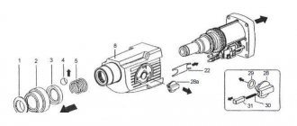
Dismantling the intermediate shaft
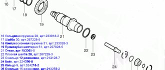
To disassemble the intermediate shaft, use the diagram attached to this annotation.
Photo of the intermediate shaft diagram indicating the disassembly order
Remove everything from the shaft pos. 40 in order:
- A). bearing pos. 46 and ring pos. 47;
- b). spur gear pos. 42;
- V). rolling bearing pos. 41;
Do-it-yourself repair of the Makita HR 2450 rotary hammer gearbox. the most complete review
I got to my own makita hammer drill
HR
2450
, which has lost its blow, is at its peak. The internal blow meets, and on the pike.
Disassembling the Makita HR 2450 rotary hammer
This Video. Part 1 of the Makita hammer drill
HR
2450
alone.
And today remove the shaft:
- G). flat washer 12 pos.35;
- d). bearing 606 pos.36;
- e). retaining ring S-7 pos. 37;
- and). compression spring 7 pos. 38;
- h). clutch coupling pos. 39.
The procedure for disassembling the barrel shaft of the impact mechanism
To disassemble the impact mechanism shaft, you need to remove it from the inner housing.
From the shaft you need to remove the cylinder pos. 32, inserted into the internal cavity of the shaft.
The cylinder can be disassembled very easily:
- 1. With its use, you need to get the firing pin, pos. 30;
- 4.5. The piston hinge pos. 34 is knocked out;
- 3. Remove two flat washers pos. 33, 35.
To disassemble the shaft itself, position 21 of the impact mechanism, you need to remove the unfamiliar cartridge mounting shaft:
- — ring spring 28 pos. 16;
- — washer 30 pos. 17;
- — compression spring 31 pos. 18;
- — spur gear 51 position 19;
- - metal ball 7.0 pos.20.
And those not familiar with the internal cavity of the shaft need to be removed:
- — ring spring 28 pos. 29;
- — rubber ring pos. 28;
- — iron ring pos. 27;
- — rubber ring 15 pos. 26;
- — ring 9 pos.25;
- - flat iron washer 28 pos. 22.
Disassembled barrel shaft
Disassembling the electronic part of the Makita 2450, 2470 rotary hammer
The electronic part of the Makita 2450.2470 rotary hammer includes:
- switch TG813TLB-1 pos.68;
- carbon brushes SV-419 pos.65;
- brush holder pos. 63,66.
To remove the stator, simply tap on the end of the plastic greenish housing of the unknown stator with a wooden mallet or with another block.
But first you need to unscrew two self-tapping screws 4x60 mm pos. 57.
With frequent tapping on the housing, the stator spontaneously protrudes beyond the edges of the housing and is then removed by hand.
Other elements of the electronic part of the Makita 2450 or 2470 rotary hammer can be easily dismantled, since they are not attached to anything.
Disassembly of the hammer drill is completed.
Makita 2450 rotary hammer disassembled
How to lubricate and assemble the Makita 2450 and 2470 hammer drill correctly
The assembly of any mechanism should begin after painstaking preparation. It is necessary to prepare not only the parts, but also the tools, space, and lubricant.
READ How to Insert a Whisk into a Hammer
Among the tools, you can’t do without pliers, screwdrivers, a hammer, and a brush for applying lubricant.
What is the assembly diagram for the Makita 2450 and 2470 rotary hammer?
Assembling the Makita hammer drill yourself, you will like it, is carried out only on the terms of compliance with the attached instructions.
The task of the assembly process is to replace worn-out parts with suitable ones and ensure the interchangeability and operability of the tool.
Assembly procedure for the Makita 2450 rotary hammer
Impact mechanism assembly
How to assemble the impact mechanism of a Makita rotary hammer? The impact mechanism is assembled from two units: a barrel shaft with a spur gear and an intermediate shaft with a rolling bearing.
A). A spur gear, pos. 19, is put on the barrel, pos. 21, and pressed by a compression spring, pos. 18. To fix the spring, it is pressed with washer 30, pos. 17, and secured with retaining ring 28, pos. 16.
B). To assemble the striker, you need to put ring 9, pos. 25, on the striker shaft, tighten the rubber ring, pos. 26, and press it with the iron ring, pos. 27.
Now we move to the back side of the barrel, pos. 21. At the same time, the inner surface of the barrel must be lubricated with grease and the assembled firing pin, pos. 24, must be inserted inside.
Assembling the intermediate shaft and piston
Assembling the intermediate shaft assembly
To assemble the intermediate shaft, you need to put the rolling bearing pos. 41 on the shaft pos. 40 with the teeth to the shaft splines, and put the coupling pos. 39 on the shaft splines.
Translation of translational motion
On the reverse side of the shaft, a helical gear 26 pos. 42, a flat washer 8 pos. 45, a bearing 608zz pos. 46 and a retaining ring 8 pos. 47 are put on. The intermediate shaft is assembled.
Assembly of the gearbox assembly
The production of the gearbox unit is made on the internal housing, pos. 49.
When, there are cases when the axles jump out of the inner duralumin housing. Both axles are pressed into the housing.
The assembled intermediate shaft is inserted into the housing, pos. 49, the rolling bearing arm of which must fit into the hole in the cylinder hinge.
In this case, the rolling bearing lever, pos. 41, of the intermediate shaft must fit into the cylinder hinge, pos. 32, and the lower bearing of the intermediate shaft into the socket in the housing. This function is usually done by rocking the structure until the parts completely fall into the designated places.
Installing the mode switch lever
The mode switch is designed to move the clutch, pos. 39, to different positions and transmit translational motion to the shaft of the impact mechanism through the rolling bearing, pos. 41, to the cylinder, pos. 32.
Assembly of the mode switch lever for the Makita 2450 rotary hammer
On the axis of the inner housing you need to put the mode switch lever pos. 82 on top, press the pressure spring pos. 88 on top, and press it with a flat washer pos. 87. Install the locking ring pos.86. and fix it. The locking ring must be carefully fixed. When turning the intermediate shaft, you need to carefully check the correct operation and free movement of the cylinder in the housing. This needs to be done at the moment so that it does not become clear at the end of the assembly that the assembly was assembled incorrectly.
Impact shaft assembly
First you need to lubricate the inside of the cylinder, pos. 32, and insert the hammer, pos. 30, there.
It remains to place the lubricated barrel assembly, pos. 21, in the inner housing, pos. 49, to the area, putting it on the lubricated cylinder, pos. 32. For lubricants, it is recommended to use a special lubricant designed for Makita rotary hammers.
Lubricants are available in several types: Makita P-08361 and Makita 183477-5 SDS-PLUS.
Makita 183477-5 SDS-PLUS lubricant is recommended for the gearbox. For drill shanks, Makita 196804-7 lubricant is used.
Lubricants vary in color, but have completely similar features. In addition, what lubricants are used in the Makita 2450 and 2470 hammer drills?
And here we have the assembled mechanical unit.
Video of general disassembly and assembly of the Makita 2450 rotary hammer
Check its performance by rotating the intermediate shaft and monitoring the movement of the piston in the impact mechanism. It remains for our client!
Now let’s lubricate what remains to be done for our client, the parts of the mechanical unit with the recommended lubricant. Here is a clear example of how to properly apply lubricant to rotating surfaces. But another example of generous lubrication of a mechanical unit.
You can't spoil porridge with oil
This way it is also possible to apply lubricant. You can't spoil porridge with oil!
The lubricated mechanical unit must be covered with a dark-colored plastic case, pos. 14. Having placed the housing on top of the assembly, press the housing down until the assembly is securely secured in the personal computer. The backwardness is to insert four bolts, position 10, into the body and tighten.
Now it’s time to attach the electric motor rotor to the mechanical part. Rotor installation
The helical rotor gear is tightly inserted into the body of the mechanical unit and pressed.
All that remains is to insert four self-tapping screws m4x60 pos.57. and screw them into the electrical unit housing.
Installation of electric brushes
Remove dirt from the grooves of the brush holder and install the brushes to the area, securing them with latches.
Now is the time to check the functionality of the hammer drill. Connect the plug of the hammer drill to the socket, turn on the hammer briefly while working in the “drilling” mode. Once you are sure the tool is working, turn it off. Set the mode switch to the “impact” position. Do not stick the tool in. Check the functionality of the hammer drill in this position. At the same time, you checked the operation of the mode switch.
All that remains is to check the placement of the speed control button, make sure the contact connections are reliable, and you can begin installing the expensive cover.
The cover is secured with 3 self-tapping screws M×4 of different lengths.
Connect the hammer drill to the 220Β network and check in all modes. The Makita 2450 rotary hammer, or 2470, is assembled and working properly!
How to repair the cartridge and impact mechanism of the barrel of a makita 2470 hammer drill
Due to the ingress of dust, dirt and water, the internal lubricant becomes harsh over time and does not even serve its purpose. The hammer drill starts to work with extraneous noise. When starting to repair a rotary hammer, be sure to read the attached instructions on disassembling, lubricating, and assembling components of a Makita 2450, 2470 rotary hammer. The diagram of a Makita 2450 and 2470 rotary hammer will help you correctly disassemble faulty components and find defective parts. In addition, we will tell you how to disassemble a Makita rotary hammer 2450
.
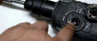
Disassembling a Makita
The 2470 starts by removing the mode selector knob.
The procedure for disassembling the hammer drill
Place the hammer drill on a clean surface.
When disassembling the mechanical part of a Makita 2450 or Makita 2470 rotary hammer, you should always remove the mode switch handle.
At the beginning of work, the handle is set to the “Impact” mode (far right position clockwise). Use a screwdriver to pry up the latch on the handle and remove it. After removing the latch, the handle is moved to the extreme left position, to the “Drilling” mode. The handle, clamped with your fingers, is removed from the grooves of the body.
READ How to choose a good cordless screwdriver for your home
Video instructions for disassembling the mode switch handle of a Makita 2450 hammer drill
Video: How to install\ How to remove the mode switch on a Makita HR 2450 rotary hammer
Procedure for setting the mode knob
To install the mode switch into the case, you need to perform some actions: insert the switch into the “drilling” position into the mounting socket until it clicks; move the switch counterclockwise to the “blow” position; turn the switch with a click counterclockwise to the “drilling” position; insert the spring and the red button; Insert the cover on top until it locks into place.
The mode switch is assembled.
At the second stage, you should disassemble the quick-release chuck and repair the hammer drill chuck with your own hands. By the way, the cartridge requires disassembly only for Makita 2470 models. The design of the cartridge is quite simple, and anyone with a little knowledge of metalworking skills can handle its repair.
The procedure for disassembling the Makita hammer drill chuck
Repairing a hammer drill chuck begins with installing the hammer drill vertically on the back cover of the case. The hrmakita rotary hammer diagram will help you perform disassembly work correctly. Is it necessary to replace the chuck of a Makita 2470 hammer drill? The answer can only be obtained after completely disassembling the cartridge with your own hands.
Using a screwdriver or puller, the boot is removed, the cartridge is freed from the retaining ring, the coupling casing, and the metal ring 20 pos.4. Next, you need to carefully remove the ball, pos. 20, remove the guide washer, pos. 5, and the conical spring, pos. 6, that supports it. The cartridge is disassembled.
The diagram below shows the design of a hammer drill chuck.
The main malfunctions of the makita 2450 rotary hammer, causing defects in the operation of the chuck, are:
- wear of the protective rubber boot pos. 1;
- relaxation of the locking ring pos. 2 or its partial wear;
- ball wear pos. 20;
- loss of elasticity of the conical spring pos. 6 or its stretching.
Repairing a hammer drill chuck is not a complicated procedure and is usually easy to do by anyone who can hold a screwdriver.
If replacing a rubber boot, retaining ring, or conical spring is not difficult, then replacing a new ball requires attention. The new ball should have a diameter of 7mm ±1 µm. As lubricants, it is recommended to use a special lubricant designed for Makita rotary hammers.
The lubricant has the index Makita P-08361, Makita 183477-5 SDS-PLUS 30g for the gearbox. For drill shanks, it is recommended to use Makita 196804-7 lubricant.
When assembling the cartridge, install the conical spring with its narrow side facing the hammer. Do not forget, repairing a hammer drill chuck with your own hands requires attention from the assembler.
Assembly procedure for quick release chuck
Assembly is carried out on a clean surface. The parts are pre-washed, dried and lubricated with a thin layer of recommended lubricant.
The gearbox shaft is lubricated with Makita 183477-5 SDS-PLUS grease. All incoming parts of the cartridge are assembled onto the shaft in a certain sequence. Having installed the conical spring pos. 6, put on the guide washer pos. 5 and fix it with the ball pos. 20, inserting it into the groove of the gearbox shaft.
All that remains is to put on the ring pos. 4, the coupling casing pos. 3, and secure the parts with the locking ring pos. 2. At the last stage, insert the protective tip pos. 1 into the end of the chuck. The repair of the Makita 2450 hammer drill chuck is now complete. It remains to check its quality by inserting a drill into the cartridge. When assembled correctly, the cartridge keeps the drill from spontaneously falling out.
We disassemble the gearbox
To get to the mechanical part, you will need to remove the plastic housing.
The procedure for disassembling the mechanical part of a Makita rotary hammer: First, remove the black protective plastic case. The case is removed after you unscrew the four screws securing the case from the end. By pressing on the end of the shaft you will press the gearbox out of the housing.
After removing the housing, you need to separate the rotor from the gearbox. The gearbox is the general mechanical part. The rotor is separated from the mechanical part (gearbox) simply. You need to clamp the gearbox with your right hand, and clamp the rotor with your left hand. While rocking, pull both parts in opposite directions. The rotor is held in the gearbox by friction of helical gears.
The main malfunctions of the Makita rotary hammer occur in the mechanical part of the tool.
The most typical malfunction for the mechanical part is the failure of the impact mechanism.
Disassembling the impact mechanism The impact mechanism is assembled on the inner housing and consists of a gearbox shaft and an intermediate shaft. The rotational motion is transmitted through helical gears to the intermediate shaft.
The gearbox shaft is a hollow shaft
, in which the cylinder moves freely.
A small spur gear mounted on the intermediate shaft transmits rotation to the large spur gear of the gearbox shaft, in which the impact mechanism is mounted. And translational movements are simultaneously transmitted to the gearbox shaft of the impact mechanism due to transmission from the rolling bearing of the intermediate shaft to the cylinder moving in the gearbox barrel.
Let's move on to disassembling the intermediate shaft.
Disassembling the intermediate shaft
Mounted on the shaft pos.40 is a helical gear pos.42, to which rotation is transmitted from the rotor gear, a rolling bearing 608zz pos.41, which transmits translational motion to the hinge pos.34 of the piston pos.32. On the other side of the shaft, a clutch coupling is installed, pos. 39, spur gear 10, pos. 80, compression spring, pos. 38, retaining ring S-7, pos. 37, bearing 606zz, pos. 36. Particular attention should be paid to the condition of the rolling bearings. The hammer drill has imported bearings. Installation of domestic bearings is allowed.
Bearing 606zz can be replaced with 80016, bearing 609zz can be replaced with 80019.
Let's move on to disassembling the impact mechanic shaft
Disassembling the impact mechanism shaft Disassembling the barrel of the Makita 2470 hammer drill is a simple process if you use the Makita hammer drill design diagram. The shaft is a barrel, pos. 21, in which the impact mechanism is assembled. A gear, pos. 19, is attached to the barrel, which is pressed by a spring, pos. 18, through a washer, pos. 17, and secured with a retaining ring, pos. 16.
The cylinder pos. 32 moves in the barrel, acting on the firing pin pos. 24. On the reverse side of the striker there is a metal ring, position 27, which transmits the blow to the drill.
When is it necessary to replace the hammer drill barrel?
Most often the metal ring fails. Striker
Cylinder with striker
We've sorted out the disassembly. We replace the parts with serviceable ones and get ready to assemble. Learn more about lubrication and assembly of the hammer drill.
Read if there are problems with the electrical part of the hammer drill.
Video of quick disassembly of a Makita rotary hammer
Source