Hardness is the property of a material to resist elastic and plastic deformation or destruction when another, harder body that does not receive residual deformation - an indenter - is introduced into the surface layer of the material.
Methods for determining hardness depending on the temporary nature of the application of load and measuring the resistance to indentation of the indenter are divided into:
- static
- dynamic
- kinetic
The most common are static methods, in which the load is applied to the indenter smoothly and gradually, and the holding time under load is regulated by standards for the corresponding methods.
In dynamic methods for determining hardness, the indenter acts on the sample with a certain kinetic energy expended on elastic recoil and/or the formation of an indent; dynamic hardness is often also called the hardness of the material upon impact. Impact hardness characterizes the resistance to penetration not only on the surface of the sample, but also in a certain volume of the material.
Kinetic methods for determining hardness are based on continuous recording of the process of indentation of the indenter with recording of the diagram “load on the indenter - depth of penetration of the indenter. The peculiarity of this approach is to record the entire kinetics of the process of elastoplastic deformation of the material during indentation of the indenter, and not just the final test result, as with other methods.
Based on the principle of load application, methods for determining hardness can be divided into indentation, rebound, scratching and cutting methods.
Indentation methods are the most common. Hardness in this case is defined as the resistance that the test body provides to the penetration of a harder indenter and primarily reflects the resistance of the surface layers of the material to plastic deformation.
Rebound methods are based on measuring hardness by the height of the rebound of the striker falling onto the test surface. In this case, hardness primarily reflects resistance to elastic deformation. Rebound hardness testing is widely used to control the quality of mill rolls, large products and structures using portable instruments.
Method for measuring hardness by scratching
In scratching and cutting methods, hardness is defined as the material's resistance to scratching or cutting, respectively. The scratching method was developed by Mohs at the beginning of the 19th century; they were given a scale of mineral hardness based on the ability of one to scratch the surface of another. This ten-point scale (from talc No. 1 to diamond No. 10) is used in mineralogy, as well as for assessing the hardness of technical ceramics and single crystals.
When determining hardness by all methods (except microhardness), the integral value of the material’s hardness (averaged for all structural components) is measured.
Hardness values cannot be unambiguously translated into values of other mechanical properties of the material. However, determining hardness is an effective way to compare materials of the same type with each other and control their quality.
Brinell hardness test
The Brinell hardness measurement method is regulated by GOST 9012.
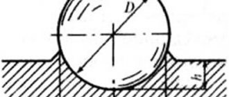
When determining hardness by this method, a steel ball of a certain diameter D is pressed into the test sample under the action of a load P applied perpendicular to the surface of the sample for a certain time. After removing the load, the diameter of the indentation d is measured. The Brinell hardness number is designated by the letters HB and is determined by dividing the load P by the surface area of the spherical imprint F.
For convenience, there are tables of Brinell hardness numbers and dependence on the ball diameter D, indent diameter d and load P.
Polished (Ra < 0.04 µm) balls made of ShKh15 steel with nominal diameters D = 1 are used as indenters; 2; 2.5; 5 and 10 mm, the latter are considered more preferable, as they provide greater accuracy in hardness measurement.
The minimum permissible sample thickness for correct measurement of NV hardness must be at least ten times the indentation depth h.
Tests are carried out at room temperature in the absence of vibrations and shocks. The holding time under load t for ferrous metals is 10...15 s, and for non-ferrous metals and alloys from 10 to 180 s. The load on the indenter is selected taking into account the ratio K=P/D2:
Metals and alloys K, kgf/mm2
Steel, cast iron and other high-strength alloys………..30
Copper, nickel and their alloys……………………………………..10
Aluminum, magnesium and their alloys……………………………………………………5
For example, when testing steels and cast irons with a ball diameter D = 10 mm, the load should be 3000 kgf, and the holding time under load should be 10...15 s. The hardness number in this case is indicated by numbers followed by the symbol HB (for example, 250 HB). Sometimes after the letters НВ test conditions are indicated - НВ D/P/τ, for example: 250 НВ 5/750/25 - Brinell hardness 250, obtained with a ball diameter D = 5 mm, load P = 750 kgf and holding time under load t =25 s. Brinell hardness testing is not recommended for steel with a hardness of more than 450 HB, and for non-ferrous metals with a hardness of more than 200 HB
Determination of metal hardnessHardness is the property of a material to resist elastic and plastic deformation or destruction when another, harder body that does not receive residual deformation - an indenter - is introduced into the surface layer of the material.
Methods for determining hardness, depending on the temporary nature of the application of load and measuring the resistance to indentation of the indenter, are divided into static, dynamic
and kinetic
. The most common are static methods, in which the load is applied to the indenter smoothly and gradually, and the holding time under load is regulated by standards for the corresponding methods.
With dynamic methods
To determine hardness, the indenter acts on the sample with a certain kinetic energy expended on elastic recoil and/or the formation of an indent; dynamic hardness is often also called the hardness of the material upon impact. Impact hardness characterizes the resistance to penetration not only on the surface of the sample, but also in a certain volume of the material.
Kinetic methods
Hardness determinations are based on continuous recording of the process of indentation of the indenter with recording of the diagram “load on the indenter - depth of penetration of the indenter. The peculiarity of this approach is to record the entire kinetics of the process of elastoplastic deformation of the material during indentation of the indenter, and not just the final test result, as with other methods.
According to the principle of applying the load, methods for determining hardness can be divided into methods of indentation, rebound, scratching
and cutting
.
Pressing methods
are the most common.
Hardness in this case is defined as the resistance that the test body provides to the penetration of a harder indenter and primarily reflects the resistance of the surface layers of the material to plastic deformation. Rebound
methods are based on measuring hardness by the height of the rebound of the striker falling onto the test surface. In this case, hardness primarily reflects resistance to elastic deformation. Rebound hardness testing is widely used to control the quality of mill rolls, large products and structures using portable instruments.
scratching
and cutting
methods , hardness is defined as the material's resistance to scratching or cutting, respectively. The scratching method was developed by Mohs at the beginning of the 19th century; they were given a scale of mineral hardness based on the ability of one to scratch the surface of another. This ten-point scale (from talc No. 1 to diamond No. 10) is used in mineralogy, as well as for assessing the hardness of technical ceramics and monocrystals.
When determining hardness by all methods (except microhardness), the integral value of the material’s hardness (averaged for all structural components) is measured. Therefore, the resulting imprint after removing the load should be significantly larger in size than the size of the grains and other structural components of the material being tested.
Hardness values cannot be unambiguously translated into values for other mechanical properties of the material (see below). However, determining hardness is an effective way to compare materials of the same type with each other and control their quality. Metal products made from copper and copper alloys as delivered are divided into five types based on hardness (see below).
Brinell hardness
In the practical determination of hardness by different methods, the load P is still usually specified in kgf.
The Brinell hardness measurement method is regulated by GOST 9012.
When determining hardness by this method, a steel ball of a certain diameter D is pressed into the test sample under the action of a load P applied perpendicular to the surface of the sample for a certain time (Fig. 1). After removing the load, the diameter of the indentation d is measured. The Brinell hardness number is designated by the letters HB and is determined by dividing the load P by the surface area of the spherical imprint F.
For convenience, there are tables of Brinell hardness numbers and dependence on the ball diameter D, indent diameter d and load P.
Rice. 1. Brinell hardness measurement scheme
D are used as indenters
= 1; 2; 2.5; 5 and 10 mm, the latter are considered more preferable as they provide greater accuracy in hardness measurement (especially when measuring the hardness of cast iron or coarse-grained alloys).
The minimum permissible sample thickness for correct measurement of NV hardness must be at least ten times the indentation depth h
.
Tests are carried out at room temperature in the absence of vibrations and shocks. The holding time under load t for ferrous metals is 10...15 s, and for non-ferrous metals and alloys from 10 to 180 s. The load on the indenter is selected taking into account the ratio K = P/D2:
Metals and alloys K, kgf/mm2
Steel, cast iron and other high-strength alloys………….30
Copper, nickel and their alloys………………………………….10
Aluminum, magnesium and their alloys………………………….. 5
For example, when testing steels and cast irons with a ball diameter D = 10 mm, the load should be 3000 kgf, and the holding time under load should be 10...15 s. The hardness number in this case is indicated by numbers followed by the symbol HB (for example, 250 HB). Sometimes after the letters НВ test conditions are indicated - НВ D/P/τ, for example: 250 НВ 5/750/25 - Brinell hardness 250, obtained with a ball diameter D = 5 mm, load P = 750 kgf and holding time under load t = 25 s.
Brinell hardness measurement is not recommended for steel with a hardness of more than 450 HB, and for non-ferrous metals with a hardness of more than 200 HB.
Vickers hardness
The Vickers hardness measurement method is regulated by GOST 2999. The method is used to determine the hardness of parts and metal products of small thickness, as well as thin surface layers with high hardness.
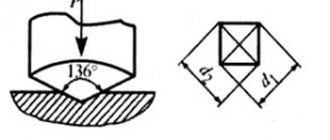
Vickers hardness is measured by pressing a diamond tip in the shape of a regular tetrahedral pyramid into the sample (product) under the influence of load P for a holding time τ (Fig. 2). After removing the roughness, measure the diagonals of the imprint remaining on the surface of the material – d1, d2 and calculate their arithmetic mean value – d, mm.
Vickers hardness values under standard loads depending on the diagonal length d (mm) are given in the corresponding tables.
During testing, the following loads P, kgf are used: 1; 2; 2.5; 3; 5; 10; 20; thirty; 50; 100.
The Vickers hardness number is denoted by numbers characterizing the hardness value followed by the symbol HV (for example, 200 HV). Sometimes the load and holding time are indicated after the HV symbol, for example: 200 HV 10/40 - Vickers hardness obtained at a load P = 10 kgf and holding time under load t = 40 s.
GOST says that there is no exact conversion of Vickers hardness numbers to hardness numbers obtained by other methods or to tensile mechanical properties and such conversions (except in special cases) should be avoided.
Figure 2. Vickers hardness measurement diagram
Rockwell hardness
The Rockwell hardness measurement method is regulated by GOST 9013. When determining hardness by this method (Fig. 3), the test sample (product) under the influence of two sequentially applied loads - preliminary P0 (usually P0 = 10 kgf) and total P - is pressed by an indenter (diamond cone or steel ball). In this case, the total load is equal to the sum of the preliminary P0 and main P1 loads:
P = P0+P1
After holding under the applied total load P for 3...5 s, the main load P1 is removed and the depth of penetration of the indenter into the material A is measured under the influence of the total load P, then the remaining preliminary load P0 is removed.
Rockwell hardness is measured in arbitrary units. The unit of hardness is taken to be the value corresponding to the axial movement of the indenter by 0.002 mm. The hardness number is determined using an indicator scale (usually a dial type). The indicator shows the result of subtracting the depth difference ( h –h0
), onto which the indenter is pressed under the action of two sequentially applied loads, from a certain constant.
The value h0
is the depth of penetration of the indenter into the test sample under the action of preload P0 (see Fig. 3).
Depending on the shape of the indenter and the applied load, three measuring scales have been introduced: A, B, C (Table 1). The most commonly used scales are A and C.
The Rockwell hardness number is indicated by numbers characterizing the hardness value followed by the symbol HIRA, HRB or HRC (depending on the measurement scale used), for example: 25.5 HRC
Rice.
3. Scheme for measuring Rockwell hardness scale
| Indicator used | Load, kgf | Application area | |||
| P - general | P0—preliminary | P1 - main | |||
| A | Diamond cone | 60 | 10 | 50 | Materials with hardness HRA 70 - 85 |
| B | steel ball | 100 | 10 | 90 | Low and medium carbon steels, brass, bronze and other materials with a hardness of HRB 25 - 100 |
| C | Diamond cone | 150 | 10 | 140 | Steels and alloys with hardness HRC 20 - 67 |
Tab. 1. Scales used to measure Rockwell hardness
Shore hardness
The Shore hardness measurement method is regulated by GOST 23273. This is the main method for determining the surface hardness of rolling rolls during their manufacture, delivery to a metallurgical enterprise, as well as during the operation of the rolls at rolling mills.
When measuring Shore hardness, a striker of a certain mass with a diamond indenter at the end falls freely vertically from a certain height hfall = 19.0 ± 0.5 mm onto the test surface of the material (Fig. 4). The indenter is a diamond tip in the form of a body of rotation with a radius of curvature of the working end R = 1.0 ± 0.1 mm. The mass of the striker together with the diamond indenter is 36.0 g.
The hardness characteristic is taken to be the rebound height of the striker h (see Fig. 4), measured in conventional units. A certain rebound value of the striker h100 = 13.6 ± 0.5 mm is taken as 100 Shore hardness units. This hardness corresponds to the maximum hardness of carbon eutectoid tool steel stabilized after martensite quenching according to GOST 1435. According to the standard, Shore hardness is measured in the range from 20 to 140 units (HSD).
The Shore hardness number is indicated by numbers characterizing the hardness value followed by the HSD symbol, for example 95 HSD. The hardness number is indicated rounded to the nearest whole number.
The Shore hardness value does not accurately translate to other hardness values or to strength properties obtained during mechanical testing.
Rice. 4 Shore hardness measurement scheme
Microhardness
The method for measuring microhardness is regulated by GOST 9450. Determination of microhardness (hardness in microscopically small volumes) is carried out when studying individual structural components of alloys, thin coatings, as well as when measuring the hardness of small parts. The device for determining microhardness consists of a mechanism for indenting a diamond pyramid under a small load and a metallographic microscope. A diamond pyramid is pressed into the test surface under a load of 0.05...5 N.
Microhardness is measured by pressing a diamond indenter into a sample (product) under the action of a static load P for a certain holding time t (see Fig. 5). The hardness number is determined (as in Vickers) by dividing the applied load in N or kgf by the nominal area of the lateral surface of the resulting indent in mm2.
The main test option is the so-called me
The method of the restored print, when the dimensions of the prints are determined after removing the load. In cases where it is necessary to determine additional characteristics of the material (elastic recovery, relaxation, creep at room temperature, etc.), it is allowed to test using the unrestored indentation method. In this case, the dimensions of the indentation are determined at the depth of indentation of the indenter during the application of the load.
In practice, microhardness is determined using standard tables of the specific indenter shape, load P and the dimensions of the indentation diagonals obtained in the test.
Diamond tips of different shapes and sizes are used as indenters, depending on the purpose of microhardness testing. The main and most common namnik tip is a tetrahedral diamond pyramid with a square base (the shape is similar to the indenter used in determining Vickers hardness - see Fig. 2).
The microhardness number is denoted by numbers characterizing the hardness value with the symbol H in front of them indicating the tip shape index, for example, H□ = 3000. It is allowed to indicate after the tip shape index the amount of applied load, for example: H□ 0.196 = 3000 - microhardness number 3000 N/mm2 , obtained by testing with a four-sided pyramid under a load of 0.196 N. The microhardness dimension (N/mm2 or kgf/mm2) is usually not indicated. If microhardness was determined using the unrestored print method, then the letter h (H□h) is added to the tip shape index.
Hardness value ratio
When comparing hardness values obtained by different methods with each other and with the mechanical properties of materials, it must be remembered that the tables or dependencies given in the literature for such a comparative translation are purely empirical. This translation has no physical meaning, since when pressing indenters of different shapes and sizes and with different loads, the hardness is determined under completely different stress states of the material.
Even with the same hardness measurement method, the value is highly dependent on the load: at lower loads, the hardness values are higher (Fig. 5).
Rice. 5. Dependence of Vickers hardness (HV) on test load
The same is true for comparing hardness values with the mechanical properties of the material, determined under tension or other forms of loading. In addition, the traditional mechanical characteristics of the material (proportional limit, yield strength, tensile strength, relative elongation, etc.) are integral characteristics of the entire test sample of the material and depend on the shape of the sample and test conditions. They, in particular, reflect the difference in the processes of structural self-organization in the internal and near-surface layers of the material, therefore they are strongly influenced by the state and structure of the surface layers of the material, including surface treatment, the presence of coatings, topographic structure of the surface, etc. For example , depending on the condition of the surface, the yield strength for the same material can differ by 50% or more. Hardness values, on the contrary, reflect the properties of the material under local loading by indentation of the indenter. Naturally, the integral properties of a material cannot, in principle, be completely derived from the local ones.
In connection with the above, one should use the translation of hardness numbers obtained by different methods very carefully and mainly for a preliminary assessment of the relative change in the properties of the material. However, in a number of specific cases and for the same or very similar materials in properties and structure, such a translation can be quite accurate and can serve as the basis for operational non-destructive testing methods. The approximate conversion of hardness values determined by various methods is given in table. 2.
| Brinell hardness (D= 10 mm, P= 3000 kgf), HB | Rockwell hardness (C scale, P = 150 kgf), HRC | Vickers hardness, HV | Shore hardness, HSD |
| 143 | — | 143 | 23 |
| 149 | — | 149 | 24 |
| 156 | — | 155 | 26 |
| 163 | 2 | 162 | 27 |
| 170 | 4 | 171 | 28 |
| 179 | 7 | 178 | 29 |
| 187 | 9 | 186 | 30 |
| 197 | 12 | 197 | 31 |
| 207 | 14 | 208 | 33 |
| 217 | 17 | 217 | 34 |
| 229 | 20 | 228 | 36 |
| 241 | 23 | 240 | 38 |
| 255 | 25 | 255 | 40 |
| 269 | 27 | 270 | 42 |
| 285 | 29 | 285 | 44 |
| 302 | 31 | 303 | 46 |
| 321 | 33 | 320 | 49 |
| 341 | 36 | 344 | 51 |
| 363 | 39 | 380 | 54 |
| 388 | 41 | 401 | 57 |
| 415 | 43 | 435 | 61 |
| 444 | 46 | 474 | 64 |
| 477 | 49 | 534 | 68 |
| 514 | 52 | 587 | 73 |
| 555 | 56 | 650 | 78 |
| 600 | 60 | 746 | 84 |
| 653 | 64 | 868 | 91 |
| 682 | 66 | 941 | 94 |
| 712 | 68 | 1022 | 98 |
| 745 | 70 | 1116 | 102 |
| 780 | 72 | 1220 | 106 |
Table 2. Approximate translation of hardness numbers determined by various methods (according to M.L. Bernstein, A.G. Rakhshtadt, etc.)
According to the hardness in the delivered state, rolled metal of heavy non-ferrous metals and alloys of domestic OCM plants are divided into the following types depending on the degree of cold deformation after annealing: soft (M) - ε = 0, quarter-hard (CH) - ε = 5... 10%, semi-hard ( PT) - ε = 15...25%, hard (T) - ε = 35...50%, extra hard (OT) - ε > 50
Since hardness is indirectly related to other indicators of mechanical properties, rolled products of a certain hardness have, but in many cases, strength, ductility or elasticity that is quite specific for a given state.
However, as was shown above, there is no explicit connection between hardness and other mechanical properties. Therefore, the finished rolled products are subjected to various mechanical tests (for example, tensile testing), technological tests are performed for extrusion of the hole, bending, etc.
Vickers hardness measurement
The Vickers hardness measurement method is regulated by GOST 2999. The method is used to determine the hardness of parts and metal products of small thickness, as well as thin surface layers with high hardness.
Vickers hardness is measured by pressing a diamond tip in the shape of a regular tetrahedral pyramid into the sample under the action of a load P for a holding time τ. After removing the load, measure the diagonals of the imprint remaining on the surface of the material – d1, d2 and calculate their arithmetic mean value – d, mm.
Vickers hardness values under standard loads depending on the diagonal length d (mm) are given in the corresponding tables.
During testing, the following loads P, kgf are used: 1; 2; 2.5; 3; 5; 10; 20; thirty; 50; 100. The Vickers hardness number is denoted by numbers characterizing the hardness value followed by the symbol HV (for example, 200 HV). Sometimes the load and holding time are indicated after the HV symbol, for example: 200 HV 10/40 - Vickers hardness obtained at a load P = 10 kgf and holding time under load t = 40 s.
GOST says that there is no exact conversion of Vickers hardness numbers to hardness numbers obtained by other methods or to tensile mechanical properties and such conversions (except in special cases) should be avoided.
What are the requirements for the product to be measured?
Hardness is directly proportional to the load to determine it. High hardness – high load.
The more accurate the method, the higher the requirements for preparing the surface of the product. The surface of the product on which hardness is determined must meet a number of requirements:
- The thickness of the sample must be at least 10 times the depth of penetration of the tip after removing the main force.
- At the inspection site, it must be cleaned to a shine, be smooth and flat, and must be free of scale, rust, oil, fat and paint contamination, potholes and scratches. Roughness Ra is not more than 2.5 µm according to GOST 2789, unless there are other requirements of regulatory and technical documentation.
- The surface on which the sample “lays” on the object stage of the device must also be clean and level. Both surfaces must be parallel to each other.
- The product must be securely fastened, excluding the possibility of displacement of the sample relative to the axis of load application.
Rockwell hardness test
The Rockwell hardness measurement method is regulated by GOST 9013. When determining hardness by this method, the test sample under the influence of two sequentially applied loads - preliminary P0 (usually P0 = 10 kgf) and total P - is pressed by an indenter (diamond cone or steel ball). In this case, the total load is equal to the sum of the preliminary P0 and main P1 loads:
P = P0+P1
After holding under the applied total load P for 3...5 s, the main load P1 is removed and the depth of penetration of the indenter into the material A is measured under the influence of the total load P, then the remaining preliminary load P0 is removed.
Rockwell hardness is measured in arbitrary units. The unit of hardness is taken to be the value corresponding to the axial movement of the indenter by 0.002 mm. The hardness number is determined using an indicator scale (usually a dial type). The indicator shows the result of subtracting the difference in depths (h – h0) to which the indenter is pressed under the action of two sequentially applied loads from a certain constant. The value h0 is the depth of penetration of the indenter into the test sample under the influence of preload P0.
Depending on the shape of the indenter and the applied load, three measuring scales are introduced: A, B, C. The most commonly used scales are A and C.
The Rockwell hardness number is indicated by numbers characterizing the hardness value followed by the symbol HRA, HRB or HRC (depending on the measurement scale used), for example: 28 HRC
Scales used to measure Rockwell hardness
Hardness of electroplated coatings
In the case of electroplated coatings, it should be noted that due to their small thickness, many methods (especially indentation methods) may not be suitable. The most common methods are Mohs and Vickers.
To measure hardness, a coating with a minimum thickness of 2 µm is required. If a smaller thickness is required, use GOST 9013-59, GOST 9012-59, GOST 22761-77
The measurement principle is the same. After applying the coating and drying it, the quality control department takes measurements and makes a decision - to ship the product or send it for recoating.
An important role here is played by both the electrolyte in which the coating is applied and the coating application mode (temperature, current density). For example, in one chrome plating electrolyte it is possible to obtain a chrome coating with a hardness from 500 to 1100 kgf/mm2.
If we talk about the electrolyte, the most important role is played by the quantity and quality of the brightening agents in it. A matte zinc coating will be much softer than a shiny one. Therefore, if you want a super-shiny coating, keep in mind that it will be hard, and there is a possibility of it cracking or peeling off at the slightest bending of the product.
Shore hardness measurement
The Shore hardness measurement method is regulated by GOST 23273. This is the main method for determining the surface hardness of rolling rolls during their manufacture, delivery to a metallurgical enterprise, as well as during the operation of the rolls at rolling mills.
When measuring Shore hardness, a striker of a certain mass with a diamond indenter at the end freely pushes vertically from a certain height h of fall = 19.0 ± 0.5 mm onto the test surface. The indenter is a diamond tip in the form of a body of rotation with a radius of curvature of the working end R = 1.0 ± 0.1 mm. The mass of the striker together with the diamond indenter is 36.0 g. The rebound height of the striker h is taken as the hardness characteristic. A certain rebound value of the striker h100 = 13.6 ± 0.5 mm is taken as 100 Shore hardness units. This hardness corresponds to the maximum hardness of carbon eutectoid tool steel stabilized after martensite quenching according to GOST 1435. According to the standard, Shore hardness is measured in the range from 20 to 140 units (HSD). The Shore hardness number is indicated by numbers characterizing the hardness value followed by the HSD symbol, for example 95 HSD. The hardness number is indicated rounded to the nearest whole number.
Microhardness measurement
The method for measuring microhardness is regulated by GOST 9450. Determination of microhardness (hardness in microscopically small volumes) is carried out when studying individual structural components of alloys, thin coatings, as well as when measuring the hardness of small parts. The device for determining microhardness consists of a mechanism for indenting a diamond pyramid under a small load and a metallographic microscope. A diamond pyramid is pressed into the test surface under a load of 0.05...5 N.
Microhardness is measured by pressing a diamond indenter into a sample (product) under the influence of a static load P for a certain holding time t. The hardness number is determined (as in Vickers) by dividing the applied load in N or kgf by the conditional area of the lateral surface of the resulting indent in mm2.
The main test option is the so-called reconstructed indentation method, when the dimensions of the indentations are determined after removing the load. In cases where it is necessary to determine additional characteristics of the material (elastic recovery, relaxation, creep at room temperature, etc.), it is allowed to test using the unrestored indentation method. In this case, the dimensions of the indentation are determined at the depth of indentation of the indenter during the application of the load.
In practice, microhardness is determined using standard tables of the specific indenter shape, load P and the dimensions of the indentation diagonals obtained in the test.
Diamond tips of different shapes and sizes are used as indenters, depending on the purpose of microhardness testing. The main and most common tip is a tetrahedral diamond pyramid with a square base (similar in shape to the indenter used in determining Vickers hardness).
The microhardness number is indicated by numbers characterizing the hardness value with the symbol H in front of them indicating the tip shape index, for example, H□ =3000. It is allowed to indicate after the tip shape index the magnitude of the applied load, for example: Н□ 0.196 =3000 - microhardness number 3000 N/mm2, obtained by testing with a four-sided pyramid under a load of 0.196 N. The microhardness dimension (N/mm2 or kgf/mm2) is usually not indicate. If microhardness was determined using the unrestored print method, then the letter h (H□h) is added to the tip shape index.
Hardness value ratio
When comparing hardness values obtained by different methods with each other and with the mechanical properties of materials, it must be remembered that the tables or dependencies given in the literature for such a comparative translation are purely empirical. This translation has no physical meaning, since when pressing indenters of different shapes and sizes and with different loads, the hardness is determined under completely different stress states of the material. Even with the same hardness measurement method, the value is highly dependent on the load: at lower loads, the hardness values are higher.
The main methods of hardness control were discussed above.
There are other control methods that are based on indirect measurements of mechanical properties. For example electrical, magnetic, acoustic, etc. All these methods are based on the compilation of experimental correlation tables “measured parameter - parameter of mechanical properties”, where all parameters are constant (chemical composition of the metal, heat number, amount of contaminants), and only the tabulated parameters change. Such methods practically do not work in production, because... for example, the chemical composition of metals according to GOST standards is required in the selection, i.e. can be within a given limit and vary from heat to heat. Compiling calibration tables for each batch of metal is a very labor-intensive job. Pla plastic solvent - https://www.dcpt.ru
The essence of methods for determining the hardness of metals
Tests can be carried out both on reference samples (made from the same metal and subjected to the same heat treatment) and directly on finished parts. In the latter case, it is necessary to take measures to ensure that the tested product does not subsequently suffer external damage.
The choice of hardness testing method depends on:
- Initial mechanical indicators of strength, elasticity and ductility of the product.
- Overall dimensions of the part (or the junction of adjacent structural elements, if hardness is established in the area, for example, of a weld).
- Final result: establish the hardness of the product itself, or the hardness of only its surface (performed for parts that have undergone heat treatment or another type of surface hardening).
- Requirements for the conditions, time and place of testing. For example, in field conditions, portable hardness testers are more suitable than stationary ones.
- Stability of measurement results and their reproducibility during repeated testing.
Hardness can be measured by three groups of methods - mechanical (static and dynamic), as well as ultrasonic. In addition, a distinction is made between hardness at room and elevated temperatures (the so-called “hot hardness”). Regardless of this, the physical essence of all methods is the same - a deforming element is introduced into the sample, the movement of which is read on a special scale.
Hardness is considered as the resistance of a metal to irreversible plastic deformation, and therefore differs from other measurements by the presence of special unified instruments - hardness testers for metals.
How to determine the chemical composition of a metal, read the link