Thyristor
A thyristor is a switching semiconductor device that passes current in one direction.
This radio element is often compared to a controlled diode and is called a semiconductor controlled rectifier (SCR). The thyristor has three outputs, one of which - the control electrode, one might say, the “trigger” - is used to abruptly switch the thyristor to the on state.
The thyristor combines the functions of a rectifier, switch and amplifier. It is often used as a regulator, mainly when the circuit is powered by alternating voltage. The following points reveal the four main properties of a thyristor:
- A thyristor, like a diode, conducts in one direction, acting as a rectifier;
- The thyristor is switched from the off state to the on state when a signal is applied to the control electrode and, therefore, like a switch, has two stable states. However, to return the thyristor to the off (open) state, special conditions must be met;
- the control current required to transfer the thyristor from a closed state to an open state is significantly less (several milliamps) with an operating current of several amperes and even several tens of amperes. Consequently, the thyristor has the properties of a current amplifier;
- oThe average current through a load connected in series with a thyristor can be precisely adjusted depending on the duration of the signal at the control electrode. The thyristor is a power regulator.
Why is verification needed?
In the process of repairing or assembling a new circuit, it is impossible to do without electrical parts. One of these parts is a triac. It is used in alarm circuits, light controllers, radio devices and many branches of technology. Sometimes it is reused after dismantling non-working circuits, and it is not uncommon to encounter an element whose markings have been lost due to long-term use or storage. It happens that new parts need to be checked.
How can you be sure that the triac installed in the circuit is really working, and in the future you will not need to spend a lot of time debugging the operation of the assembled system?
To do this, you need to know how to test a triac with a multimeter or tester. But first you need to understand what this part is and how it works in electrical circuits.
In fact, a triac is a type of thyristor. The name is made up of these two words - “symmetrical” and “thyristor”.
Thyristor structure
A thyristor is a controlled three-electrode semiconductor device consisting of alternating four silicon layers of type p and n. A semiconductor device with a four-layer structure is shown in Fig. 1.
The extreme region of the p-structure, to which the positive pole of the power source is connected, is usually called the anode, and the extreme region n, to which the negative pole of this source is connected, is called the cathode.
Fig.1. Thyristor structure and designation
Properties of the thyristor in the closed state
According to the structure of the thyristor, three electron-hole junctions can be identified and the thyristor can be replaced with an equivalent circuit, as shown in Fig. 2.
This equivalent circuit allows us to understand the behavior of the thyristor with the control electrode disconnected.
If the anode is positive with respect to the cathode, then diode D2 is closed, which leads to the closure of the thyristor, which in this case is forward biased. With a different polarity, diodes D1 and D2 are reverse biased, and the thyristor is also turned off.
Fig.2. Representation of a thyristor by three diodes
Equivalent to low voltage gas arrester
In Fig. Figure 7 shows a diagram of a device equivalent to a low-voltage gas discharger [PTE 4/83-127]. This device is a gas-filled cylinder with two electrodes, in which an electrical interelectrode breakdown occurs when a certain critical voltage value is exceeded.
The “breakdown” voltage for an analogue of a gas spark gap (Fig. 7) is 20 V. In the same way, an analogue of, for example, a neon lamp can be created.
Rice. 7. Analogue of a gas discharger - equivalent replacement circuit.
Opening principle using a control electrode
An equivalent representation of the p-npn structure in the form of two transistors is shown in Fig. 3.
Representing a thyristor in the form of two transistors of different conductivity types leads to the equivalent circuit shown in Fig. 1.4. It clearly explains the phenomenon of thyristor unlocking.
Let us set the current IGT through the control electrode of the thyristor, biased in the forward direction (voltage VAK positive), as shown in Fig. 4.
Since the IGT current becomes the base current of the npn transistor, the collector current of this transistor is equal to B1xIGT, where B1 is the current gain of transistor T1.
This current is also the base current of the pnp transistor, which leads to its unlocking. The collector current of transistor T2 is B1xB2xIGT and is summed with the current IGT, which maintains transistor T1 in the open state. Therefore, if the IGT drive current is large enough, both transistors will go into saturation.
The internal feedback circuit maintains the conductivity of the thyristor even if the initial current of the IGT control electrode disappears, while the anode current (1A) remains quite high.
A typical thyristor startup circuit is shown in Fig. 5
.
Fig.3. Splitting a thyristor into two transistors
Fig.4. Representation of a thyristor as a two-transistor circuit
Fig.5. Typical thyristor trigger circuit
Thyristor shutdown
The thyristor will go into the closed state if no signal is applied to the control electrode of the open thyristor, and its operating current drops to a certain value called the holding current (hypostatic current).
The thyristor will turn off, in particular, if the load circuit was open (Fig. 6a) or the voltage applied to the external circuit changed polarity (this happens at the end of each half-cycle of the alternating supply voltage).
Fig.6. Methods for turning off a thyristor
When the thyristor operates at constant current, switching off can be done using a mechanical switch.
Connected in series with the load, this switch is used to disconnect the operating circuit.
A switch connected in parallel to the main electrodes of the thyristor (Fig. 6b) shunts the anode current, and the thyristor goes into the closed state. Some thyristors turn on again after the switch is opened. This is explained by the fact that when the switch is opened, the parasitic capacitance of the p-n junction of the thyristor is charged, causing interference.
Therefore, they prefer to place the switch between the control electrode and the cathode of the thyristor (Fig. 1.6c), which guarantees correct shutdown by cutting off the holding current. At the same time, the p-n junction corresponding to diode D2 from the thyristor equivalent circuit with three diodes is reverse-biased (Fig. 2).
In Fig. 6a-e show various options for thyristor shutdown circuits, including those previously mentioned. Others are usually used when it is necessary to turn off the thyristor using an additional circuit. In these cases, the mechanical switch can be replaced by an auxiliary thyristor or a key transistor, as shown in Fig. 7.
Fig.7. Classic thyristor shutdown circuits using an additional circuit
How to avoid false positives
Since a small potential is enough to trigger a triac, false alarms are possible. In some cases, they are not terrible, but they can also lead to damage. Therefore, it is better to take action in advance. There are several ways to reduce the likelihood of false inclusions:
- Reduce the length of the line to the gate, connect the control circuit - gate and T1 - directly. If this is not possible, use shielded cable or twisted pair.
- Reduce shutter sensitivity. To do this, place a resistance in parallel (up to 1 kOhm).
In almost all circuits with triacs, there is a resistor in the gate circuit that reduces the sensitivity of the device
- Use triacs with high noise immunity. They have the letter “N” added to their labeling, for “insensitive”. They are called “H-series triacs”. They differ in that the minimum transition current is much higher. For example, a BT139-600H triac has a transition current IGT min =10mA.
As already said, the triac is controlled by current. This makes it possible to connect it directly to the outputs of the microcircuits. There is one limitation - the current should not exceed the maximum permissible. Typically this is 25 mA.
Triac
SIMCMOP is a semiconductor device that is widely used in systems powered by alternating voltage. In simple terms, it can be considered as a controlled switch. When closed, it behaves like an open switch. On the contrary, the supply of control current to the control electrode of the triac leads to its transition to a conducting state. At this time, the triac is like a closed switch.
In the absence of control current, the triac inevitably passes from the conduction state to the closed state during any half-cycle of the alternating supply voltage.
In addition to operating in relay mode in a thermostat or photosensitive switch, control systems have been developed and are widely used that operate on the principle of phase control of the load voltage, or, in other words, smooth regulators.
Triac unlocking
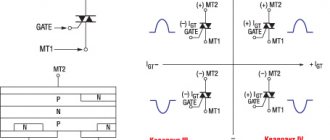
In alternating power mode, a change in the states of the triac is caused by a change in the polarity of the voltage on the working electrodes A1 and A2. Therefore, depending on the polarity of the control current, four options for controlling the triac can be defined, as shown in Fig. 9.
Each quadrant corresponds to one way of opening the triac. All methods are briefly described in table. 1.
Fig.9. Four possible triac control options
Table 1. Simplified representation of methods for opening a triac
| Quadrant | VA2-A1 | VG-A1 | I.G.T. | Designation |
| I | >0 | >0 | Weak | + + |
| II | >0 | Average | + — | |
| III | Average | — — | ||
| IV | >0 | High | — + |
For example, if a voltage VA1-A2>0 is applied between the working electrodes of a triac and the voltage on the control electrode is negative with respect to the anode A1, then the bias of the triac corresponds to quadrant II and the simplified designation + -.
For each quadrant, the unlocking current I from (IGT), the holding current Iud (In) and the switching current Ioff (IL) are determined.
The unlocking current must be maintained until the operating current exceeds two to three times the holding current In. This minimum unlocking current is the turn-on current of the triac IL.
Then, if the current through the control electrode is removed, the triac will remain in a conducting state as long as the anode current exceeds the holding current In.
Where is it used and what does it look like?
Most often, a triac is used for switching in alternating current circuits (supplying power to the load). This is convenient, since using a low nominal voltage you can control high-voltage power. In some circuits, a triac is installed instead of a conventional electromechanical relay. The advantage is obvious - there is no physical contact, which makes turning on the power more reliable. The second advantage is the relatively low price. And this is with a significant operating time and high reliability of the circuit.
There are also disadvantages. Devices can become very hot under load, so it is necessary to ensure heat dissipation. Powerful triacs (usually called “power”) are mounted on radiators. Another disadvantage is that the voltage at the output of the triac is sawtooth. That is, only loads that do not place high demands on the quality of the power supply can be connected. If you need a sinusoid, this switching method is not suitable.
You can replace a triac with two thyristors. But you need to select them correctly according to the parameters, and the control circuit will have to be redone - in this version there are two control outputs
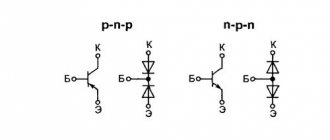
It is impossible to distinguish a thyristor and a triac by appearance. Even the markings may be similar - with the letter “K”. But there are also series whose names begin with “TS,” which means “symmetrical thyristor.” If we talk about pinout, this is what distinguishes a thyristor from a triac. A thyristor has an anode, a cathode and a control terminal. For a triac, the names “anode” and “cathode” are not applicable, since the output can be both a cathode and an anode. So they are usually called simply "power terminal" and have a number added to it. The one to the left is the first, the one to the right is the second. The control electrode can be called a gate (from the English word Gate, which refers to this output).