1 – foot; 2 – tail; 3 – neck; 4 – groove
Rice. 1.18. Drill clamping accessories:
a – three-jaw chuck; b – adapter conical bushing
A drill with a cylindrical shank is pre-fixed in a special chuck (Fig. 1.18, a). In the case when the drill cone is smaller than the cone in the machine spindle, tapered adapter bushings are used (Fig. 1.18, b). The foot - the end part of the drill - serves as a stop when knocking the drill out of the machine spindle. When drilling, the workpiece is fixed motionless, and two joint movements are communicated from above (Fig. 1.17): rotational (along the arrow I) and translational, directed along the axis of the drill (along the arrow II). The rotational movement of the drill is called the main movement, and the translational movement is called the feed movement.
Drilling is used when it is necessary to obtain holes of a low degree of accuracy and a low roughness class, for example, for fastening bolts and studs, as well as for threading, reaming and countersinking. If the hole in the part is not through, then the operation is called drilling, and increasing the diameter of the hole is called reaming, or countersinking.
During the drilling process, the cutting edges of the drill grind down and it becomes inoperable. To restore the cutting properties of the drill, it is sharpened. The angle at the tip of the drill obtained as a result of sharpening is checked with special templates (Fig. 1.19). The value of this angle is selected depending on the material being processed (Table 1.1).
Rice. 1.19. Checking the drill when sharpening according to the template:
a – template; b – measuring the length of the cutting edge;
c – measurement of the angle at the apex; d – measurement of the sharpening angle;
d – measurement of the angle of inclination of the transverse edge
Table 1.1 Dependence of the apex angle on the material being processed
To reduce friction, the drill has a reverse taper: its diameter decreases towards the shank by 0.03...0.12 mm for every 100 mm of length.
Drills are made from steel grades R9, R18, R9K10, R6M5, R18K5F2, U12A, and are equipped with plates made of hard alloys and composite materials.
When drilling holes, the diameter of the drill is selected depending on the diameter of the fastener - bolt or stud (Table 1.2).
Table 1.2 Drill diameter when obtaining a hole for a fastener
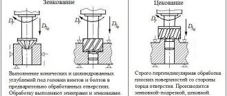
Countersinking
- this is the operation of processing cylindrical or conical recesses and chamfers of drilled holes for the heads of bolts, screws and rivets (Figure 1.20, a).
The cutting tool is a countersink. According to the shape of the cutting part, countersinks are divided into cylindrical, conical and end-face (counterbore). All of them consist of a working part and a shank. Rice.
1.20. Methods for processing holes: a – countersinking; b – countersinking; c – deployment
The working part of the cylindrical countersink has from 4 to 8 end teeth and a guide pin, which fits into the drilled hole, which ensures that the axis of the hole coincides with the cylindrical recess formed by the countersink.
On a conical countersink, the working part has a cone at the apex. The most common are conical countersinks with a cone angle of 30, 60, 90 and 120*.
Countering is carried out with face countersinks for cleaning the end surfaces, processing bosses for washers, thrust rings, and nuts. For the manufacture of countersinks, steel grades P9 and P18 are used.
Countersinking
– the process of processing cylindrical and conical raw holes in order to increase the diameter, improve the quality of their surface, increase accuracy (reduce taper, ovality, breakdown). Countersinking is performed on drilling machines with countersinks (Fig. 1.20, b), which in appearance resemble a drill and consist of the same basic elements, but have a larger number of cutting edges (3–4) and spiral grooves.
Countersinks are made from steel grades P9, P18, 9HS, U12A of two types: solid with a diameter of 10...40 mm with a working part length of 80...200 mm and mounted with a diameter of 32...80 mm with a length of 10...18 mm.
Holes that need to be machined with a countersink after drilling should have a smaller diameter compared to the diameter of the final machined hole (Table 1.3).
Table 1.3 Countersink diameter taking into account allowance
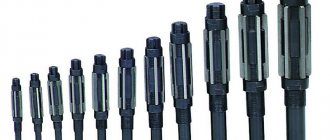
Deployment
– processing of holes after drilling, countersinking or boring to give them the required high accuracy and roughness (Fig. 1.20, c).
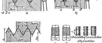
The main tool is a reamer, which consists of a working part, a neck and a shank. Depending on the shape of the hole being machined, cylindrical and conical reamers with 6…12 teeth are used. Based on their design, reamers are divided into solid, adjustable, and with inserted teeth, and based on the method of use, they are divided into manual and machine.
When reaming holes manually, a reamer with an uneven distribution of teeth around the circumference is used, which helps to obtain a less rough surface. Machine reamers have an even number of evenly distributed teeth. The more teeth, the less rough the processed surface is.
Cylindrical and conical reamers are made from steel grades P9, 9ХС as a complete set. In a set of three scans, the first is rough, the second is transitional, and the third is finishing.
The thickness of the metal layer removed by a reamer depends on the diameter of the hole (Table 1.4).
Table 1.4 Allowance for diameter when reaming
Countersinking
With the help of countersinking, performed using a special cutting tool, the following tasks related to the processing of holes produced by casting, stamping, forging or through other technological operations are solved:
- bringing the shape and geometric parameters of the existing hole into accordance with the required values;
- increasing the accuracy of the parameters of a pre-drilled hole up to the eighth grade;
- processing of cylindrical holes to reduce the degree of roughness of their internal surface, which, when using such a technological operation, can reach a value of Ra 1.25.
When countersinking, less cutting force is applied than when drilling, and the hole is more accurate in shape and size
If it is necessary to subject a hole of small diameter to such processing, it can be performed on tabletop drilling machines. Countersinking of large diameter holes, as well as processing of deep holes, is carried out using stationary equipment installed on a special foundation.
Deployment
The reaming procedure involves holes that were previously drilled into the part. An element processed using such a technological operation can have accuracy up to the sixth grade, as well as low roughness - up to Ra 0.63. Reamers are divided into rough and finishing, and they can also be manual or machine.
Cylindrical manual reamers 24Н8 0150
The recommendations that should be followed when performing this type of processing are as follows.
- Allowances in the diameter of the hole being machined are selected according to special tables.
- When using a hand tool that is rotated only clockwise, first perform rough reaming and then finish reaming.
- Steel parts are processed with the obligatory use of coolant, while cast iron parts are processed dry.
- Machine reaming is carried out immediately after drilling on the machine - with one installation of the part.
- To control the quality of the result, special calibers are used.
Drilling on lathes
A lathe is a universal machine for various types of work with rotating workpieces. Therefore, it can also be used to perform various hole processing: drilling, reaming, reaming, countersinking, countersinking, etc. To simplify work on lathes, special equipment is used - CNC (computer numerical control). Installation of CNC equipment is possible on various types of lathes. Screw-cutting lathes, carousel, revolving and other types are suitable for this purpose. You can also drill holes using CNC equipment.
Countersinking is an increase in the diameter of a hole using a countersink, and countersinking is the processing of its edge using a countersink.
Types of drilling on lathes
Conventionally, there are three types of process of drilling holes on a lathe according to the degree of human intervention:
- Manual. This method involves feeding the cutting tool into the cutting zone using a tailstock flywheel driven by human muscle power.
- Mechanical. With this method of processing holes, the drill is fed using a mechanical feed coming from the caliper carriage to the tailstock through a special device. Not all lathes have such devices and, accordingly, the ability to carry out mechanical drilling.
- Using CNC. Full automation of product processing is possible on CNC machines. On a CNC lathe, you can make holes using various methods and tools without human intervention.
The process of drilling and reaming holes on lathes
To create new holes in a workpiece or change the size of old ones, the following types of operations must be performed on a lathe:
- Align the tailstock so that the quill axis coincides with the spindle axis.
- Secure the workpiece in the headstock chuck so that it protrudes beyond the level of the jaws as little as possible.
- Install the cutting tool in the tailstock quill. If you have to change it frequently, it is better to use a quick-change chuck and a set of special bushings. This will help to significantly reduce the time required to change tools. When using a quick-change chuck, all drills, countersinks, reamers, etc. must have shanks with the same Morse taper number. At the beginning of drilling, the quill should be pulled out from the tailstock to the shortest possible distance.
- The first work operation is preparing the end of the workpiece. It should be smooth. This is done by trimming the end with a cutter.
- Make a small recess at the end of the part. This operation will help you drill exactly at the rotation point of the workpiece. This recess is made with a persistent cutter or a short drill.
- Drill using the tailstock flywheel. Feed the tool smoothly. Periodically move it out of the cutting zone to free it from chips. Cool the cutting zone using a special emulsion.
- When through-cutting, you need to reduce the feed speed at the exit from the workpiece so as not to damage it when the load on the cutting edges increases sharply.
- To increase the diameter of the holes, you need to: install a drill of a larger diameter and drill; apply a countersink - carry out countersinking; use a boring cutter to make boring.
- To reduce roughness, reaming is used (the process is reaming).
- To work with edges, use a countersink (the process is countersinking).
Basics of turning
1. Cutting pattern and cutting conditions
During turning, as in all cases of cutting, there is a relative movement of the workpiece and the tool. In the relative movement of the workpiece and the tool, a distinction is made between the main movement, which ensures chip formation, and the auxiliary movement (feed movement), which makes the chip formation process continuous.
When turning, the main movement is the rotational movement of the workpiece, and the auxiliary movement - feed - ensures the movement of the cutter along the machined surface. Feed can be carried out in a straight line parallel to the axis of rotation of the workpiece - longitudinal feed, perpendicular to the axis of rotation - transverse feed, oblique feed is also used (when processing conical surfaces) and feed along a curved path (when processing shaped surfaces).