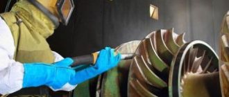
Sandblasting of metals is a technology for highly effective cleaning of various surfaces using an abrasive material. It is used as preparatory work before anti-corrosion or paint and varnish treatment of the surface. This method allows you to remove paint, rust, and also degrease the workpiece. Widely used in various industries: metallurgy, automotive industry, metal structures, instrument making.
Types of sandblasting
There are several types of metal cleaning:
- Easy. This type of sandblasting involves surface cleaning: it removes traces of old paint and large pockets of corrosion. The effectiveness of the effect is comparable to treatment with a metal brush. Upon visual inspection there should be no obvious signs of corrosion or contamination.
- Average. More thorough sandblasting. After processing the metal, minor traces of rust remain - no more than 10% of the total surface area.
- Deep. Completely removes traces of any contaminants. The metal surface should look absolutely clean. This type requires significant consumption of abrasive substances.
There is also an international standard for the degree of surface preparation. Evaluation is carried out by visual inspection. There are four degrees:
- Sa 1. Light sandblasting of metal.
- Sa 1–2. Sandblasting without mirror effect of metal.
- Sa 2–2.5. Sandblasting until the metal is almost shiny.
- Sa 3. Complete sandblasting until the metal shines.
Additional Information. Most manufacturers of paint and varnish products require preliminary surface preparation. Sandblasting metal allows you to not only clean, but also degrease the painted area. Thanks to this, the technology in question is considered the most effective.
Correct selection of sand
Before making the final choice, of course, in each individual case it is worth knowing exactly what kind of work sandblasting should do. For complex stains, when a strong abrasive effect is required, it is worth using quartz sand. If you need minimal treatment of a surface that is easily damaged, or simple contamination, then river sand is quite suitable for sandblasting. Before making a decision, it is best to check the table, which indicates the nuances of working with sand and the characteristics suitable for each type of work.
| Sand fraction | Type of work |
| Sand without fraction | Ordinary household work, those that do not require large amounts of material. This can be cleaning metal surfaces, wood, house facades. The contaminants that this sand can deal with are traces of corrosion, paint or a coating of small contaminants that must be removed before repainting. |
| 0.1-0.2 mm | Matting or applying patterns to glass or mirror |
| 0.3-0.6 mm | Removing a fresh layer of varnish or paint from different surfaces |
| Up to 0.3 mm | Polishing soft metals |
| 0.6-1.6 mm | Cleaning deep traces of stubborn rust |
| 2-5 mm | Welding scale removal |
The essence and purpose of the technology
The operating principle of the technology is based on the interaction of the abrasive with the metal surface.
A compressor is used as a working mechanism, which creates the necessary pressure in the working system. Sand or other material used is captured by the air flow and thrown onto the work surface. The average operating pressure of the system is 8 atmospheres, and therefore the speed of particles supplied by pressure can reach 700–720 m/s. This indicator ensures thorough cleaning, and therefore experts consider sandblasting to be the best preparation for painting metal. By exposing the surface to abrasive particles, two goals are achieved:
- clean metal from contamination;
- give roughness.
The use of various materials allows you to focus on one or another action. The roughness of the plane increases the adhesive properties of paints and varnishes, which ultimately affects the service life of the coating.
Please note that maximum durability can only be achieved by deep sandblasting the metal surface. If you do not get rid of traces of corrosion, the lesion will develop even under a layer of paint.
Industrial enterprises use sandblasting of metal structures to remove rust and dirt. The cleaned metal surface allows for high-quality welding work.
Pros and cons of sandblasting
Compared to other processing methods, experts highlight a number of advantages:
- Performance. Sandblasting an area is much faster.
- Quality. The high speed of the abrasive ensures the removal of any contaminants from the metal. The adjustment range allows you to achieve the desired degree of cleaning. The impact on the metal does not reduce its properties and does not affect the thickness.
- Practicality. Models differ in different operating parameters and dimensions: from compact devices for a private garage to sandblasting units for industrial use.
- Versatility. Components and consumables for any type of work are available for sale.
VIEW Portable Sandblasting Machine on AliExpress →
With all the positive aspects, there are some disadvantages:
- Operator training. It is necessary to complete a special training course in order to master all the skills of high-quality and safe sandblasting work.
- Price. The use of sandblasting metal in industrial production requires significant financial investments. In addition, to carry out the work it is necessary to select a separate room and find qualified workers.
- Operation at home. The use of sand as an abrasive material is associated with certain difficulties: after completion of work, sand particles remain in the air, increasing the dust level. Without personal protective equipment, respiratory tract damage can occur.
Occupational Safety and Health
The sandblasting installation is high-risk equipment.
- Persons who have reached the age of 18, have passed a medical examination and are fit for health reasons to perform this work are allowed to work on this type of equipment.
- Before work, you need to put on a work suit made of cotton fabric that protects against industrial pollution, protective leather work boots, and you need to put on safety glasses to protect your eyesight.
3. Therefore, before performing sandblasting work, the worker must be familiar with safe work practices.
- keep your workplace clean, do not block aisles and passages with products.
- Do not eat in the workplace; wash your hands with soap and water before eating.
Foundry technologist offers cooperation: * I offer all legal entities and individuals interested in obtaining high-quality castings consultations on solving problems in foundry production. Consultations on foundry technology: * reducing losses from defects, reducing gas and clogged sinks * increasing labor productivity by 5- 15%, without investing costs, by identifying losses and changing the chain of technological flows for manufacturing castings * selection of equipment for foundry * assistance in finding manufacturers of pattern equipment for foundry - negotiated individually. *Assistance in assessing the condition of foundry equipment. *Assistance in preparing production when mastering castings. *Advertising of casting manufacturers, foundry equipment, materials and devices for foundry production on this website. Contacts: tel:89080593100 Evgeniy e-mail
Main processing rules
High-quality cleaning of the treated surface is possible only if you select the equipment, components and consumables suitable for specific work correctly. Experience shows that to achieve a positive result, the following rules must be followed:
- The performance and pressure of the compressor should be sufficient for the selected sandblasting machine, and ideally have a power reserve of 20–30%.
- It is necessary to use large diameter air supply hoses - this will reduce pressure losses.
- Hose connectors and couplings must have the diameter of the supply hose.
- For large volumes of work, take care of the mobility of the unit.
- Use modern technological developments: remote control, moisture separator, high-strength boron carbide nozzles. The initial investment will pay off quickly.
- Do not skimp on personal protective equipment - this is the key to the sandblaster’s health.
Correctly selected equipment is half the battle. Don’t forget about training and advanced training of equipment operators.
Types of abrasives used
The first models of devices worked exclusively on sand.
This didn't last long. The technology of work involves the use of various materials for cleaning metal. Abrasive materials can be classified according to physical characteristics or origin. The first classification option is as follows:
- Hardness. The speed and intensity of metal processing depends on it.
- Fraction size. According to the laws of physics, large particles have greater impact force.
Important information! For uniform processing of metal, grain size is important. The use of a mixture containing fractions of different sizes leads to excessive consumption of abrasive.
- Form. The cleaning method depends on it. Round abrasive is effective in direct interaction with metal, and elongated fractions act by friction force. There is grain-shaped material. It has a polishing effect.
Based on their origin, abrasives are divided into the following groups:
- Natural. This includes special sand for sandblasting. During the development of technology, natural material was in great demand due to the lack of analogues. Desert and sea sands were especially valued. Modern safety requirements limit their use.
- Vegetable. Agricultural by-products. The seeds, husks or shells are processed and then used in production. The main quality of the material is its soft impact on the working area.
- Industrial. They are divided into three subcategories: metallic, non-metallic, waste from the metallurgical industry. The most famous abrasive of the first group is metal shot. Granulates and shot are made from almost all types of metal. They differ only in the size of the fraction. They are durable. Non-metallic abrasive is an industrial product. Features uniform grain size. It has high strength and excellent cleaning properties. A striking example is glass grain. The material from the last subcategory is obtained from waste slag. Has average characteristics. The main advantage is that industrial regions are able to supply this abrasive in large quantities.
Types of sandblasting equipment
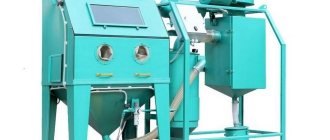
Manufacturers offer two types of equipment for sandblasting metal:
- Mobile device. Compact dimensions allow the unit to be moved by one person. The scope of work is limited only by supplies of consumables. Safety equipment is required for operation. Within the operating range of the device, dusty air can pose a danger to people.
- Automatic sandblasting chamber. It is safe for the installation operator. The enclosed space allows you to collect abrasive after work. Requires a high-quality ventilation system. The dimensions of the processed parts are limited.
Review of sandblasting machines and cost
There are three types of mobile sandblasting machines, which differ both in operating principle and in price. Let's look at each type.
VIEW Sandblasting equipment on AliExpress →
Pressure type device
Its peculiarity is the method of supplying abrasive, which enters the metal surface through one channel with compressed air. It has good performance, but is dependent on the power of the compressor unit. Suitable for cleaning large surfaces. Widely used in industrial enterprises for repairing metal structures. The minimum cost of such units is $300. An installation with average performance costs about $1000.
Additional Information! On the Internet you can find a diagram of the design of pressure devices. An experienced welder can assemble the installation within a week.
Injection type device
Abrasive and air enter through separate channels. Because of this, the nozzle holder has an air and abrasive nozzle. It has low performance. This determines the scope of application of the devices - decorative processing of mirrors and other surfaces. The cost does not exceed $300.
Vacuum devices
They were developed as a type of pressure apparatus, but their design features separated them into a separate class. After contact with the metal, the abrasive is sucked into the device by vacuum. However, it reduces the kinetic energy of the particles, which affects power. Low productivity and high cost have led to the fact that such units are used very rarely.
Waterjet cutting
3.1 Technological basis of waterjet cutting
According to the International Association of Industrial Engineers, in world practice, small-scale production, single and medium-scale production account for 70-80% of the total output of products in mechanical engineering.
The complexity of engineering products has increased on average sixfold over the past three decades. Of the total number of standard sizes of production parts, the largest share (more than 2/3 of the total product range) falls on flat parts of complex configuration. Flat parts with complex contours are widespread (more than 50% of the product range), and their processing accounts for 20-30% of the total cost of machining. With a monthly program of tens and hundreds of complex-contour flat parts, the use of traditional processing methods becomes environmentally unfeasible. The way out of this situation is to use parts made of thick rolled sheets, and for its processing - cutting with a water jet.
The waterjet cutting process is illustrated in Figure 4. From the ultra-high pressure pump, water enters the inlet water conduit 1 and is focused in the nozzle hole 2. At the same time, abrasive powder enters the mixing tube 4 through inlet 3. The water jet, powder and air are mixed. The water jet is directed onto the surface of the material being processed. A gap or through groove is formed in the cutting zone. At the exit from the groove, the destructive force of the jet is extinguished by the water contained in bath 8.
a) b)
Figure 4 - Diagrams of the cutting head (b) and the trajectory of particles in the mixing tube (a) : 1 - supply water pipe; 2 - nozzle; 3 — abrasive supply; 4 - mixing tube; 5 - casing; 6 - cutting jet; 7 - material to be cut; 8 — damping layer of water; 9 - mixing chamber
Water enters nozzle 2 under a pressure of 300...600 MPa and is focused by the nozzle opening to a size of Ø 0.01...0.025 mm. The speed of the water jet exiting the nozzle exceeds 3...4 times the speed of sound. This stream of water becomes a cutting tool. With the addition of particles, it is capable of cutting almost all materials. A focused water jet with abrasive is gradually and at a constant speed introduced into the workpiece and cuts a narrow slot in it. Jet speed along the cut thickness due to friction on the surface
the cutting slows down - at the entrance to the workpiece the speed is maximum, at the exit it is minimum. The thickness of material removed also varies. The result is a curved frontal cutting surface. The angle between the undistorted water jet and the cutting surface gradually increases (Fig. 5 a)
Figure 5 — The shape of the jet in the direction of movement of the head (a) and the shape of the groove at the entrance (b) and at the exit (c) of the cut
The shape of the cut walls is also different in thickness: at the entrance, the cut walls are located vertically; at the exit obliquely (Fig. 5 b, c).
During movement, abrasive particles interact (collide) with the surface of the mixing tube and cause an increase in diameter due to intense wear. As a result, the jet pressure and its speed decrease at the tube outlet.
Typically nozzles are made of sapphire, ruby or carbide. The service life of sapphire and ruby nozzles is 60...100 hours, carbide nozzles 80...150 hours. Mixing tubes are made of heavy-duty materials, and their service life is 100...200 hours.
The main technological parameters of the waterjet cutting process are the speed of movement of the cutting head, the speed and pressure of the waterjet jet, the thickness of the material being processed; concentration and size of abrasive particles; properties of the material being cut. When the speed of movement of the cutting head is too high, a deviation from the straightness of the water-abrasive jet occurs; The weakening of the jet and, as a consequence, the appearance of a tapered cut are noticeably manifested.
When selecting cutting mode parameters, the following initial data are specified:
- material of the processed product;
- cutting thickness;
- composition and quantity (consumption) of abrasive material;
- diameters of water and working nozzles;
- water pressure at the inlet to the working head;
- required quality indicators of the surface layer.
The assigned value is the head feed, which is often called the cutting speed. Table 5.1 shows recommended cutting speeds for some materials.
Table 5.1 – Recommended values of cutting mode parameters for various materials
| Processing conditions | Maximum cutting speed, m/min | |||||||||
| Pressure 414 MPa | Pressure 276 MPa | |||||||||
| Ratio of diameters of water and outlet nozzles, mm | 0,254/0,762 | 0,355/1,016 | 0,457/1,50 | 0,254/0,762 | 0,33/,016 | |||||
| Water flow (l/min) | 2,27 | 4,36 | 7,27 | 1,91 | 3,23 | |||||
| Abrasive consumption, kg/min | 0,4 | 0,63 | 1,13 | 0,27 | 0,45 | |||||
| power, kWt | 25 | 50 | 80 | 11 | 25 | |||||
| Thickness, mm | Aluminum | |||||||||
| 6,25 | 1,36 | 1,93 | 2,56 | 0,68 | 1,01 | |||||
| 12,5 | 0,64 | 0,91 | 1,21 | 0,32 | 0,48 | |||||
| 25 | 0,29 | 0,41 | 0,54 | 0,14 | 0,21 | |||||
| Graphite | ||||||||||
| 6,25 | 3,69 | 5,24 | 6,95 | 1,86 | 2,73 | |||||
| Thermoset plastic | ||||||||||
| 12,5 | 1,75 | 2,48 | 3,29 | 0,83 | 1,29 | |||||
| 25 | 0,78 | 1,10 | 1,46 | 0,39 | 0,57 | |||||
| Nickel alloy | ||||||||||
| 6,25 | 0,46 | 0,65 | 0,86 | 0,23 | 0,34 | |||||
| 12,5 | 0,22 | 0,31 | 0,41 | 0,11 | 0,16 | |||||
| 25 | 0,01 | 0,14 | 0,18 | 0,05 | 0,07 | |||||
| Glass | ||||||||||
| 6,25 | 2,61 | 3,70 | 4,91 | 1,32 | 1,93 | |||||
| 12,5 | 1,24 | 1,76 | 2,33 | 0,62 | 0,91 | |||||
| 25 | 0,55 | 0,78 | 1,03 | 0,28 | 0,41 | |||||
| Medium carbon steel | ||||||||||
| 6,25 | 0,54 | 0,77 | 1,02 | 0,27 | 0,40 | |||||
| 12,5 | 0,26 | 0,36 | 0,48 | 0,13 | 0,19 | |||||
| 25 | 0,11 | 0,16 | 0,21 | 0,06 | 0,08 | |||||
| Stainless steel | ||||||||||
| 6,25 | 0,50 | 0,71 | 0,95 | 0,25 | 0,37 | |||||
| 12,5 | 0,24 | 0,34 | 0,45 | 0,12 | 0,18 | |||||
| 25 | 0,10 | 0,14 | 0,20 | 0,05 | 0,08 | |||||
| Titanium alloy (6Al4V) | ||||||||||
| 6,25 | 0,66 | 0,93 | 1,23 | 0,33 | 0,49 | |||||
| 12,5 | 0,31 | 0,44 | 0,58 | 0,16 | 0,23 | |||||
| 25 | 0,14 | 0,20 | 0,26 | 0,07 | 0,10 | |||||
As the pressure in the jet increases, on the one hand, the cutting depth increases, on the other hand, the wear of the cutting head elements accelerates.
For each type and thickness of the material being processed, the optimal values of pressure and concentration of abrasive and particle size are selected.
The maximum operating pressure is usually 300...320, 380, 415 or 600 MPa.
The optimal concentration of abrasive depends on the type of material, as well as the degree of wear of the nozzle.
At a low concentration of abrasive, the efficiency of waterjet cutting will be low, and an increased concentration causes accumulation of abrasive, which makes it difficult to remove it from the cutting zone. This reduces the processing efficiency.
The size of the abrasive particles is 10-30% of the diameter of the cutting jet to ensure its effective impact and stable flow. Typically the particle size is 150..250 µm, and in some cases 75..100 µm, if it is possible to obtain a cutting surface with low roughness.
3.2 Technological equipment for waterjet cutting
The technological equipment is made according to a modular principle. The modules are connected to each other by flexible connections. This allows for easy installation and dismantling of individual modules on moving platforms, including automobile ones, and transportation to processing facilities. The mobility of installations helps to increase their load.
The modules are: coordinate table 1; cutting head 2; abrasive supply system 3; settling tank 4; high pressure station 5; high-pressure wiring 6; water treatment system 7; air compressor 8; control system 9 (Fig. 6). Additionally, the installation may include devices to prevent collisions of the cutting head with the workpiece, a mechanical pre-drilling system, and a water jet trap that absorbs its energy and serves to collect waste abrasive. Thus, the installations have varying degrees of versatility and automation. They can be made in the form of robotic complexes.
Figure 6 - Installation diagram for waterjet cutting : 1-axis table; 2 - cutting head; 3 — abrasive supply system; 4 - settling tank; 5 - high pressure station; 6 - high-pressure installation; 7 — water treatment system; 8 - air compressor; 9 - control system
The coordinate table is designed to place the workpiece and position the cutting head. The table includes a portal 1 (Fig. 7), moving along the X, Y, Z axes. A transverse trolley 3 moves along the portal along the Y axis, providing lifting and lowering of the vertical carriage 4 along the Z axis. The cutting head 5 has the ability to rotate around two mutually perpendicular axes.
Movement along each of the axes is carried out by a separate drive. The position of the head is determined by coordinate converters or a magnetic linear system.
Movement along the axes is limited using limit sensors. Reference sensors guarantee repeatability of movements to the required position even in the event of failures in the power supply system.
Software control ensures dynamic tilt of the head, which avoids taper of the treated surfaces.
Under the working surface of the table there is a residual energy trap (jet trap). As an additional option, it is possible to install equipment for automatically adjusting the water level, bubbling and pumping pulp (sludge and used abrasive materials) into an external settling tank.
Figure 7 - Diagram of a portal-type table (a) and the direction of rotation of the cutting head : 1 - longitudinal guides; 2 - portal; 3, 4 - transverse and high-rise carriages, respectively; 5 - cutting head
The cutting head carries out the final formation of a high-pressure thin jet as a cutting tool with its own geometric and energy parameters. The design features of the jet head: the relative position of the parts, the nature of their connection, the contact of the generated jet determine the quality and reliability of the head. There are many designs of inkjet heads. The most advanced of them are considered to be designs with free introduction of abrasive into the working area with minimal disruption of their hydrodynamic characteristics (Fig. 8).
The main geometric parameters of the flow part of the waterjet head are: dₒ — outlet diameter of the jet-forming nozzle; dв is the diameter of the conduit opening; d is the diameter of the collimator hole; D is the diameter of the mixing chamber; L1 is the length of the mixing chamber; — collimator length.
Figure 8 - Design diagram of a waterjet head : 1- jet forming device; 2 - pacifier; 3 - supply water pipeline; 4 - nozzle; 5 - mixing chamber; 6 — adapter; 7 - collimator; 8 — collimator body; 9 - head housing
Existing theoretical models of the formation of an abrasive jet are based on the idea that the formation of a waterjet jet occurs only in the head collimator. In this case, using hydrodynamic equations, the acceleration of a mixture of air and abrasive particles is described as the flow of two parallel axisymmetric flows of an air jet and a mixture of air and abrasive particles. In accordance with the mathematical model of the formation of a waterjet jet, the parameters of the cutting head are divided into three groups.
The first group includes the dynamic and structural characteristics of a high-pressure jet, which affect the efficiency of formation of a waterjet jet: nozzle diameter d0 and water pressure in front of the nozzle.
The second group includes the geometric parameters of the flow part of the waterjet tool: diameter D and length L of the mixing chamber and geometric parameters of the collimator: diameter d and length L2.
The third group includes the parameters of the dosing system for supplying abrasive to the mixing chamber under conditions of gravitational supply of abrasive to the mixing chamber or by self-priming due to vacuum.
Increasing the efficiency of existing cutting heads is their modernization by cooling the cutting jet by spraying liquid nitrogen in the mixing chamber (cryogenic cutting). As a result, the high-pressure jet of liquid with evaporating nitrogen is cooled, ice particles are formed in it, acting as abrasive grains, and an ice crust appears on the surface of the nozzle, protecting the nozzle from intense wear. A waterjet head with cooling is shown in Figure 9.
The head functions as follows.
Through pipeline 4, through a nozzle located in pipe 3, water is supplied into chamber 5 and liquid nitrogen is sprayed. There is intensive cooling of the housing of the cutting head 1 and the circulating water. Cooling efficiency is increased by fins 14.
At the same time, through pipeline 7 through a nozzle located in pipe 6, atomized liquid nitrogen also flows into mixing chamber 9. As a result, the high-pressure jet of liquid is directly cooled by evaporating nitrogen and ice particles are formed in it, and water dust formed in chamber 9 crystallizes. The gas exits from the preliminary and final cooling chambers through pipes 11,13.
Cryogenic cutting allows you to cut ultra-thick and durable materials that other types of cutting cannot. Cryogenic cutting is a competitor to other high-tech types of cutting: laser, plasma, waterjet.
The advantages of cryogenic cutting are the ability to cut all types of materials, high cutting speed, virtually no restrictions on the thickness of the material being cut, high quality cutting of thick material, and relative safety of the process.
Figure 12 — Waterjet head with cooling : 1– cutting head body; 2, 8 — housings of devices for preliminary and final cooling, respectively; 3, 6 — inlet pipes; 4, 7 — inlet pipelines; 5 — pre-cooling chamber; 9 - mixing chamber; 10 - high pressure jet; 11, 13 — outlet pipes; 12 - nozzle; 14 - fins
The high-pressure station includes direct-acting or multiplier pumps. Direct acting pumps are based on the creation of fluid pressure by crank mechanisms driven by electric motors. Direct acting pumps can operate reliably and stably at pressure levels up to 400 MPa. The practice of using installations for waterjet cutting has shown that the cutting process is carried out steadily and stably in the pressure range of 270...340 MPa. In addition, direct-acting pumps have high efficiency - up to 95%.
Multiplier pumps are capable of creating a pressure of 400...600 MPa.
The pressure in such pumps rises in steps. In the first stage, the primary pressure is created by a hydraulic pump. This uses hydraulic fluid, which consistently
enters the left and right cylinders of the multiplier. The area of the multiplier cylinders can be 20 times larger than the area of the multiplier plungers. As a result, the water pressure pushed by the plungers from each cylinder is 20 times higher than the primary pressure in the hydraulic pump. High-pressure water flows sequentially from each cylinder into an attenuator (accumulator), which smoothes out pressure pulsations and ensures its continuous flow into the cutting head.
High pressure pipework is used to supply water from the high pressure pump to the cutting head through a system of fixed and moving pipes. To ensure tight connections during the movement of the portal and the working head, special hinges, high pressure or special spiral structures are used.
Advantages and disadvantages of waterjet cutting
The scope of application of waterjet cutting is very extensive: high-quality steels, non-ferrous metals, glass, natural stone, ceramics, materials for the aviation and space industries, plastics, combined materials, etc. Waterjet cutting can be used to separate almost all materials. In this case, no mechanical deformations occur, since the impact of the jet is 1...100 N, and the temperature in the cutting zone does not exceed 60...90 °C. Therefore, there are no thermal stresses in the material. Melting or burning of edges is excluded. Processing of heat-sensitive materials is possible. The process is environmentally friendly and completely free of harmful gas emissions.
The water jet is capable of cutting materials up to 300 mm thick in a complex area with high precision. Cutting with bevel edges is possible. When cutting, minimal gaps between parts are possible, which allows minimizing the consumption of processed material. The cutting head allows the abrasive jet to move in any direction. Therefore, it is possible to obtain two-dimensional flat and three-dimensional three-dimensional products.
831
What to look for when choosing a sandblasting machine
At the stage of selecting the necessary equipment, experts recommend paying attention to the following nuances:
- The dimensions and weight of the compressor are the key to comfortable movement around the work site.
- The manufacturer must produce the tank in accordance with the safety requirements for the manufacture of pressure vessels.
- A large number of hoses and fittings leads to a loss of performance of the device. For best performance, we recommend using sleeves with a diameter of at least one inch.
- The device must be adapted for all types of abrasive materials: from sand to cast iron shot.
- To ensure additional safety, you can purchase a unit with an additional safety valve that operates automatically.
- The volume of the container for storing consumables should be 60% of the capacity of the pressure vessel. A separate worker is required to service it.
- Pay attention to the volume of the pressure tank. When fully loaded, the abrasive should last at least 30 minutes. Material consumption is calculated based on the nozzle diameter and pressure force. The jet power does not affect the capacity.
- It is imperative to have a dosing mechanism that optimizes sand consumption.
- Shut-off valves are installed on the inlet and outlet lines.
- A large inspection hatch provides comfortable access to the loading area.
- When working with reusable materials, a special filter in the form of a sieve is installed on the loading funnel, which filters out grains of the wrong size.
- For long periods of work, use a compressor with a double tank.
Sandblasting machines entered the domestic market relatively recently, but users have already appreciated the convenience and performance of these devices when carrying out preparatory work on metal surfaces. If you have experience successfully using sandblasting technologies at home, share it in the comments section.
Content:
Types of sand for sandblasting Features of all types For what type of work is sandblasting sand suitable? Correct selection of sand How to prepare sand on your own?
Sandblasting surface cleaning is a technology that dates back to the 19th century. Then a pneumatic apparatus was invented that cleaned metal structures of dirt, old paint, varnish or rust with a jet of sand flying out of a nozzle under high pressure. Already in the middle of the 20th century, it became clear that sand does not always cope with surface treatment, and other effective materials suitable for use in sandblasting were found. At the same time, experts realized that sand, crushed upon impact with the surface to the state of dust, enters the lungs. This causes a fatal disease in humans - silicosis. And although the person working with sandblasting must be protected by a special suit and a respirator, sand dust can spread over a long distance and enter the lungs of a bystander. Sand is also not the hardest abrasive material, which means it can't clean all surfaces. In this case, the material consumption is higher than when using other types of abrasives.
But despite all of the above, sand still remains the most popular consumable material for sandblasting. It has a number of advantages over more modern materials:
- Low strength. On the one hand, this reduces the efficiency of processing, but on the other hand, it ensures that the surface being treated is not damaged during the process.
- When using sand, sandblasting parts wear out less and last longer, since the abrasive effect is much less aggressive.
- Availability. Sand is cheaper than other types of abrasives, which allows significant savings even with large material consumption.
- Budget option. With certain preparation of the material, almost any sand will be suitable, which significantly reduces the cost of the processing process.
- The ability to select the desired sand size to achieve a certain abrasive effect. Now you can find sand with a wide variety of grain sizes, which will allow, on the one hand, to achieve the desired result, and on the other, to ensure that the surface is not damaged.
Different types of sand are suitable for working with different materials. If you want to know what kind of sand to use for sandblasting, you first need to decide what types of sand are intended for such work.

