Design and principle of operation
A diode bridge is an electronic circuit assembled on the basis of rectifier diodes, which is designed to convert the alternating current supplied to it into direct current. Most often, Schottky diodes are included in the circuit, but this is not a categorical requirement, therefore, in any particular case, it can be replaced by other models that are suitable in terms of technical parameters. The semiconductor diode bridge circuit includes four elements for one phase. The diode bridge can be assembled either with individual diodes or assembled as a single unit, in the form of a monolithic four-terminal network.
The operating principle of a diode bridge is based on the ability of a p–n junction to pass electric current in only one direction. The circuit for connecting diodes to the bridge is designed in such a way that each half-wave creates its own path for the flow of electric current to the connected load.
Diode operating principle
A diode is a semiconductor device that has low resistance to current in one direction and prevents it from flowing in the opposite direction. Physically, the diode consists of one pn junction. Structurally, it is an element containing two outputs. The terminal connected to the p-region is called the anode, and the terminal connected to the n-region is called the cathode.
When a diode operates, there are three states:
- there is no signal at the terminals;
- it is under the influence of direct potential;
- it is under reverse potential.
A forward potential is a signal when the positive pole of the power source is connected to the p-type region of the semiconductor, in other words, the polarity of the external voltage coincides with the polarity of the main carriers. With reverse potential, the negative pole is connected to the p-region and the positive pole to the n region.
There is a potential barrier in the area where the n- and p-type material joins. It is formed by a contact potential difference and is in a balanced state. The height of the barrier does not exceed tenths of a volt and prevents the movement of charge carriers deep into the material.
If direct voltage is connected to the device, then the magnitude of the potential barrier decreases and it practically does not resist the flow of current. Its value increases and depends only on the resistance of the p- and n-regions. When a reverse potential is applied, the barrier value increases, since electrons leave the n-region and holes leave the p-region. The layers become depleted and the barrier's resistance to the passage of current increases.
The main indicator of an element is the current-voltage characteristic. It shows the relationship between the potential applied to it and the current flowing through it. This characteristic is presented in the form of a graph, which indicates the forward and reverse current.
Specifications
When choosing a specific diode bridge to replace in a rectifier block or for any other circuit, it is important to have a good understanding of the basic technical parameters.
Among these characteristics, the most significant for a diode bridge are:
- The maximum amplitude voltage of reverse polarity is a threshold value beyond which an irreversible process will already occur and the semiconductor will fail. Designated as UAobr in domestic models or Vrpm for foreign ones.
- Average reverse voltage - represents the nominal value of an electrical quantity that can be applied during operation. It is designated Uobr in domestic samples or Vr(rms) for foreign diode bridges.
- Average rectified current - indicates the effective value of the electric current at the output of the diode bridge. On devices it is indicated as Ipr or Io for models of domestic or foreign production, respectively.
- The peak-to-peak rectified current is the maximum current at the output of the rectifier, determined by the half-wave peak on the curve, denoted as Ifsm for the pulsating current at the positive and negative terminals.
- Voltage drop in direct polarity - determines the voltage loss from the diode bridge’s own resistance. On the device it is designated as Vfm.
If you want to choose a replacement model, let’s say in a 220 V network, then the main parameter for the diode bridge is reverse current and voltage. The performance characteristics must significantly exceed the network rating, for example, at a voltage of 220 V - the diode bridge must withstand about 400 V. In terms of current, a smaller reserve is suitable, but it should also be provided for.
Advantages and disadvantages
In addition to the diode bridge, there are other ways to convert alternating current to direct current. Compared to half-wave rectification, full-wave rectification has a number of advantages:
- Both the negative and positive half-waves of the sine wave are converted into output voltage, so that the entire power of the transformer is used to the most optimal extent.
- Due to the higher pulsation frequency, the voltage received from the diode rectifier is much easier to smooth out using filters.
- The use of electricity under load reduces power losses due to core magnetization reversal, which occurs due to mutual induction processes in the windings of the supply transformer.
- Harmonious redistribution of the curve of electric current and voltage at the output - due to the transmission of each half-cycle by two diodes in the bridge at once, the output parameter is much more uniform.
The disadvantages of a diode bridge include a larger voltage drop compared to a half-wave circuit or a midpoint-tapped rectifier. This is due to the fact that current flows through two semiconductor elements at once and encounters ohmic resistance from each of them. Such a disadvantage can have a significant impact in low-current circuits, where fractions of an ampere can determine the value of signals, operating modes of units, etc. As a solution, diode bridges with Schottky diodes, which have a relatively lower forward voltage drop, can be used.
Another disadvantage is the difficulty of identifying a burnt-out link, since if at least one diode fails, the entire circuit will continue to work. It is possible to understand that one of the semiconductor elements has fallen out of the circuit only through measurements; it is not always the case that a device or circuit will react with a visible malfunction when it fails.
The main purpose of rectifier diodes is voltage conversion. But this is not the only area of application for these semiconductor elements. They are installed in switching and control circuits, used in cascade generators, etc. Beginning radio amateurs will be interested in learning how these semiconductor elements are structured, as well as their operating principle. Let's start with the general characteristics.
Diode bridge
Such a device is an electrical device used to convert alternating current into direct current. The phrase “diode bridge” is formed from the word “diode”, which implies the use of diodes in it. The diode bridge rectifier circuit depends on the AC network to which it is connected. The network can be:
- single-phase;
- three-phase.
Depending on this, the rectifier bridge is called a Graetz bridge or a Larionov rectifier. In the first case, four diodes are used, and in the second, the device is assembled using six.
The first rectifier circuit was assembled using radio tubes and was considered a complex and expensive solution. But with the development of semiconductor technology, the diode bridge has completely replaced alternative methods of signal rectification. Selenium pillars are rarely used instead of diodes.
Device designs and characteristics
Structurally, the rectifier bridge is made of a set of individual diodes or a cast housing with four terminals. The body can be flat or cylindrical. According to the accepted standard, icons on the device body mark the terminals for connecting alternating voltage and the output constant signal. Rectifiers with a housing with a hole are designed for mounting on a radiator. The main characteristics of the rectifier bridge are:
- Highest forward voltage . This is the maximum value at which the device parameters do not go beyond the permissible limits.
- Highest permissible reverse voltage . This is the maximum pulse voltage at which the bridge operates for a long time and reliably.
- Maximum operating rectification current . Indicates the average current flowing through the bridge.
- Maximum frequency . The frequency of voltage supplied to the bridge at which the device operates efficiently and does not exceed the permissible heating.
Exceeding the rectifier's characteristics leads to a sharp reduction in its service life or breakdown of pn junctions. It should be noted that all diode parameters are indicated for an ambient temperature of 20 degrees. The disadvantages of using a bridge rectification circuit include a higher voltage drop compared to a half-wave circuit and a lower efficiency value. To reduce losses and reduce heating, bridges are often made using fast Schottky diodes.
Device connection diagram
On electrical circuits and printed circuit boards, a diode rectifier is indicated by a diode icon or in Latin letters. If the rectifier is assembled from individual diodes, then next to each is placed the designation VD and a number indicating the serial number of the diode in the circuit. VDS or BD labels are rarely used.
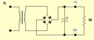
The diode rectifier can be connected directly to a 220 volt network or after a step-down transformer, but its connection circuit remains unchanged.
When a signal arrives in each half-cycle, current will only be able to flow through its own pair of diodes, and the opposite pair will be blocked for it. For a positive half-cycle, VD2 and VD3 will be open, and for a negative half-cycle, VD1 and VD4. As a result, the output will be a constant signal, but its pulsation frequency will be doubled. In order to reduce the ripple of the output signal, a parallel connection of capacitor C1 is used, as in the case of one diode. Such a capacitor is also called a smoothing capacitor.
But it happens that the diode bridge is placed not only in an alternating network, but is also connected to an already rectified one. Why a diode bridge is needed in such a circuit will become clear if you pay attention to which circuits use such a connection. These circuits involve the use of radioelements that are sensitive to power reversal. Using a bridge allows for simple but effective foolproof protection. In case of incorrect connection of the power polarity, the radio elements installed behind the bridge will not fail.
Functionality check
This type of electronic device can be checked without desoldering it from the circuit, since no shunting is used in the device designs. In the case of a rectifier assembled from diodes, each diode is checked separately. And in the case of a monolithic case, measurements are carried out on all four of its terminals.
The essence of the test comes down to checking the diodes for a short circuit with a multimeter. To do this, perform the following steps:
- The multimeter switches to diode or resistance vertebrae mode.
- The plug of one wire (black) is inserted into the common socket of the tester, and the second (red) into the resistance test socket.
- With the probe connected to the black wire, touch the first leg, and with the probe of the red wire, touch the third pin. The tester should show infinity, and if you change the polarity of the wires, the multimeter will show the transition resistance.
- The minus of the tester is fed to the fourth leg, and the plus to the third. The multimeter will show resistance; when changing polarity, infinity.
- Minus on the first leg, plus on the second. The tester will show an open transition, and when changing, a closed one.
Such tester readings indicate the serviceability of the rectifier. If you don't have a multimeter, you can use a regular voltmeter. But in this case you will have to supply power to the circuit and measure the voltage on the smoothing capacitor. Its value should exceed the input value by 1.4 times.
Device and design features
The main structural element is a semiconductor. This is a wafer of silicon or germanium crystal, which has two regions of p and n conductivity. Because of this design feature, it is called planar.
When manufacturing a semiconductor, the crystal is processed as follows: to obtain a p-type surface, it is treated with molten phosphorus, and for a p-type surface, it is treated with boron, indium or aluminum. During heat treatment, diffusion of these materials and the crystal occurs. As a result, a region with a p-n junction is formed between two surfaces with different electrical conductivities. The semiconductor obtained in this way is installed in the housing. This protects the crystal from external influences and promotes heat dissipation.
As already mentioned, silicon or germanium crystals are used as the basis for the p-n junction. The former are used much more often, this is due to the fact that in germanium elements the reverse currents are much higher, which significantly limits the permissible reverse voltage (it does not exceed 400 V). While for silicon semiconductors this characteristic can reach up to 1500 V.
In addition, germanium elements have a much narrower operating temperature range, it varies from -60°C to 85°C. When the upper temperature threshold is exceeded, the reverse current sharply increases, which negatively affects the efficiency of the device. For silicon semiconductors, the upper threshold is about 125°C-150°C.
General characteristics of rectifier diodes.
Depending on the value of the maximum permissible forward current, rectifier diodes are divided into small
,
medium
and
high
power:
low power
designed for direct current rectification up to 300mA;
average power
– from 300mA to 10A;
high power
- more than 10A.
According to the type of material used, they are divided into germanium
and
silicon
, but today
silicon
rectifier diodes are most widely used due to their physical properties.
Silicon diodes, compared to germanium diodes, have many times lower reverse currents at the same voltage, which makes it possible to obtain diodes with a very high permissible reverse voltage, which can reach 1000 - 1500V, whereas for germanium diodes it is in the range of 100 - 400V .
The performance of silicon diodes remains at temperatures from -60 to +(125 - 150)º C, and germanium diodes - only from -60 to +(70 - 85)º C. This is due to the fact that at temperatures above 85º C the formation of electronic hole pairs becomes so significant that there is a sharp increase in the reverse current and the efficiency of the rectifier decreases.
Power classification
The power of the elements is determined by the maximum permissible direct current. In accordance with this characteristic, the following classification has been adopted:
- Low-current rectifier diodes, they are used in circuits with a current of no more than 0.3 A. The housing of such devices is usually made of plastic. Their distinctive features are light weight and small dimensions.
- Devices designed for average power can operate with current in the range of 0.3-10 A. Such elements, for the most part, are made of metal housing and equipped with rigid leads. On one of them, namely on the cathode, there is a thread that allows you to securely fix the diode on the radiator used for heat removal.
- Power semiconductor elements, they are designed for direct current over 10 A. Such devices are produced in metal-ceramic or metal-glass housings of the pin type (A in Fig. 4) or tablet type (B).
Principle of operation
The easiest way to explain the principle of operation of rectifier diodes is with an example. To do this, we simulate the circuit of a simple half-wave rectifier (see 1 in Fig. 6), in which power comes from an alternating current source with voltage UIN (graph 2) and goes through VD to the load R.
During the positive half-cycle, the diode is in the open position and passes current through it to the load. When the turn of the negative half-cycle comes, the device is locked and no power is supplied to the load. That is, there is a kind of cutting off of the negative half-wave (in fact, this is not entirely true, since during this process there is always a reverse current, its value is determined by the Irev characteristic).
As a result, as can be seen from graph (3), at the output we receive pulses consisting of positive half-cycles, that is, direct current. This is the principle of operation of rectifying semiconductor elements.
Note that the pulse voltage at the output of such a rectifier is only suitable for powering low-noise loads, an example would be a charger for a flashlight acid battery. In practice, this scheme is used only by Chinese manufacturers in order to reduce the cost of their products as much as possible. Actually, the simplicity of the design is its only pole.
The disadvantages of a single-diode rectifier include:
- Low level of efficiency, since negative half-cycles are cut off, the efficiency of the device does not exceed 50%.
- The output voltage is approximately half that of the input.
- High noise level, which manifests itself in the form of a characteristic hum at the frequency of the supply network. Its reason is asymmetrical demagnetization of the step-down transformer (in fact, this is why for such circuits it is better to use a damping capacitor, which also has its negative sides).
Note that these disadvantages can be somewhat reduced; to do this, it is enough to make a simple filter based on a high-capacity electrolytic capacitor.
The operating principle of such a filter is quite simple. The electrolyte is charged during the positive half-cycle and discharged when the negative half-cycle occurs. The capacitance must be sufficient to maintain the voltage across the load.
The above solution will improve the situation somewhat, but not much; if you power, for example, active computer speakers from such a half-wave rectifier, a characteristic background will be heard in them. To fix the problem, a more radical solution will be required, namely a diode bridge. Let's look at the operating principle of this circuit.
Simple rectifier circuit
Sinusoidal voltage is a periodic signal that varies over time. From a mathematical point of view, it is described by a function in which the origin corresponds to time equal to zero. The signal consists of two half-waves. The half-wave located in the upper part of the coordinates relative to zero is called a positive half-cycle, and in the lower part - negative.
When an alternating voltage is applied to the diode through a load connected to its terminals, current begins to flow. This current is due to the fact that at the moment the positive half-cycle of the input signal arrives, the diode opens. In this case, a positive potential is applied to the anode and a negative potential to the cathode. When the wave changes to a negative half-cycle, the diode is turned off, as the polarity of the signal at its terminals changes.
Thus, it turns out that the diode, as it were, cuts off the negative half-wave, without passing it to the load, and a pulsating current of only one polarity appears on it. Depending on the frequency of the applied voltage, and for industrial networks it is 50 Hz, the distance between the pulses also changes. This type of current is called rectified, and the process itself is called half-wave rectification.
By rectifying the signal using a single diode, you can power a load that does not have special requirements for voltage quality. For example, a filament. But if you power up, for example, a receiver, a low-frequency hum will appear, the source of which will be the gap that occurs between the pulses. To some extent, to get rid of the disadvantages of half-wave rectification, a capacitor connected in parallel with the load is used together with a diode. This capacitor will charge when pulses arrive and discharge when there are no pulses to the load. This means that the larger the capacitance value of the capacitor, the smoother the current across the load will be.
But the highest signal quality can be achieved if two half-waves are used simultaneously for rectification. The device that allows this to be realized is called a diode bridge, or in other words, a rectifier bridge.
Electrical parameters
Each type of diode has its own operating and maximum permissible parameters, according to which they are selected for operation in a particular circuit:
- Irev – constant reverse current, µA;
- Upr – constant forward voltage, V;
- Ipr max – maximum permissible forward current, A;
- Urev max – maximum permissible reverse voltage, V;
- Р max – maximum permissible power dissipated by the diode;
- Operating frequency, kHz;
- Operating temperature, C.
Circuit of a simple AC rectifier using one diode
We will apply AC mains voltage to the input of the rectifier, in which positive half-cycles are highlighted in red and negative half-cycles are highlighted in blue. We will connect a load (Rн) to the output of the rectifier, and a diode (VD) will perform the function of the rectifying element. With positive half-cycles of voltage applied to the anode of the diode, the diode opens. At these moments of time, a forward diode current Ipr flows through the diode, and therefore through the load (Rн), powered by the rectifier (the half-cycle wave is shown in red in the right graph).
With negative half-cycles of voltage supplied to the anode of the diode, the diode closes, and a slight reverse diode current (Irev) will flow throughout the entire circuit. Here, the diode seems to cut off the negative half-wave of the alternating current (in the right graph, such a half-wave is shown by a blue dotted line).
As a result, it turns out that through the load (Rн), connected to the network through a diode (VD), it is no longer alternating current, since this current flows only in positive half-cycles, and the pulsating current is a current of one direction. This is AC rectification. But this voltage can only power a low-power load that is powered by an AC mains and does not have any special power requirements, for example, an incandescent lamp.
Not all diode parameters are given here, but, as a rule, if you need to find a replacement, then these parameters are sufficient.
Educational program KO. Lecture No. 1 Electric current rectification circuits.
Electric current rectification circuits. Electric current rectifier
– an electronic circuit designed to convert alternating electric current into direct (unipolar) electric current. In semiconductor equipment, rectifiers are made using semiconductor diodes. In older and high-voltage equipment, rectifiers are made using electric vacuum devices - kenotrons. Previously, selenium rectifiers were widely used.
First, let's remember what alternating electric current is. This is a harmonic signal that changes its amplitude and polarity according to a sinusoidal law. In alternating electric current, positive and negative half-cycles can be conventionally distinguished. Everything that is greater than the zero value refers to positive half-cycles (positive half-wave - in red), and everything that is less (below) the zero value - to negative half-cycles (negative half-wave - blue).
The rectifier, depending on its design, “cuts off” or “turns over” one of the half-waves of the alternating current, making the direction of the current one-way.
Circuits for constructing mains voltage rectifiers can be divided into single-phase and three-phase, half-wave and full-wave.
For convenience, we will assume that the rectified alternating electric current comes from the secondary winding of the transformer. This is also true because even the electric current in the home sockets of apartments and houses comes from the transformer of the step-down substation. In addition, since current strength is a quantity that directly depends on the load, when considering rectification circuits we will not operate with the concept of current strength, but with the concept of voltage, the amplitude of which does not directly depend on the load.
The figure shows a circuit and timing diagram for rectifying alternating current with a single-phase half-wave rectifier. The figure shows that the diode cuts off the negative half-wave. If we turn the diode over, swapping its terminals - the anode and cathode, then at the output it turns out that not the negative, but the positive half-wave is cut off. The average voltage value at the output of a half-wave rectifier corresponds to the value: Uav = Umax / π = 0.318 Umax
where: π is a constant equal to 3.14. Half-wave rectifiers are used as mains voltage rectifiers in circuits that consume low current, and also as switching power supply rectifiers. They are absolutely unsuitable as sinusoidal mains voltage rectifiers for devices that consume high current.
The most common are single-phase full-wave rectifiers. There are two circuits of such rectifiers - a bridge circuit and a balanced circuit.
Let's consider the bridge circuit of a single-phase full-wave rectifier and its operation. If the current of the secondary winding of the transformer flows in the direction from point “A” to point “B”, then from point “B” the current flows through diode VD3 (diode VD1 does not pass it), load Rн, diode VD2 and returns to the transformer winding through point "A". When the direction of the current in the secondary winding of the transformer changes to the opposite, the current leaving point “A” flows through diode VD4, load Rн, diode VD1 and returns to the transformer winding through point “B”.
Thus, there is practically no time period when the voltage at the rectifier output is zero.
Let's consider a balanced circuit of a single-phase full-wave rectifier. At its core, these are two half-wave rectifiers connected in parallel in antiphase, with the beginning of the second winding connected to the end of the first secondary winding. If in a bridge circuit one secondary winding of the transformer is used during both half-cycles of the mains voltage, then in a balanced circuit two secondary windings (2 and 3) are used alternately.
The average voltage value at the output of the full-wave rectifier corresponds to the value: Uav = 2*Umax / π = 0.636 Umax
where: π is a constant equal to 3.14. Of interest is the combination of a bridge and balanced rectification circuit, as a result of which a bipolar bridge rectifier is obtained, in which one wire is common for two output voltages (for the first output voltage, it is negative, and for the second, it is positive): Three-phase rectifiers
Three-phase rectifiers have better AC rectification characteristics - a lower output voltage ripple factor compared to single-phase rectifiers. This is due to the fact that in a three-phase electric current, sinusoids of different phases “overlap” each other. After rectifying such a voltage, the amplitudes of different phases are not added together, but the maximum amplitude is isolated from the values of all three phases of the input voltage. The following figure shows the circuit of a three-phase half-wave rectifier and its output voltage (in red), formed at the “peaks” of the three-phase voltage. Due to the “overlapping” of the voltage phases, the output voltage of a three-phase half-wave rectifier has a smaller ripple depth. The secondary windings of the transformer can only be used in a star connection, with a “zero” terminal from the transformer.
The following figure shows the circuit of a three-phase full-wave bridge rectifier (Larionov circuit) and its output voltage (in red). By using the positive and inverted negative half-waves of three-phase voltage, the output voltage (highlighted in red) generated at the vertices of the sinusoids has the smallest output voltage ripple depth compared to all other rectification circuits. The secondary windings of the transformer can be used either according to the “star” connection scheme, without the “zero” terminal from the transformer, or “delta”. When designing power supplies, the following parameters are used to select rectifier diodes, which are always indicated in reference books:
— maximum diode reverse voltage – Urev
;
— maximum diode current – Imax
;
— forward voltage drop across the diode – Upr
.
It is necessary to select all of these listed parameters with a margin to prevent diode failure.
Maximum diode reverse voltage Urev
should be twice the actual output voltage of the transformer.
Otherwise, a pn
, which can lead to failure of not only the rectifier diodes, but also other elements of the power and load circuits.
Maximum current value Imax
The selected diodes should exceed the actual rectifier current by 1.5 - 2 times. Failure to comply with this condition also leads to failure of first the diodes, and then other circuit elements.
Forward voltage drop across the diode – Upr
, this is the voltage that drops across
p-n
junction crystal.
If there are two diodes along the current path, then this drop occurs at two p-n
junctions. In other words, the voltage applied to the rectifier input is reduced by the voltage drop at the output.
Rectifier circuits are designed to convert an alternating voltage that changes the polarity into a unipolar voltage that does not change the polarity. But this is not enough to convert alternating voltage into direct voltage. In order for it to be converted into a constant voltage, it is necessary to use smoothing power filters that eliminate sudden changes in the output voltage from zero to the maximum value.