The ferrite tube has one great advantage - it is easy to find it on the signal cable of an old CRT monitor or buy such a cable at a computer store. Possessing sufficient bandwidth for HF (about 1-30 MHz), it makes it possible to sell antennas for the transceiver at a lower price. Principle of counting the number of turns:
Blue wire - 1 turn,
Red wire - 1.5 turns.
Balancing transformer on ferrite tubes 50 / 300 Ohm
We start by winding 2.5 turns (blue), based on the required resistance of 300 Ohms. We connect the other end of the wire to ground at the input connection level. This will be the common point of mass. Starting from the mass point, we wind new 2.5 turns of wire (green), which complete the 300 Ohm winding. Again starting from the ground point, we wind 2 more turns of wire (red), which we connect to the input connector (PL). The diameter of the wire is determined by the ability to fit the windings in a ferrite tube.
Note: Use as thick a wire as possible.
Filling the entire hole. By completely and uniformly filling the core window, you can achieve less “blockage” in the HF ranges. Brief conclusions.
If you want to have more power of the device, you should strive not to increase the number of tubes, but to increase the cross-section of each tube. And the number of tubes should be minimal, i.e. only 2, but “thick”!
Do not forget that the greater the reactive component in the load, the worse it is for the transformer. Following this principle, we can carry out various coordinations, observing the number of turns in accordance with the table:
At equivalent load, the measured SWR does not exceed 1.5 (in the range from 1 to 30 MHz).
The measured loss was 0.4 dB.
(Note UA4AEU - you can achieve an SWR of 1.1 by compensating the reactance with a small capacitance at the input or output of the balun (selected experimentally at the highest frequency).
When connected to an antenna, there may be a slight shift in the antenna's resonant frequency. Based on the size, the winding can be made of enameled rigid wire. It is easier to make a winding from a flexible insulated wire.
How to calculate and wind a pulse transformer for a half-bridge power supply?
We will talk about “lazy winding”. This is when you are too lazy to count the turns. https://site/
Selecting the type of magnetic circuit.
The most universal magnetic cores are W-shaped and cup-shaped armor cores. They can be used in any switching power supply, thanks to the ability to set a gap between the parts of the core. But, we are going to wind a pulse transformer for a push-pull half-bridge converter, the core of which does not need a gap and therefore a ring magnetic circuit is quite suitable. https://site/
For a ring core there is no need to make a frame and make a winding device. The only thing you have to do is make a simple shuttle.
The picture shows a ferrite magnetic core M2000NM.
The standard size of the ring magnetic core can be identified by the following parameters.
D is the outer diameter of the ring.
d – internal diameter of the ring.
Literature.
- Kosenko S. “Calculation of a pulse transformer of a push-pull converter” // Radio, No. 4, 2005, p. 35 - 37, 44.
- Eranosyan S. A. Network power supplies with high-frequency converters. — L.: Energoatomizdat. Leningr. department, 1991, - 176 p.: ill.
- S. V. Kotenev, A. N. Evseev. Calculation and optimization of toroidal transformers and chokes. - M.: Hotline-Telecom, 2013. - 359 p.: ill.
- A. Petrov “Inductances, chokes, transformers” // Radio Amateur, No. 12, 1995, pp. 10-11.
- Mikhailova M.M., Filippov V.V., Muslakov V.P. Soft magnetic ferrites for electronic equipment. Directory. - M.: Radio and Communications, 1983. - 200 p., ill.
- Calculated geometric parameters of ring cores.
- B.Yu. Semenov. Power electronics for amateurs and professionals. M.: Solon-R, 2001. - 327 p. : silt
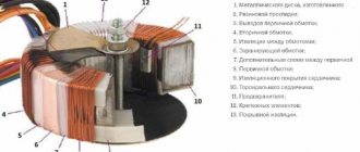
Various types of transformer equipment are used in electronic and electrical circuits, which are in demand in many areas of economic activity. For example, pulse transformers (hereinafter referred to as IT) are an important element installed in almost all modern power supplies.
Obtaining initial data for simple calculation of a pulse transformer.
Supply voltage.
I remember when our power grids had not yet been privatized by foreigners, I built a switching power supply. The work dragged on until night. During the last tests, it suddenly turned out that the key transistors began to get very hot. It turned out that the network voltage jumped to 256 Volts at night!
Of course, 256 Volts is too much, but you shouldn’t rely on GOST 220 +5% –10% either. If you choose 220 Volts +10% as the maximum network voltage, then:
242 * 1.41 = 341.22V
(we count the amplitude value).
341.22 – 0.8 * 2 ≈ 340V
(subtract the drop on the rectifier).
Induction.
We determine the approximate value of induction from the table.
Example: M2000NM – 0.39T.
Frequency.
The generation frequency of a self-excited converter depends on many factors, including the size of the load. If you choose 20-30 kHz, you are unlikely to make a big mistake.
Limit frequencies and induction values of widespread ferrites.
Manganese-zinc ferrites.
| Parameter | Ferrite grade | |||||
| 6000NM | 4000NM | 3000NM | 2000NM | 1500NM | 1000NM | |
| 0,005 | 0,1 | 0,2 | 0,45 | 0,6 | 1,0 | |
| 0,35 | 0,36 | 0,38 | 0,39 | 0,35 | 0,35 | |
Nickel-zinc ferrites.
| Parameter | Ferrite grade | |||||
| 200NN | 1000NN | 600NN | 400NN | 200NN | 100NN | |
| Cutoff frequency at tg δ ≤ 0.1, MHz | 0,02 | 0,4 | 1,2 | 2,0 | 3,0 | 30 |
| Magnetic induction B at Hm = 800 A/m, T | 0,25 | 0,32 | 0,31 | 0,23 | 0,17 | 0,44 |
What ferrites can be used and why?
As is known, the core in a transformer acts as a concentrator of electromagnetic energy. The higher the permissible induction B
and magnetic permeability μ, the greater the density of the transmitted energy and the more compact the transformer. The so-called ones have the greatest magnetic permeability. ferromagnets - various compounds of iron, nickel and some other metals.
The magnetic field is described by two quantities: intensity H (proportional to the winding current) and magnetic induction B (characterizes the force action of the field in the material). The relationship between B and H is called the magnetization curve of a substance. In ferromagnets, it has an interesting feature - hysteresis (Greek: lagging) - when the instantaneous response to an influence depends on its background.
After leaving the zero point (this section is called the main magnetization curve), the fields begin to run along a certain closed curve (called a hystresis loop). Characteristic points are marked on the curve - saturation induction B s, residual induction B r and coercive force H c.
Fig.1. Magnetic properties of ferrites. On the left is the shape of the hysteresis loop and its parameters. On the right is the main magnetization curve of 1500NM3 ferrite at various temperatures and frequencies: 1 - 20 kHz, 2 - 50 kHz, 3 - 100 kHz.
Based on the values of these quantities, ferromagnets are conventionally divided into hard and soft. The former have a wide, almost rectangular hysteresis loop and are good for permanent magnets. And materials with a narrow loop are used in transformers. The fact is that there are two types of losses in the transformer core - electrical and magnetic. Electrical (for excitation of Foucault eddy currents) are proportional to the conductivity of the material and frequency, but magnetic ones are smaller, the smaller the area of the hysteresis loop.
Ferrites are pressed powders of iron oxides or other ferromagnetic materials sintered with a ceramic binder. This mixture combines two opposing properties - the high magnetic permeability of iron and the poor conductivity of oxides. This minimizes both electrical and magnetic losses and allows transformers to be made that operate at high frequencies. The frequency properties of ferrites are characterized by the critical frequency fc, at which the loss tangent reaches 0.1. Thermal - the Curie temperature Tc, at which μ abruptly decreases to 1.
Domestic ferrites are marked with numbers indicating the initial magnetic permeability and letters indicating the frequency range and type of material. The most common is low-frequency nickel-zinc ferrite, designated by the letters NN. It has low conductivity and a relatively high frequency fc. But it has large magnetic losses and a low Curie temperature. Nickel-manganese ferrite is designated NM. Its conductivity is greater, so fc is low. But magnetic losses are small, the Curie temperature is higher, and it is less afraid of mechanical shocks. Sometimes ferrites are labeled with an additional number 1, 2 or 3. Usually, the higher it is, the more temperature stable the ferrite is.
What brands of ferrites are we most interested in?
Thermally stable ferrite 1500NM3 with fc=1.5 MHz, Bs=0.35..0.4 T and Tc=200 ℃ is good for converter technology.
For special applications, ferrite 2000NM3 is produced with standardized desacammodation (temporary stability of magnetic permeability). It has fc=0.5 MHz, Bs=0.35..0.4 T and Tc=200 ℃.
Ferrites of the NMC series have been developed for powerful and compact transformers. For example, 2500NMS1 with Bs=0.45 T and 2500NMS2 with Bs=0.47 T. Their critical frequency is fc=0.4 MHz, and their Curie temperature is Tc>200 ℃.
As for the permissible induction B m, this parameter is adjustable and is not standardized in the literature. Approximately we can consider B m = 0.75 V s min
. For nickel-manganese ferrites this gives approximately 0.25 T. Taking into account the drop in B s at elevated temperatures and due to aging, in critical cases it is better to play it safe and reduce B m to 0.2 T.
The main parameters of common ferrites are summarized in Table 3.
Table 3. Basic parameters of some ferrites
| Brand | 100NN | 400NN | 600NN | 1000NN | 2000NN | 2000NM | 1000NM3 | 1500NM1 | 1500NM3 |
| μ start | 80..120 | 350..500 | 500..800 | 800..1200 | 1800..2400 | 1700..2500 | 800..1200 | 1200..1800 | 1200..1800 |
| fc, MHz | 7 | 3,5 | 1,5 | 0,4 | 0,1 | 0,5 | 1,8 | 0,7 | 1,5 |
| Tc, ℃ | 120 | 110 | 110 | 110 | 70 | 200 | 200 | 200 | 200 |
| Bs, T | 0,44 | 0,25 | 0,31 | 0,27 | 0,25 | 0,38..0,4 | 0,33 | 0,35..0,4 | 0,35..0,4 |
How to choose ferrite ring core?
You can select the approximate size of a ferrite ring using a calculator for calculating pulse transformers and a guide to ferrite magnetic cores. You can find both of them in.
We enter the data of the proposed magnetic core and the data obtained in the previous paragraph into the calculator form to determine the overall power of the core.
You should not choose ring dimensions close to the maximum load power. It is not so convenient to wind small rings, and you will have to wind a lot more turns.
If there is enough free space in the body of the future design, then you can choose a ring with a obviously larger overall power.
I had at my disposal an M2000NM ring of standard size K28x16x9mm. I entered the input data into the calculator form and received an overall power of 87 watts. This is more than enough for my 50 Watt power supply.
Launch the program. Select “Calculation of a half-bridge transformer with a master oscillator.”
To prevent the calculator from “swearing”, fill in the windows not used for calculating the secondary windings with zeros.
How to disassemble correctly
Despite the fact that at first glance the transformer seems to be a complex device, its disassembly is quite simple to perform. The main task in this case is to remove the surface shell consisting of a ferrite magnetic core.
To do this, you need to heat the ferrite to 300 0 C and loosen the existing halves and pull them out of the frame. This must be done quickly so that the softened glue does not have time to harden. This procedure must be performed with gloves. Next you will need:
- bite off the attached copper windings with pliers;
- unwind the wire to the very base;
- remove the remaining pieces of winding from the frame.
Just a few steps and the transformer frame is completely cleaned. The main difficulty is heating the ferrite shell. But in this case, you can use several tips. For example, use a hair dryer, a soldering station, or heat it in a frying pan.
How to calculate the number of turns of the primary winding?
We enter the initial data obtained in the previous paragraphs into the calculator form and obtain the number of turns of the primary winding. By changing the size of the ring, the grade of ferrite and the generation frequency of the converter, you can change the number of turns of the primary winding.
It should be noted that this is a very, very simplified calculation of a pulse transformer.
But, the properties of our wonderful self-excited power supply are such that the converter itself adapts to the parameters of the transformer and the load size by changing the generation frequency. So, as the load increases and the transformer tries to enter saturation, the generation frequency increases and the operation returns to normal. Minor errors in our calculations are compensated in the same way. I tried to change the number of turns of the same transformer by more than one and a half times, which is reflected in the examples below, but I could not detect any significant changes in the operation of the power supply, except for a change in the generation frequency.
Calculation method and example
One of the simplest ways to make calculations regarding winding wiring on a pulse transformer is to use special programs. Thanks to this, you can find out how many turns will need to be made, and what materials are best to use for this. For example, you can give the following calculation:
- If we take the conversion frequency of 50 kHz as a basis, this is the case when the transformer will be remade for a PC power supply, then in the program you need to note the indicators at 30 kHz.
- Then you need to indicate the dimensions and, accordingly, the parameters of the core.
How to wind a pulse transformer?
First you need to prepare the ferrite ring.
To prevent the wire from cutting through the insulating gasket and damaging itself, it is advisable to dull the sharp edges of the ferrite core. But, this is not necessary, especially if the wire is thin or a reliable gasket is used. True, for some reason I always do this.
Using sandpaper, round the outer sharp edges.
We do the same with the inner faces of the ring.
To prevent breakdown between the primary winding and the core, an insulating gasket should be wound around the ring.
As an insulating material, you can choose varnished cloth, fiberglass cloth, keeper tape, Mylar film or even paper.
When winding large rings using wire thicker than 1-2mm, it is convenient to use keeper tape.
Sometimes, when making homemade pulse transformers, radio amateurs use fluoroplastic tape - FUM, which is used in plumbing.
It is convenient to work with this tape, but fluoroplastic has cold fluidity, and the pressure of the wire in the area of the sharp edges of the ring can be significant.
In any case, if you are going to use FUM tape, then lay a strip of electrical cardboard or plain paper along the edge of the ring.
When winding gaskets onto small rings, it is very convenient to use a mounting hook.
The mounting hook can be made from a piece of steel wire or a bicycle spoke.
Carefully wrap the insulating tape around the ring so that each turn overlaps the previous one on the outside of the ring. Thus, the insulation on the outside of the ring becomes two-layer, and on the inside - four or five layers.
To wind the primary winding we need a shuttle. It can be easily made from two pieces of thick copper wire.
The required winding wire length is quite easy to determine. It is enough to measure the length of one turn and multiply this value by the required number of turns. A small allowance for conclusions and calculation errors will also not hurt.
34
(mm)
* 120
(turns)
* 1.1
(times) =
4488
(mm)
If a wire thinner than 0.1 mm is used for the winding, then stripping the insulation with a scalpel can reduce the reliability of the transformer. It is better to remove the insulation of such a wire using a soldering iron and an aspirin tablet (acetylsalicylic acid).
Be careful! When acetylsalicylic acid melts, toxic fumes are released!
If a wire with a diameter of less than 0.5 mm is used for any winding, then it is better to make the terminals from stranded wire. We solder a piece of stranded insulated wire to the beginning of the primary winding.
We insulate the soldering area with a small piece of electrical cardboard or ordinary paper with a thickness of 0.05 ... 0.1 mm.
We wind the beginning of the winding so as to securely secure the junction.
We perform the same operations with the output of the end of the winding, only this time we secure the junction with cotton threads. To prevent the tension of the thread from weakening while tying a knot, we secure the ends of the thread with a drop of melted rosin.
If a wire thicker than 0.5 mm is used for the winding, then the conclusions can be made with the same wire. At the ends you need to put pieces of polyvinyl chloride or other tube (cambric).
Then the leads together with the tube need to be secured with cotton thread.
We wrap two layers of varnished cloth or other insulating tape over the primary winding. This interwinding gasket is necessary for reliable isolation of the secondary circuits of the power supply from the lighting network. If you use a wire with a diameter of more than 1 millimeter, then it is a good idea to use keeper tape as a gasket.
If you intend to use it, then you can wind the secondary winding in two wires. This will ensure complete symmetry of the windings. The turns of the secondary windings must also be evenly distributed around the perimeter of the core. This is especially true for the most powerful windings in terms of power take-off. The secondary windings, which take away a small amount of power compared to the total, can be wound at random.
If you don’t have a wire of sufficient cross-section at hand, you can wind the winding with several wires connected in parallel.
The picture shows a secondary winding wound in four wires.
In order for the feeder to be matched with the antenna, matching devices (MD) are used - in amateur radio slang, “ balun”
” (BALUN – balanced/unbalanced, i.e. symmetrical/asymmetrical). To be completely precise, control systems come in different “symmetrical-asymmetrical” combinations (BALUN, BALBAL, UNUN). The unbalanced input is connected to a coaxial feeder or an unbalanced antenna (LW, for example). The balanced input is connected to a two-wire feeder or a balanced antenna (for example, a dipole). The adjustable matching device is often called an antenna tuner (which sometimes functions as a preselector).
The most popular control systems are in the form of broadband matching transformers, the windings of which form a long line. The ratio of winding resistances is calculated by the formula: R1=k^2*R2, where k is the transformation ratio (the ratio of the number of turns of the primary winding to the number of turns of the secondary).
Abroad, two types of broadband transformers have entered amateur radio practice: Guanella (current) and Ruthroff (voltage), according to the names of the authors of the relevant articles: 1. Guanella, G., “Novel Matching Systems for High Frequencies”, Brown-Boveri Review, Vol 31, Sep 1944, pp. 327-329. 2. Ruthroff, C. L., “Some Broad-Band Transformers,” Proc IRE, Vol 47, August 1959, pp. 1337-1342.
In the USSR, V.D. is known for his publications on broadband transformers. Kuznetsov.
Nowadays, wideband transformers (BCTs, “baluns”) on ferrite rings, rods or “binoculars” are popular. But there are also SHPTs without ferrite cores. Ferrite cores, as a rule, do not work as a magnetic circuit at high frequencies (carbonyl cores work at HF), and current transformation occurs due to mutual induction (magnetic coupling) of the windings. In this case, the ferrite core only increases the inductance of the windings. A balun with a 1:1 ratio is usually a conventional RF choke, although there are also baluns.
When it is necessary to combine a minimum dissipation factor with a minimum throughput capacitance, it is recommended to use transformers with volumetric turns. The relative width of the operating range is 10-15 (the ratio of the upper frequency to the lower frequency).
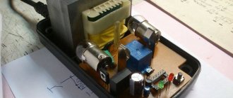
Assembling a switching power supply with your own hands: step-by-step instructions and diagrams
Often, radio amateurs have to build a switching power supply with their own hands to power circuits and devices from the network.
Step-by-step instructions will help you understand how switching power supplies work, which are preferable to use, compact, but more complex than conventional transformer ones.
Device
As in a conventional power supply, in a pulsed one the main components are a transformer and a rectifier.
Operating principle of the power supply
The function of the device consists of two actions:
In addition to the mentioned nodes, the pulse power supply also contains the so-called. inverter: a circuit that converts direct current into alternating current with a frequency much higher than the network one - tens of kHz.
Features of work
The reason for the complexity of the circuit is the following: the higher the frequency of the alternating current, the smaller the transformer required and the lower the losses in it. This is why switching power supplies are much smaller than their regular counterparts.
Scheme
The pulse power supply consists of the following functional blocks:
- filter _ Does not allow interference from the network and back (generated by the power supply itself);
- rectifier with smoothing capacitor . A conventional diode bridge produces an almost even (with low ripple coefficient) output constant voltage equal to the effective value of the alternating mudflow voltage - 311 V;
- inverter _ It consists of quickly switching power key transistors and a microcircuit that controls them. The output gives a rectangular alternating current. The conversion process in the inverter is called pulse width modulation (PWM), and the chip is called a PWM controller. In operating mode, feedback is implemented, therefore, depending on the power of the load connected to the power supply, the controller regulates the duration of the opening of the transistors, that is, the width of the pulses. Also, thanks to feedback, input voltage surges and surges caused by switching powerful consumers are compensated. This ensures high quality output voltage;
- pulse high frequency transformer . Lowers the voltage to the required 12 or 24 V;
- rectifier with smoothing capacitor . Converts high-frequency alternating voltage to direct voltage.
AC choke
The main element of a surge protector is a choke. Its resistance (inductive) increases with increasing frequency of the current, therefore high-frequency interference is neutralized, and current with a frequency of 50 Hz passes freely.
The larger the size of the magnetic circuit, the thickness of the wire and the more turns, the more efficient the choke is.
Additional installed capacitors improve filtering by short-circuiting high-frequency interference and diverting it to ground.
Also, capacitive reactances prevent RF interference generated by the power supply from entering the network. A high-frequency transformer differs from a conventional transformer in the material of its magnetic core: ferrites or alsifer are used. The rectifier after the transformer is assembled using Schottky diodes, which are characterized by high performance.
There are two ways to generate high frequency alternating current:
- single-ended circuit . It is used in low-power power supplies - up to 50 W (charging phones, tablets, etc.). The design is simple, but it has a large voltage amplitude on the primary winding of the transformer (protected by resistors and capacitors);
- push-pull circuit . The device is more complex, but it is more economical (higher efficiency). The push-pull circuit is divided into three types: full-wave . The simplest option;
- bipolar . It differs from the previous one in the presence of 2 additional diodes and a smoothing capacitor. The flyback principle of operation is implemented. Such circuits are widely used in power amplifiers. An important feature: the service life of capacitors is extended due to the fact that lower currents flow through them;
- linear _ Used in high-power power supplies (PCs, etc. devices). It is distinguished by the presence of a large inductor that accumulates the energy of PWM pulses (directed to it through two diodes that ensure the same polarity).
2-stroke power supplies differ in the power stage circuit; there are three modifications:
- half-bridge : sensitive to overloads, therefore requiring complex protection;
- pavement : more economical, but difficult to set up;
- push- pull The most economical and therefore in great demand, especially in powerful power supplies. It is distinguished by the presence of a middle terminal on the primary and secondary windings of the transformer. During the period, first one or the other half-winding works, connected by the corresponding key transistor.
Stabilization of the output voltage is achieved in the following ways:
- using an additional winding on the transformer. This is the simplest method, but also the least effective. The voltage removed from it corrects the signal on the primary winding;
- using an optocoupler. This is a more efficient way. The main elements of an optocoupler are an LED and a phototransistor. The circuit is designed so that the current flowing through the LED is proportional to the output voltage. The glow of the diode controls the operation of the phototransistor, which supplies signals to the PWM controller.
Thus, in this technique, the voltage on the secondary winding is directly controlled, and there is no galvanic connection with the key stage generator.
When connected in series with a zener diode optocoupler, the quality of stabilization becomes even higher.
Step-by-step instruction
The manufacturing process of a switching power supply looks like this:
- They calculate the product using an online calculator (published on many websites) or a special program. Depending on the desired characteristics of the power supply, the software will select the parameters of all elements: capacitors, transistors, chokes, etc.;
- purchase all radio components;
- Holes are drilled in the PCB plate in accordance with the diagram and dimensions of the elements. It is not always possible to achieve the desired characteristics the first time, which is why the circuit has to be supplemented with compensators and other elements. It is necessary to leave space for them on the board;
- in the diagram, select the entry points marked with the symbols “AC”, solder the fuse and then, one by one, all the elements according to the diagram;
- perform a check.
It is important to find a suitable scheme and correctly calculate the parameters of the elements.
UPS on a chip
There are many microcircuits with PWM controller function available. Below we discuss several schemes using the most popular ones.
TL494
Since the built-in switches of this microcircuit do not have sufficient power to directly control the inverter’s power transistors (T3 and T4), an intermediate link is introduced from transformer TR1 (control) and transistors T1, T2.
Circuit on a TL494 chip
If you have an old power supply from a computer, the control transformer can be taken from there. The composition of the windings is left unchanged. It is recommended to use MJT13009 bipolar transistors as power ones - the circuit will be more reliable. When using MJE13007 transistors, designed for lower current, the circuit will work, but it will be too sensitive to overloads.
Chokes L5, L6 are also removed from the broken computer power supply. The first one is rewound, since in the original design it is designed for several voltage levels.
About 50 turns of copper wire with a diameter of 1.5 mm are wound around the yellow magnetic core (others will not work) in the form of a ring.
Power transistors T3, T4 and diode D15 get very hot during operation, so they are installed on radiators.
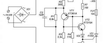
IR2153
Of all the microcircuits, this one is the cheapest, which is why many people prefer to assemble power supplies on it. Here the driver is connected not to the +310 V bus, but through a resistor to the network. With this connection, the power released by the resistor is reduced.
Circuit on IR2153 chip
The scheme provides:
- starting current limitation (soft start or soft start). The component is powered from the network through quenching capacitor C2;
- short circuit and overload protection. Resistance R11 is used as a current sensor. The protection operation current is regulated by trimming resistance R10.
The HL1 LED indicates that the protection has been triggered. The output voltage is up to 70 V, with dual polarity. The number of turns on the primary winding of the pulse transformer is 50, on each of the 4 secondary windings - 23. The choice of the cross-section of wires in the windings and the type of core depends on the desired power.
UC3842
Another inexpensive microcircuit, but very reliable and therefore very popular. When turned on, the current charging capacitor C2 is limited by thermistor R1.
Circuit on UC3842 chip
The resistance of the latter at this moment is 4.7 Ohms, then as it warms up it decreases by an order of magnitude, after which this element from the circuit seems to be “turned off”. Stabilization of the output voltage is due to feedback (loop “secondary winding of transformer T1 – diode VD6 – capacitor C8 – resistor R6 – diode VD5”).
The loop voltage is set by a resistive divider R2 – R3. Chain “R4 – C5” is a timer for the internal pulse generator UC3842. The PWM controller and other microcircuits are installed on plate radiators with an area of at least 5 square meters. cm.
Examination
Check a homemade switching power supply like this:
- connect the leads from the microcircuit to a 40 W lamp;
- connect the device to the network. The lamp will blink faintly;
- use a multimeter to check whether the output voltage matches the desired one;
- check the pulse on the key gates with a multimeter;
- measure the DC voltage on the smoothing capacitors. Normally, it is 1.5 - 2 times higher than the alternating voltage on the diode bridge.
If all values are correct, turn on the power supply with full load.
on this topic
How to make a simple switching power supply with your own hands:
There are many options for switching power supplies. The presented circuits are quite reliable, produce a stable voltage and at the same time are available for manufacturing by an amateur. It is important to remember the dangers of working with electricity and do not hesitate to consult with specialists in doubtful cases.
Transformers with volumetric turns (inductive loop)
Transformer design with volumetric turn
Such a transformer is characterized by high symmetry, since the capacitive coupling between its windings is minimized.
The connection between the primary and secondary windings, located on ring ferrite cores with high magnetic permeability, is carried out using a volumetric coil (inductive loop) formed by the transformer body (screen) and a rod - a bolt that tightens the entire structure.
However, due to the fact that the transformer connection between the primary and secondary windings is carried out through a volumetric turn formed by a metal partition, metal cups and a rod, such a transformer is not capable of transmitting significant power due to Foucault currents (the copper “volumetric turn” is heated by eddy currents).
Such a transformer was used on the R-140 radio station as a balun transformer for the receiving V-antenna.
Transformers with external turn
(on ferrite tubes “binoculars”) work due to the mutual induction of the windings. The ferrite core, in this case, must have a higher magnetic permeability to increase the inductance of the windings. The core does not work here as a magnetic circuit.
Bifilar wound spool for 4:1 balun
Ferrites have two main properties: magnetic permeability and resistivity. The higher the resistivity, the lower the eddy current losses, the less the core heats up.
Baluns with an “air core” (i.e., without a core at all) have a number of advantages over ferrite ones. They are less demanding for installation, can withstand greater power and are easier to manufacture. However, compared to ferrite transformers, they have a narrower operating frequency range.
How to reel correctly
Before you start winding the transformer, you should remember that this work is painstaking if the work is done manually. The whole point is that the turns should fit tightly to each other. The best option would be to use a primitive device that you can make yourself. It must also be said that winding the wire should be done solely on the basis of calculations. That is, the exact number of turns directly in one layer.
Each layer must be separated from the next row of turns with a special insulating tape. If there is none, then you can use thin but thick paper.
For example, you can use tracing paper. Often the winding consists of three layers, and each of them must be insulated from each other. At the end of the winding process, the wiring terminals must be properly soldered.
It is important to know! The insulating material used must not only be dense, but it is important that it is not damaged. This is due to the fact that there is no possibility of a short circuit.
Core selection
As for the choice of core, in order to save money, you can use the old one. If a new one is required, it must be made of appropriate material. For example, cores based on amorphous magnetic alloys are suitable for a personal computer.
Winding the primary winding
Initially, you need to prepare all the relevant materials. This is the transformer frame, wire of the required diameter and insulating material. The winding should begin from the very edge of the core; it is advisable to wind it clockwise. The coils should be even and tightly adjacent to each other. There should be no gaps. Do not forget to provide adequate insulation between layers.
Winding the secondary winding
Secondary winding is carried out according to the same principle as primary winding. At the end of winding, you must definitely leave a tail of the wire, which must be insulated. Afterwards you need to solder it to the corresponding contacts.
It is important to know! The turns of the first layer must be separated from each other by one layer of insulating material, which is coated with glue.
Between the primary and secondary winding layers, insulation should be made of at least 4-5 layers. In this way, breakdowns and, accordingly, short circuits in the converted transformer can be avoided.
Design (types) of pulse transformers
Depending on the shape of the core and the placement of coils on it, ITs are produced in the following designs:
- core;
- armored;
- toroidal (has no coils, the wire is wound on an insulated core);
- armored rod;
The figures indicate:
- A – magnetic circuit made of transformer steel grades made using cold or hot metal rolling technology (with the exception of the toroidal core, it is made of ferrite);
- B – coil made of insulating material
- C – wires creating inductive coupling.
Note that electrical steel contains few silicon additives, since it causes power loss from the effect of eddy currents on the magnetic circuit. In toroidal IT, the core can be made from rolled or ferrimagnetic steel.
The plates for the electromagnetic core set are selected in thickness depending on the frequency. As this parameter increases, it is necessary to install thinner plates.
Tips and tricks
Before rewinding a pulse transformer, you need to take into account some nuances. The main ones are:
- If the transformer makes a hum, this is not the cause of the malfunction. In some specific devices, this is considered normal.
- If sparks or crackling sounds occur, this is a clear malfunction.
- The operation of the windings may change not due to malfunctions, but due to simple contamination of the device. This can be corrected by cleaning the contacts.
As a recommendation, it must be said that it is forbidden to connect direct voltage to the windings, since the wire used for the winding will simply melt. It is important to make appropriate measurements before starting rewinding, which will allow the work to be completed efficiently. Learning this is quite simple, but you need to be careful and follow all the indicated recommendations.
Principle of operation
The main feature of pulse-type transformers (hereinafter referred to as IT) is that they are supplied with unipolar pulses with a constant current component, and therefore the magnetic circuit is in a state of constant magnetization. Below is a schematic diagram of connecting such a device.
Diagram: connecting a pulse transformer
As you can see, the connection diagram is almost identical to conventional transformers, which cannot be said about the timing diagram.
The primary winding receives pulse signals having a rectangular shape e (t), the time interval between which is quite short. This causes the inductance to increase during the interval tu, after which its decline is observed in the interval (T-tu).
Induction changes occur at a speed that can be expressed in terms of a time constant using the formula: τ p =L 0 /R n
The coefficient describing the difference in the inductive differential is determined as follows: ∆V=V max – V r
- В max – level of maximum induction value;
- In r – residual.
The difference in induction is shown more clearly in the figure, which shows the displacement of the operating point in the magnetic conductor circuit of the IT.
As can be seen in the timing diagram, the secondary coil has a voltage level U 2 in which reverse emissions are present. This is how the energy accumulated in the magnetic circuit manifests itself, which depends on magnetization (parameter iu).
The current pulses passing through the primary coil are trapezoidal in shape, since the load and linear currents (caused by the magnetization of the core) are combined.
The voltage level in the range from 0 to tu remains unchanged, its value e t =U m. As for the voltage on the secondary coil, it can be calculated using the formula:
wherein:
- Ψ – flux linkage parameter;
- S is a value that reflects the cross-section of the magnetic core.
Considering that the derivative, which characterizes changes in the current passing through the primary coil, is a constant value, the increase in the induction level in the magnetic circuit occurs linearly. Based on this, it is permissible, instead of the derivative, to enter the difference between the indicators taken over a certain time interval, which allows you to make changes to the formula:
in this case, ∆t will be identified with the parameter tu, which characterizes the duration with which the input voltage pulse occurs.
To calculate the area of the pulse with which the voltage is generated in the secondary winding of the IT, it is necessary to multiply both parts of the previous formula by tu. As a result, we arrive at an expression that allows us to obtain the main IT parameter:
U mxtu =S x W 1 x ∆V
Note that the magnitude of the pulse area directly depends on the parameter ∆B.
The second most important quantity characterizing the operation of IT is the induction drop; it is influenced by such parameters as the cross-section and magnetic permeability of the magnetic core, as well as the number of turns on the coil:
Here:
- L 0 – induction difference;
- µ a – magnetic permeability of the core;
- W 1 – number of turns of the primary winding;
- S – cross-sectional area of the core;
- l cр – length (perimeter) of the core (magnetic core)
- In r – the value of residual induction;
- In max – the level of the maximum induction value.
- H m – Magnetic field strength (maximum).
Considering that the inductance parameter of the IT completely depends on the magnetic permeability of the core, when calculating it is necessary to proceed from the maximum value of µ a, which is shown by the magnetization curve. Accordingly, for the material from which the core is made, the level of the parameter B r, which reflects the residual induction, should be minimal.
Video: detailed description of the operating principle of a pulse transformer
Based on this, a tape made of transformer steel is ideal as an IT core material. You can also use permalloy, which has a minimum squareness coefficient.
Cores made of ferrite alloys are ideal for high-frequency IT, since this material has low dynamic losses. But due to its low inductance, IT has to be made in large sizes.
How hot will the core get?
Losses in magnets.
At a frequency less than critical fс, energy losses in the magnet consist mainly of losses due to magnetization reversal, and eddy current losses can be neglected. Experience and theory show that energy losses per unit volume (or mass) during one magnetization reversal cycle are directly proportional to the area of the hysteresis loop. Therefore, the power of magnetic losses:
PH = P 0 ⋅ V ⋅ f
(8)
Where P 0
– specific losses per unit volume (measured at frequency
f 0
with induction
B 0
),
V
– sample volume.
However, with increasing frequency, the saturation induction decreases, the hysteresis loop is deformed, and losses increase. To take these factors into account, Steinmetz (CP Steinmetz, 1890-1892) proposed an empirical formula:
PH = P 1 ⋅ m ⋅ (f / f 1) α (B / B 1) β
(9)
It was agreed that f 1 = 1 kHz, B 1 = 1 T
;
the values of P 1 , α, β
are indicated in the reference book.
Table 5. Specific losses in some ferrites
| Brand | 1500NM3 | 2000NM1-A,B | 2000NM3 | 2000NM-17 | 3000NM-A | 6000NM-1 | |||
| f | — | 0.4..100 kHz | 0.1..1 MHz | — | 0.4..100 kHz | 0.1..1 MHz | 0.4..200 kHz | 20..50 kHz | 50..100 kHz |
| P1, W/kg | 23,2 | 32±7 | 13±3 | 44,6 | 63±10 | 25±4 | 48±8 | 11±2 | 38±0,8 |
| α | 1,2 | 1,2 | 1,4 | 1,3 | 1,2 | 1,4 | 1,2 | 1,35 | 1,6 |
| β | 2,2 | 2,4 | 2,7 | 2,85 | 2,76 | 2,69 | 2,6 | ||
Copper losses.
Ohmic losses in the primary winding at room temperature and without taking into account the skin effect:
P M1 =I 2 eff (ρ / Sm) ((D - d) + 2h) ⋅ n 1
(10)
Where I eff
- effective current, D - external, d - internal diameter of the ring, h - its height in meters;
n 1 - number of turns; Sm
- cross-section of the wire, in mm 2; ρ = 0.018 Ohm ⋅ mm 2 / m resistivity of copper.
Total losses in all windings at elevated ambient temperatures:
PM = (P M1 + P M2 + ..)(1 + 0.004(T-25 o C))
(11)
Total losses in a transformer.
P Σ = PH + PM
(12)
Estimated overheating temperature during natural convection:
ΔT = P Σ / (α m Sool)
(13)
Where α m = (10..15) -4 W/cm 2 o C, Sool = π /2 (D 2 - d 2)+π h (D + d)
Example 3:
Let's find the losses in the transformer from Examples 1 and 2. For simplicity, we assume that the secondary and primary windings are the same. Effective current of the primary winding Ieff = 0.4 A. Copper losses of the primary winding P M1 = 0.4 2 ⋅ (0.018 / 0.08) (28 - 16 + 18) ⋅ 10 -3 ⋅ 87 ≈ 0.1 W.
Copper losses of both windings:
PM = 0.2 W.
According to reference data for ferrite 2000NM P 1 = 32 W / kg, α = 1.2, β = 2.4,
the mass of the K28x16x9 core is 20 grams.
Ferrite losses: PH = 32 (30 / 1) 1.2 (0.25 / 1) 2.4 ⋅ 20 ⋅ 10 -3 = 1.36 W
Total losses in the transformer: P Σ = 1.56 W
. Approximate efficiency = (40 - 1.56) / 40 ⋅ 100% ≈ 96%
Direction of turns
I had difficulty finding information about the direction of the winding turns - for this I had to refresh my school physics course (the gimlet rule, etc.). Although this question inevitably arises for a beginner.
The main rule is that the direction of the winding turns does not matter
... as long as there is a need to connect the windings to each other (series or parallel), or in the case of using a transformer in some devices where the phase of the signal is important.
It doesn’t matter in which direction you wind the turns - what matters is how the windings are then connected
Series connection of windings
When connecting the windings of a transformer in series, you need to mentally imagine that one winding is a continuation of the other, and the point of their connection is a break in a single winding
, in which the direction of rotation
the turns around the core remain unchanged (and of course cannot turn in the opposite direction!).
In this case, any terminal of the winding can be the beginning or the end, and the direction of rotation itself can be any. The main thing is that this direction remains the same for the connected windings.
In this case, the movement of the connected windings from top to bottom of the coil or from bottom to top does not matter (see the figure - enlarged by clicking the mouse).
In transformers in which the core is shaped like the letter “O” and the coils are wound on two frames on the right and left, the same rules apply. But for ease of understanding, you can mentally “tear” the core (from above or below), and imagine that it is straightened into one rod - this will make it easier to understand how one winding passes into another while maintaining the direction of rotation of the turns (clockwise or counterclockwise) . See the picture below (the picture can be enlarged by clicking the mouse).
Parallel connection of windings
When connecting in parallel, the length of the wire in the windings is important.
Even with the same number of turns, different windings may have different wire lengths (the winding that is closer to the middle will be shorter, and the one further away will be longer). As a result, cross-flows
If parallel connection of the windings is assumed, then it is better to wind them simultaneously in two (three, four...) wires. Then they will be the same length, which will eliminate cross-flows as much as possible during their further parallel connection.
Winding several wires is also used in the absence of a wire of the required cross-section (a large cross-section is collected with several smaller wires).
Checking the direction of turns using a battery and a multimeter
If you have a transformer in which you need to connect two windings in series, but the direction of the turns is not visible or known, you can apply a DC pulse from a battery to one of the windings, observing the voltage surge on the other winding.
When the voltage surge at the moment of connecting the battery on the multimeter (on the second winding) is in “+”, then the connection points of the windings will be any “+” and “-” of different windings (for example, “+” of the multimeter and “-” of the battery, or vice versa) . The other two ends will be the outputs of these windings after connection (see figure - click to enlarge).
Direction of turns on different coils
I repeat - the direction of winding is not important, it is the connection of the windings that is important.
There is one “but” though. If we talk about convenience, then on this type of transformer (with a core in the shape of the letter “O” and two coils), it is more convenient to wind the right and left coils in the same way (not mirrored, but identically). In this case, it will be more convenient to install jumpers when connecting two windings in series on different coils - the jumpers will be on one side, and not across the entire frame from top to bottom.
See the picture (to enlarge, click on the picture):