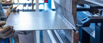
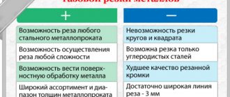
Types of gases for metal cutting
To begin with, let’s define that we call nitrogen and oxygen and air gas; air is also a gas.
When cutting with a laser (either CO2 or fiber), gas is supplied through the nozzle along with the laser in order to remove combustion products from the cutting zone or to help the laser process the material.
Nitrogen
If we are talking about nitrogen or oxygen, then there are many ways to store and supply gas to the machine, the most basic is a gas cylinder, we screw a reducer onto the cylinder to regulate the pressure and from the reducer we run a hose to the machine.
Air
A compressor is an AIR supply device. That is, only air. Air can be used to cut small thicknesses, on average up to 2-3mm. A filtration system is needed to ensure that the air that goes through the compressor to the machine is clean, without water or oil.
If the filtration system is bad, then small particles of water and oil fly out of the compressor along with the air, they settle on the protective glass of the laser head and the glass quickly fails. Also, the entire air path of the machine and head is polluted.
But that’s not all, in some machines air is also used to operate pneumatic systems, so it is worth distinguishing between the air supply to the cutting machine and for the operation of pneumatics.
Most often, the necessary cleaners are already installed inside the machine; nothing additional is needed.
Oxygen gas cutting methods.
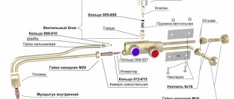
The separation cutting process begins with heating the part to be cut at the starting point of the cut with a heating flame 4 (Fig. 1) coming out of the heating nozzle 3, to the ignition temperature of the metal. Then cutting oxygen is launched through the channel of the cutting mouthpiece 2. The jet of cutting oxygen 5 comes into contact with the heated metal 1 and ignites it. During combustion, a significant amount of heat is released, which heats the underlying layers, and the combustion spreads throughout the entire thickness, burning a hole. If you move the cutter at the appropriate speed, the metal will be cut. The resulting slags 7 are blown out of the cutting cavity 6 by an oxygen stream.
Figure 1. Oxygen gas cutting: a - process diagram; b - universal cutter.
Manual oxy-fuel separation cutting is performed using a cutter. In Fig. 1, b shows a diagram of a universal injection cutter. This cutter is used for cutting steel with a thickness of 5 to 300 mm.
The cutter consists of a handle 7 with two nipples for hoses 5 and 6, a body 8, to which, using a union nut 11, a tip 13 is connected to a mixing chamber 12 and an injector 10. In the front part of the tip there is a cutter head 1, into which a tube is also soldered cutting oxygen 2. To supply gases to the cutter head there are valves 3, 4 and 9.
When cutting, you can use acetylene, coke oven gas, methane, hydrogen, lighting, petroleum, as well as liquid fuels - kerosene and gasoline.
The oxygen cutting mode is characterized by the power of the preheating flame, the pressure and consumption of cutting oxygen and the cutting speed, on which the quality and width of the cut depends. The duration of heating at the initial point of the cut with a preheating flame is determined by the thickness of the metal, its composition, flame power, type of fuel, etc.
The cutting speed is determined by the approximate formula
V = 40000/50 + δ ּ mm/min,
where δ is the thickness of the metal being cut in mm.
Cutting begins from the edge of the sheet. First, the heating flame is lit and then, when the metal is heated to white heat, cutting oxygen is released. If cutting begins in the middle of the sheet, then drill a hole in this place with a diameter equal to the width of the cut. The cutting speed is determined by the thickness of the sheet being cut, the flow rate and pressure of cutting oxygen. The distance from the cutter mouthpiece to the metal surface must always be maintained constant. When cutting steel 5–10 mm thick, the cutter is installed either vertically or at an angle of 5–10° to the metal surface in the direction opposite to the cutting direction. For thicknesses above 100 mm, the cutter is installed vertically in relation to the surface of the product.
When cutting metal with a thickness of more than 300 mm, the product should be heated in an oven to a temperature of 300 - 500 °. Cutting metal of large thicknesses is carried out with special cutters such as UBT-600 (thickness up to 600 mm) and R-100 (thickness up to 2000 mm). The latest cutter differs from the standard ones by the longer oxygen line and the presence of a so-called expanding nozzle. This nozzle promotes a higher gas flow rate than the nozzle of a conventional cutter. As a result, the oxides formed during cutting are blown out of the cut even at an oxygen pressure of 3-4 amu.
The main changes that occur in the metal in the cutting zone due to thermal and chemical influences include changes in structure and hardness. For medium-carbon steel (C content more than 0.3%, thickness 80 mm), the width of the heat-affected zone reaches 5 - 8 mm.
Batch cutting
Batch cutting is used for mass cutting of similar parts from sheets. The essence of the batch cutting process is that several sheets are folded together into a batch, tightly compressed with clamps and cut with an oxygen jet in one cutter pass. There are two methods of batch cutting: cutting with normal (high) pressure oxygen and cutting with low pressure oxygen.
With the first method, the thickness of individual sheets can be from 1.5-2 to 8-10 mm; the number of sheets in a package with a small steel thickness can reach 25-50. This requires that the sheets be well cleaned of scale and dirt and fit tightly together. A tight fit of the sheets is achieved by carefully straightening them and then compressing them with clamps.
The second method allows cutting even if there are gaps between the sheets of up to 3.5-4 mm or more; There is no need to compress the sheets.
. Cutting out parts according to the template.
When cutting with ordinary (high) pressure oxygen, the power of the preheating flame and the pressure of the cutting oxygen are set depending on the total thickness of the package. Due to the high power of the heating flame, severe overheating and warping of the top sheet are observed. It moves away from the underlying one and creates a gap, as a result of which cutting may stop. Therefore, pieces of waste sheets 6-8 mm thick are placed on top of the bag, which are clamped together with the bag. The cutting of the sheet package begins from the bottom edge. Then the cutter is gradually raised up the end of the bag to the top edge and then begins to be guided along the line of the intended cut. After cutting is completed, rapid cooling (for example, with water) is recommended to facilitate separation of the cut parts.
Mechanized cutting
For mechanized cutting, special machine cutters are produced. According to the principle of operation, they do not differ from manual ones. Their design allows for easy installation on gas cutting machines.
Mechanized oxy-fuel cutting of pipes.
The heating flame is controlled by an oxygen and gas valve. The metal is heated to a straw color, the cutting oxygen valve is opened and cutting is performed. If you need to extinguish the flame, first close the flammable gas valve, and then the oxygen valve. If the torch tip overheats, it is cooled with water, first closing the flammable gas valve, but leaving the oxygen valve open. If clogged, the mouthpiece is cleaned with a copper or aluminum needle.). Oxygen cutting machines are divided into stationary and portable. A portable machine is a self-propelled cart with electric, spring or pneumatic drive, on which an injection cutter and mechanisms for adjusting it to the cutting position are installed. The machine can be equipped with several cutters. It is installed on the workpiece to be cut (sheet, pipe, profile) and moves along it during the cutting process according to markings or a copier. Examples of portable machines: MPG-2 for cutting steel sheets 5...160 mm thick at a speed of 0.9...16 m/min, PGF-2-67 for cutting flanges and disks with a diameter of 50...450 mm from steel sheets 5...60 mm thick at a speed of 0.1...0.9 m/min. Stationary machines, depending on their design, are divided into portal (P), portal-cantilever (Pk) and hinged (W). Based on copying systems, there are machines with digital software (C), photocopying (F), magnetic (M) and linear (J1) - for straight cutting - control. According to the cutting method, the machines are designated: for oxygen (K), for plasma-arc (Pl) and gas-laser (GL) cutting. Oxygen cutting technology The parameters of the oxygen cutting mode include flame power, cutting oxygen pressure and cutting speed. The flame power is characterized by the consumption of combustible gas per unit time and depends on the thickness of the metal being cut. The power is chosen to ensure rapid heating of the metal at the beginning of cutting to the ignition temperature and the necessary heating during cutting. For manual cutting, the power required is 1.5…2 times more than for machine cutting. When cutting castings, it is increased by 3...4 times, since the surface of the castings is covered with sand and burnt marks. For cutting steel up to 300 mm thick, a normal flame is used, for larger thicknesses it is carburized with an excess of acetylene. The length of the torch of such a flame should be greater than the thickness of the metal being cut. The cutting oxygen pressure depends on the thickness of the metal, the shape of the cutting nozzle and the purity of the oxygen. With a thickness of 5...20 mm, the pressure can be 0.3...0.4 MPa, with 60...100 mm - 0.7...0.9 MPa. Excess pressure, as well as its lack, reduces cutting performance and deteriorates the quality of the cut surface. The cutting speed must correspond to the rate of metal oxidation along the thickness of the sheet being cut. At a slower speed, the upper edges of the sheet being cut will melt and a stream of sparks from the cut will flow out from the back side of the cut in the cutting direction. If the speed is too high, the spark beam will be weak and will deviate strongly in the direction opposite to the cutting direction. The cutting line will deviate from the vertical, lag behind, and the metal may not cut through. At normal speed, the flow of sparks should be calm and almost parallel to the stream of cutting oxygen, it only deviates slightly against the direction of cutting. Reducing oxygen purity by 1% reduces cutting speed by 20%. Therefore, it is necessary to use oxygen with a purity of at least 93.5% for cutting. When cutting, you need to maintain a constant distance between the mouthpiece and the surface of the metal being cut. It affects the quality of the cut and depends on the thickness of the metal: with a thickness of 3...10 mm, it is better to set this distance to 2...3 mm, with a thickness of 100...300 mm, 7...10 mm. Before cutting, you need to prepare the sheet to be cut. It must be laid on supports so that the gap between its bottom surface and the floor is at least 100 mm plus half the thickness of the metal being cut. Typically cutting is done in the down position. However, under installation conditions, the spatial position of the cut may be different; it has little effect on the quality of the cut. The surface of the sheet at the cut site must be cleaned. When cutting manually, a strip 30...50 mm wide is cleaned with a cutter flame. Before cutting on stationary machines, the sheets are first straightened on sheet-straightening rollers, and then the entire surface is cleaned chemically or mechanically (for example, shot blasted). The cutting process begins by heating the metal at the beginning of the cut to its ignition temperature in oxygen, then cutting oxygen is introduced and, making sure that oxidation of the metal has begun throughout its thickness, the cutter is moved along the cutting line.
21. Cutting thick metal is performed as follows. The cutter mouthpiece is first installed perpendicular to the surface of the metal being cut so that the jet of the heating flame, and then the cutting oxygen, is located along the vertical edge of the metal being cut. After heating the metal to the ignition temperature, a stream of cutting oxygen is released. The movement of the cutter along the cutting line begins after the metal is cut through its entire thickness at the beginning of this line. In order to prevent cutting lag in the lower layers of the metal, at the end of the process you should gradually slow down the speed of movement of the cutter and increase the tilt of the cutter mouthpiece to 10 ... 15° in the direction opposite to its movement. When cutting thick steel sheets, it is recommended to start process I from the bottom edge and apply preheating to 300 ... 400 ° C. In this case, cutting at an increased speed is possible. The speed of movement of the cutter must correspond to the speed of metal burning. If the speed of movement of the cutter is set correctly, then a stream of sparks and slag flies out of the cut straight down, and the edges are clean, without sagging or melting. At a high speed of movement of the cutter, the flow of sparks lags behind it, the metal at the lower edge does not have time to burn and the cutting process is disrupted. At a low speed, a sheaf of sparks is ahead of the cutter, the edges of the cut are melted and covered with smudges. The cutting oxygen pressure is set depending on the thickness of the metal being cut and the purity of the oxygen. The higher the purity of oxygen, the lower the pressure and oxygen consumption per 1 m of the section.
. The cutting process causes changes in the structure, chemical composition and mechanical properties of the metal. When cutting low-carbon steel, the thermal effect of the process on its structure is negligible. Along with areas of perlite, a nonequilibrium component of sorbitol appears, which even somewhat improves the mechanical properties of the metal. When cutting steel with a high carbon content, as well as alloying impurities, in addition to sorbitol, troostite and even martensite are formed. At the same time, the hardness and brittleness of the steel greatly increase and the machinability of cut edges deteriorates. Cold cracks may form. A change in the chemical composition of steel is manifested in the formation of a decarbonized layer of metal directly on the cutting surface, as a result of carbon burnout under the influence of a jet of cutting oxygen. Somewhat deeper than that of the parent metal, there is an area with a high carbon content. Then, as you move away from the section, the carbon content decreases to the initial value. Burnout of steel alloying elements also occurs. The mechanical properties of low-carbon steel remain almost unchanged during cutting. Steels with a high content of carbon, manganese, chromium and molybdenum are hardened, become harder and crack in the cutting zone. Stainless chromium and chromium-nickel steels, cast iron, non-ferrous metals and their alloys are not amenable to conventional oxy-fuel cutting, since they do not satisfy the above conditions.
Oxygen flux cutting
The essence of the oxygen-flux cutting process is that flux powder is introduced into the cutting zone, heated by a gas flame, along with a jet of cutting oxygen, which burns in oxygen, releasing heat that increases the temperature in the cutting zone - this is the thermal effect of the flux. The flux combustion products form liquid slags with the refractory oxides of the material being cut, which are removed from the cut by a stream of cutting oxygen - this is the chemical effect of the flux. And finally, the particles of flux powder do not burn immediately and, moving during the combustion process into the depth of the cut, by impact friction they erase refractory oxides from the surface of the edges, helping to remove them from the cut - this is the abrasive effect of the flux.
The increase in the amount of heat released during this process allows it to be used for cutting materials whose oxidation is associated with the formation of refractory and viscous compounds. The calculation of the flux composition for cutting specific metals is carried out using phase diagrams based on the conditions for obtaining a slag composition with a minimum melting point and viscosity.
Equipment for oxygen-flux cutting consists of a cutter, a flux feeder and a device for supplying flux to the cutter. Cutters for oxygen-flux cutting differ from cutters for oxygen cutting only in that the channels for supplying cutting oxygen are made with a larger diameter.
Three flux supply schemes are used: external, single-wire under high pressure and mechanical (Fig. 158). According to the first scheme, oxygen 2 is supplied to the upper and lower parts of the tank 1 with flux. In the upper part, pressure is created, and in the lower part, oxygen is blown into the hose 3, sucking (injecting) the flux. The gas-flux mixture is fed through a hose 3 into a head 5 placed on the cutter 4, coming out of the holes of which, it is sucked in by a stream of cutting oxygen and enters the cutting zone. With this scheme, any oxygen cutter can be used; you just need to put a head on it to supply flux. In a single-wire circuit, flux 3 is injected from the tank directly by a jet of cutting oxygen 6. The flux-oxygen mixture is supplied through a hose 3 through the central channel of the cutter 4. With mechanical supply, a screw 7 with an electromechanical drive 8 is installed in the lower part of the flux tank 1. When the screw 7 rotates, the flux is captured by it and is pushed through the hose 3 into the cutter head 4, where it is picked up by a stream of cutting oxygen 6.
Rice. 158. Flux supply schemes for oxygen-flux cutting:
a - external; b - single-wire under pressure; c - mechanical; 1 — tank with flux; 2 - oxygen; 3 - hose; 4 - cutter; 5 - head; 6 — jet of cutting oxygen; 7 - auger; 8 - electromechanical drive
The technique for oxy-flux cutting is basically the same as for oxy-fuel cutting. When using oxygen-flux cutting, the power of the preheating flame must be 15...20% greater so that the flux particles are evenly heated until ignited. The distance between the end of the mouthpiece and the surface of the sheet being cut is increased to 25 mm, and when cutting metal with a thickness of more than 100 mm - to 40...60 mm. This reduces the possibility of clogging the mouthpiece outlet channels. The cutting speed must be matched to the amount of flux supplied per unit time. The correct choice of flux consumption can be assessed by the presence of a small bead of molten iron on the upper edges of the cut. When the thickness of the metal being cut is 10...200 mm, the cutting speed is selected within the range of 0.76...0.23 m/min, and the flux consumption is 0.25...0.8 kg/h. The flux supply valve is opened after the heating flame is ignited. The duration of metal heating at the beginning of the process is much shorter than with oxygen cutting: for sheets with a thickness of 10...80 mm, heating requires from 15 to 120 s. The cutting oxygen pressure, for example, when cutting Kh18N10T steel with a thickness of 10...100 mm is 0.5...07 MPa.
Rice. 159. Scheme of cutting with an oxygen lance:
1 - steel pipe; 2 — handle; 3 - material to be cut; 4 - stand
Oxygen-flux cutting is used not only for metals, but also for cutting concrete and reinforced concrete. The difference is that since concrete does not burn in oxygen, when cutting, fluxes with greater thermal efficiency must be used than for metals. A good result is obtained by a flux consisting of 75...85% iron and 15...25% aluminum powders. Flux is supplied to the cutter via an external circuit using compressed air or nitrogen, blowing the gas-flux mixture into a stream of cutting oxygen. It is possible to cut concrete with a thickness of 90...300 mm at a speed of 0.15...0.04 m/min with a flux consumption of 20...42 kg/h. The process of cutting concrete with an oxygen lance is much more effective (Fig. 159). In this method, oxygen is blown through a steel pipe 1 (spear) with a diameter of 10...35 mm with a wall thickness of 5...7 mm and a length of 3...6 m. Steel rods are placed in large diameter pipes to increase their mass, small diameter pipes are wrapped with wire. The end of the pipe is heated by any heat source (for example, an electric arc or gas flame) to the ignition temperature in oxygen, then oxygen is supplied through handle 2 and the spear is pressed to the surface of the material being cut 3. As a result of the combustion of the end of the spear in oxygen, liquid iron oxides are formed, reacting with concrete and forming slags that are blown out of the cutting cavity. When cutting, the spear is periodically rotated and moved back and forth. The spear can be mounted on a rack 4, or in the hands of a worker. As the pipe burns, it is fed into the depth of the cut. In addition to oxygen, a gas-flux mixture can be supplied to pipe 1. This process is called powder lance cutting. Typically, a flux consisting of 85% iron and 15% aluminum powder is used. Spear cutting is used to remove profits from steel castings, to burn holes in thick metal before oxygen cutting, and to cut concrete and reinforced concrete up to 1200 mm thick.
When using oxygen-flux cutting, to prevent the flux from igniting in the cutter, hose or tank, you cannot use powders containing more than 96% pure iron or pure aluminum. When cutting copper, alloys with a high manganese content and when there is sand in the flux, you must use a respirator. When feeding flux through the cutting nozzle of the cutter, do not use fine, flammable iron powders. Regular checks of the cutter for proper operation are mandatory. When cutting with an oxygen or powder lance, the source of danger is an intense flow of hot slag particles scattered over a distance of several meters. This is a fire hazard and can cause burns to workers.
High-alloy steel, cast iron, copper and aluminum alloys, slagged metal, as well as non-metallic materials such as refractories and reinforced concrete are subjected to oxygen-flux cutting. The composition of fluxes for oxygen-flux cutting of materials is presented in Table 2.
Oxygen-flux cutting is widely used in heavy mechanical engineering and metallurgy for trimming casting profits, cutting blooms in a cold state, cutting pieces from hot ingots.
Table 2. Composition of fluxes for oxygen-flux cutting of materials
Spear cutting
The spear cutting method is used for cutting low-carbon and stainless steel and thick cast iron, as well as for cutting reinforced concrete.
The thickness of steel blanks cut with an oxygen lance can reach several meters.
There are two main methods of lance cutting: oxygen and oxygen-powder lance (oxygen-flux cutting).
Burning holes in a cut blank of steel or cast iron or in reinforced concrete is done with the end of a steel tube (spear), into which oxygen is continuously supplied under pressure. The heat necessary for the process is created by combustion of the end of the tube and the iron of the processed blank.
At the beginning of the process, the end of the tube is heated to ignition temperature by a torch or electric carbon arc. The oxygen pressure at the beginning of the process is 2-3 kgf/cm2, and when the working end of the spear goes deep into the metal to 30-50 mm, the oxygen pressure is increased to 8-15 kgf/cm2, depending on the thickness of the metal being burned.
To avoid welding the heated end of the spear to the wall of the hole, the spear periodically performs reciprocating movements within 100-150 mm, turning one turn in both directions. When burning holes in reinforced concrete, welding of the spear is excluded, so only rotational movements are made with it.
As a spear, a steel gas tube with a diameter of , with 3-4 pcs. low carbon wire with a diameter of 5 mm. These wires, when the end of the spear burns, increase the amount of heat generated at the cutting site. Oxygen is supplied to the lance tube from the cylinder ramp through a hose with an internal diameter of 13 mm, connected to the tube through a lance holder with a collet or bolt clamp.
When using powder-oxygen lance cutting, after heating its end and supplying oxygen, powdered flux begins to be fed into the lance tube, which burns upon exiting the tube, forming a flame 100-150 mm long with a temperature of about 3500-4000 ° C. When cutting and burning holes In this case, the end of the spear is kept at a distance of 30-100 mm from the wall (bottom) of the hole being burned. A mixture of 80% iron and 20% aluminum powder is used as a flux.
By moving the spear in a horizontal or vertical direction, using these methods you can not only burn holes, but also cut blanks, cut off castings, and cut holes in reinforced concrete, brick and stone building structures.
Oxygen spear cutting.
Oxygen lance cutting is effective for burning holes in concrete. With this method, oxygen is supplied through a steel pipe (lance), one end of which is heated to the melting temperature and pressed against the surface of the concrete. Oxygen, interacting with the hot end of the pipe (spear), is oxidized, forming liquid iron oxides. These oxides react with concrete and turn into slag, which is easily blown away. By pushing the spear forward, we achieve penetration deep into the concrete mass and, ultimately, burn a hole. It is good for these purposes to use a thick-walled seamless pipe with a diameter of 20-35 mm; a thin-walled gas pipe with a diameter of 10.2-21.3 mm, filled 60-65% with steel rods, or a thin-walled gas pipe of the same diameter, wrapped on the outside with steel wire with a diameter of 3-4 mm. Rods and wires play the same role in the cutting process as iron powder does in oxy-flux cutting. Heating of the pipe (spear) before cutting is usually done with a gas burner or carbon electrode.
In Fig. The simplest diagram of burning a hole with a spear is shown. This technology makes it possible to obtain holes with a depth of up to 4000 mm and diameters of up to 1200 mm. The same method can be successfully used when burning holes in a steel workpiece.
Rice. Burning concrete with an oxygen lance. 1 - concrete; 2 - spear; 3 — protective screen; 4 — handle for feeding and rotating the spear during operation; 5—oxygen supply; 6—air supply with flux
Powder-spear cutting.
Powder-spear cutting differs in that instead of wire (rods) iron powder is used, which contains 85% iron and 15% aluminum powders. This powder (like flux) is fed into the cutting area along with a stream of oxygen.
The recommended operating modes are as follows:
1. If you need to burn a hole with a diameter of 55 mm and a depth of 500 mm, you must provide an oxygen pressure of 0.7 MPa and have a supply of powder at a consumption rate of 30 kg per hour. In this case, the cutting speed can be in the range of 120-160 mm per minute, and the estimated consumption of the spear (pipe) will be 4 mm per 1 meter of hole length.
If the hole depth is greater (within 1500 mm), then the oxygen pressure should be 1.0-1.2 MPa, the flux consumption will not increase (30 kg per hour), the cutting speed will drop to 40-70 mm per minute, and the spear consumption will increase to 6 mm per 1 meter of hole length.
Plasma arc cutting
Plasma arc cutting is based on the ability of a compressed arc to penetrate deeply into the metal, melting it along the cut line with an arc discharge. Under the influence of the high temperature of the compressed arc, gas 2, passing through the arc discharge, strongly ionizes, a plasma jet is formed, which removes the molten metal from the cut site. Arc 1 is excited between the metal being cut 4 and a non-consumable tungsten electrode 5 located inside the cutter head 6. Arc gas-discharge plasma 3 is called low-temperature (its temperature is 5000–20,000°C).
The plasma-forming gases used in plasma-arc cutting must ensure the production of plasma and the necessary protection of the tungsten electrode from oxidation. Argon, nitrogen and mixtures of argon with nitrogen, hydrogen and air are used as such gases. Lanthanated tungsten VL-15 is used as electrodes. The tungsten electrode is placed with the plasmatron nozzle. The plasma jet has a high outflow velocity and the shape of an elongated cone, the cross-section of which at the exit corresponds to the cross-section of the nozzle. Plasma arc cutting is used to cut metals that are impossible or difficult to cut by other methods, for example, when cutting corrosion-resistant alloy steels, aluminum, magnesium, titanium, cast iron and copper. When cutting with a plasma jet, the metal being cut is not included in the electrical circuit of the arc. The arc burns between the end of the tungsten electrode and the inner wall of the water-cooled tip of the plasma torch. The essence of plasma arc cutting is to melt the metal with a plasma jet and blow out the molten metal from the cutting zone.
Scheme of the plasma cutting process: a - plasma arc, b - plasma jet
The figure schematically shows the plasma jet cutting process. Power is supplied from a direct current source 3. The minus is supplied to the tungsten electrode 4, and the plus is supplied to the copper nozzle 2, which is cooled by water. The arc 6 burns between the electrode and the nozzle and is blown out by a gas mixture from the internal cavity of the mouthpiece 5 to form a plasma jet that melts the metal 7 being cut. Argon and a mixture of argon and nitrogen are mainly used as plasma-forming gas. A plasma jet is used when cutting thin metal. The cutting speed of a plasma jet depends on the properties of the metal being cut and on the parameters of the cutting mode (current strength, voltage, gas flow). A plasma jet can be used to cut both manually and mechanizedly. For plasma arc cutting, special equipment is used that is powered by electrical energy. The main element in plasma cutting is a device for controlling the cutting operating cycle - supply and shut-off of gases, ignition of the pilot arc.
For manual plasma cutting, a RDM-2-66 plasma torch is used. The plasma torch consists of a head 4, a mouthpiece with a forming nozzle 3 and a handle 5. The cutter head has a water-cooled body, to which water is supplied and discharged through sleeves 8. The mouthpiece is isolated from the current-carrying body with a rubber gasket. The valve block, mounted on the handle, consists of a valve for supplying argon 10 with fitting 9, a lever valve 6, which allows cutting in a mixture of argon with hydrogen or nitrogen, and fitting 7. The cutter has a support roller 2 and a shield 1. In the cable The hose package includes two gas hoses - for argon and hydrogen or nitrogen and two water cooling hoses. In one of the cooling sleeves there is an operating current cable with a cross-section of 10 mm2, which is connected to the minus of the power source.
The RDM-2-66 plasma torch is designed for manual separation cutting of aluminum and its alloys up to 25 mm thick and stainless steels up to 20 mm thick.
Plasmatron RDM-2-66
The VNIIavtogenmash Institute, based on the RDM-2-66 hand-held plasma torch, created the water-cooled RDP-1 hand-held plasma torch and the air-cooled RDP-2 plasma torch.
The RDP plasma torch is shown in the figure. It consists of a head with a forming nozzle, a handle with a support roller and a shield, and a control unit, which is mounted on the inlet gas communication. Along the axis of the head there is a collet clamping device in which a tungsten electrode is secured. At the rear of the handle there is a button for remotely turning on and off the power source and a valve for supplying working gas is located.
RDP cutter from the set of universal KDP equipment
The power source is welding rectifiers of the VKS-500 type. The universal set of equipment KDP-1 with plasma torch RDP-1 is designed for the highest operating current of 400 A and is intended for cutting aluminum and its alloys up to 80 mm thick, stainless steel up to 60 mm thick and copper up to 40 mm thick. Argon and mixtures of argon with nitrogen or hydrogen are used as gases.
The set of universal equipment KPD-2 with plasma torch RDP-2 is designed for a maximum operating current of 200 A and is intended for cutting aluminum and its alloys up to 50 mm thick, stainless steel up to 40 mm thick and copper up to 25 mm thick. The RDP-2 cutter can be used at assembly and construction sites outdoors at any temperature.
Diagram of external connections of the KDP-1 kit
The installation diagram of KDP-1 for plasma-arc cutting is shown in the figure. It consists of cylinders), a current source 2, cooling water 3, a collector 4, a cable package 5 and a cutter 6. The efficiency installation works according to the following principle: set the operating pressure on the gas cylinders, open the water supply valve to cool the cutter and turn on the source switch nutrition. Open the gas valves on the plasmatron and by pressing the button on the handle close the electrical circuit with the electrode. Then, a lighter rod is inserted into the cutter nozzle, from which a stream of argon flows, and the gap between the electrode and the tip is closed. At the moment the rod is removed, an auxiliary arc occurs between the electrode and the nozzle tip, and a jet of arc plasma is blown out of the nozzle. The tip of the plasma torch is brought to the beginning of the cut, and at the moment of contact with metal 7 the cutting arc is excited. At the same time, by pressing the valve lever on the plasmatron, the supply of working gas is opened and the auxiliary gas channel is closed. To stop cutting, it is necessary to move the plasma torch head away from the surface of the metal being cut. The power source in all KDP installations is two VDG-501 rectifiers, which are connected in series, which provides an open circuit voltage of 180 V.
For semi-automatic plasma-arc cutting, semi-automatic machines of the PRP type are used. The installation consists of a PRP-1 plasma torch, a VDG-500 rectifier and a trolley. The semi-automatic plasma torch consists of a cylindrical body with a collet-mounted tungsten electrode. The internal nozzle is isolated from the cathode system and included in the pilot arc circuit. In parallel with this circuit, the discharge circuit of the high-frequency oscillator is connected. This allows you to press the start button not only to apply voltage, but also to initiate an arc between the cathode and the internal nozzle. Simultaneously with the initiation of the auxiliary arc, the engine of the mobile cart is turned on and the auxiliary arc is brought to the edge of the metal being cut; at the moment of contact with the metal, the main arc appears. Cutting is stopped by pressing the button.
For plasma-arc cutting of non-ferrous metals and alloys, as well as stainless steels, the URPD-67 installation is used. The installation operates on argon-hydrogen or nitrogen-hydrogen mixtures. Two PSO-500 welding converters are used as power sources, which are connected in series. The plasma torch for manual cutting is equipped with a trolley.
GOST 12221-79 establishes four types of equipment for plasma-arc cutting: Plr - for manual cutting, Plrm - for manual or machine cutting, Plm - for machine cutting, Plmt - for precision machine cutting. For machine cutting, devices of the types Plm-10/100, Plm-60/300, Plm-160/630, Plmt-50/300 are used.
Devices of the PLM-10/100 type are called devices for microplasma cutting. For this type of cutting, the AVPR-3 device, developed by the Institute of Electric Welding named after. E. O. Paton. The AVPR-3 device consists of a power supply and a microplasma torch VPRM-1. The torch can be installed on ASH, SGU machines, a welding tractor or a portable cart.
Devices of the PLM-60/300 type include the air plasma cutting installation UVPR "Kyiv". It consists of a power supply, a control cabinet and a VPR-9 cutting plasma torch with a bushed zirconium cathode. The plasma torch has a vortex arc stabilization system. Compressed air is used as a plasma-forming gas. The VPR-9 plasma torch can be installed on portal-console and portal cutting machines.
The power of the cutting arc in devices of the PLM-160/630 type reaches 180 kW. They consist of a power source, a control cabinet and a cutting plasma torch. Devices of this type include EDR-2, UPR-601 and OPR-6-2M units. Argon and a nitrogen-hydrogen mixture are used as plasma-forming gases. Cutting plasma torches are installed on large cutting machines or on heavy self-propelled trolleys of the PPL-1 type, the movement speed of which can be adjusted within the range of 50-10,000 mm/min.
Devices of the Plmt-50/300 type provide cutting of parts according to the first accuracy class. They are designed for work with a rigidly stabilized arc at high voltages. The cutting plasma torch CA-142 operates on a mixture of argon, hydrogen and nitrogen.
Of the foreign devices of this type, the RA-20-2 (GDR) device is widely used. It consists of a power source, an automation and control unit mounted in one housing, a circulation pump and cutting plasma torches. The device is equipped with a machine plasma torch RV-20-3 and a manual plasma torch RV-20-N. Argon-hydrogen and nitrogen-hydrogen mixtures and compressed air are used as plasma-forming gases. When switching the operation of the plasma torch from gases to compressed air, the sleeve cathode with a tungsten insert is replaced in the plasma torch with a cathode with a zirconium insert. The type and brand of plasma arc cutting machine must be selected based on their purpose and requirements for cut quality.
Oxygen or nitrogen for cutting metal?
Oxygen cutting is the cheapest. Nitrogen cutting is much more expensive, but when processing almost all metals except ferrous metals, we use nitrogen if we want to preserve the properties of the metal.
You CANNOT cut stainless steel with oxygen . If we cut it with oxygen, the material will essentially burn, because combustion is nothing more than oxidation at high temperature, and oxygen is a combustion catalyst. Thus, we make rust from stainless steel, oxidize it, that is, we simply remove all its stainless properties.
And nitrogen is a non-flammable gas, it is inert, nothing burns in it, it performs another function - it protects the metal from oxidation, cools it and removes combustion products from the cut zone.
Ferrous metals are usually cut with oxygen.
Chernukha can also be cut with nitrogen, but this will be too expensive and unprofitable, and since it does not have stainless properties, there is no point in preserving them.
One more nuance - we use nitrogen to cut everything except titanium , which during laser cutting reacts with nitrogen, crumbles, and loses its structure and properties. To cut titanium you need argon .
Conditions for gas cutting
- The melting point of the metal must be higher than its ignition temperature in oxygen. (For St.Z, the melting point is −1539°C, and the ignition temperature is 1100-1200°C.) Carbon significantly reduces the melting point. Therefore, it is impossible to cut high-carbon steels and cast irons with a conventional cutter.
- The melting point of the metal must be higher than the melting point of its oxides. Otherwise, the oxide film will prevent oxygen from accessing the metal and combustion (cutting) will not occur. (Chromium oxide has a melting point of 2270°C, and the melting point for St.Z is −1539°C).
- The oxides formed during cutting must be sufficiently fluid. If there is an excess of them, they stick to the edges of the cut, and it is very difficult to remove them (Oxides of silicon, chromium, etc. have a high viscosity). And you can spend a lot of time, with little success, on removing them.
- The metal must be a poor conductor of heat, otherwise the heat from the flame will not be enough to heat the edge before cutting begins.
Gas pressure when cutting metal with a laser
So, the machine has two auxiliary gas connection sockets - an unregulated path for nitrogen or air and an oxygen path with a pressure regulator.
The first goes directly to the working head: that is, just as you set the pressure on the cylinder on the reducer, that’s how it works.
And the second - the oxygen path requires very precise pressure regulation, which is why there is a special regulator made by the Japanese company SMC. It allows you to set precise cutting pressure parameters directly from the program.
When we cut a material, it must first be punched. At the moment of this breakdown, the pressure should be 0.15-0.2 MPa, and during the cutting process, 0.5-0.6 MPa is enough and the machine must regulate this discrepancy in pressure.
If you pierce a material with oxygen at the same pressure as you use to cut it, then splashes of molten metal will fly, because... oxygen, as we found out above, is a combustion catalyst. There are no such problems with nitrogen; you can set the conditional 2 MPa and punch and cut at the same pressure.
Gas pressure regulator in a metal cutter
Returning to the pressure regulator - you cannot apply more than 1 MPa to it; in the best case, it will simply release excess pressure and you will have an excess consumption of oxygen; in the worst case, it will simply fail.
For cutting with nitrogen, the normal pressure is 1.6-1.8 MPa, and with oxygen - 0.5-0.6 MPa, i.e. gas consumption is almost three times less.
However, despite the fact that oxyfuel cutting is cheap, it is complex and requires experience in setting parameters.
A slight deviation in pressure, the wrong nozzle diameter - and you will have a bad cut.
But if you know how to work with oxygen, it turns out more efficiently and cheaper than nitrogen or air.
Speaking of air: what's the catch here?
Cutter Inspection
Inspection of the cutter using the example of P1 “DONMET” 150P
Attention! If continuous popping or kickback occurs, quickly close the flammable gas valves, then the oxygen valves, and cool the cutter. After backlash occurs, clean and blow out the injector, mixing chamber and mouthpieces, tighten the mouthpieces and nuts, and check the cutter for leaks.
Prohibited!
- Continue work if a flashback occurs; if it is impossible to adjust the composition of the flame for flammable gas or identify malfunctions of equipment, instruments and protective equipment, or violations of the cylinder fastening.
- Keep the sleeves on your shoulders, legs, under your arms or wrapped around your waist while working.
- Move with the torch flame lit. Cut vessels that are under pressure or contain flammable or explosive substances.
- Leave the cutter with the flame lit when forced to stop work or remove the worker from the workplace.
Air for metal cutting
If you are going to cut in air, you need to take care of a good filtration system, the cost of which can sometimes reach the cost of the compressor itself.
People think that I’m now going to grab God by the balls, not pay for gas, pay once for a compressor and that’s it – cheap and cheerful. But actually no, air cutting also costs money.
Disadvantages of Using Air to Cut Metal
It’s just a one-time and large investment. And the compressor also needs to be serviced - the oil needs to be changed. And it happens that the filters also fail, it works fine for three months, then suddenly it starts spitting. Condensation is flying from the receiver, that's all. And if you once clogged the duct, then installed air with normal filters, it still won’t help, because you will have to clean the duct itself, blow it with alcohol.
When working with air, you need to very thoroughly clean and dry the air path, because any moisture and oil that flies from the compressor will settle on the protective glasses and you will have to change them several times an hour.
For normal cutting with air, a pressure of 1.6-1.8 MPa is needed, but in order to achieve such an output pressure after all dryers and filtration systems, there must be 20-25 atmospheres before the filters. And such a compressor already costs normal money. Therefore, the cost of a compressor with a good dryer system will be quite expensive.
Think, maybe it’s more profitable for you to take a gasifier with nitrogen and just fill it once a month?
Let's summarize by air
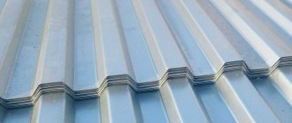
Air is only relevant if you are cutting no more than 1.5 mm and if you are not chasing the color of the edge.
If you cut stainless steel with air, the end will not be white, but will be slightly yellow, since air contains 8-10 percent oxygen.
Air is not free. It's difficult and expensive. For this whole system to work properly, it is worth investing well in it. If you are cutting chernukha, then stainless steel, then one, then the other, then it is better to work with gases.
Gas equipment and workplace equipment at a metal cutter
- Gas can be supplied in 40 or 70 liter cylinder This is not very convenient, since they have to be changed frequently and additional time is spent on this.
- There is a matrix of cylinders - 25 cylinders tied with hoses. The cylinder matrix lasts longer, but it takes up more space and is more difficult to refill and transport.
- Maybe a gasifier is a large cylinder that contains gas in liquid form. This is why the gas from the gasifier is very pure. Moreover, it is more economical.
You should not chase gas purity three nines (99.999%), four nines (99.9999%). Ninety-nine hundredths (99.99%) is already enough. The rest is redundant, it is not financially feasible and will cost a fortune. OCH (very pure) or OSCh (extra pure) is enough, test it and decide what suits you best.
In the next article we will talk about the control system, software and show you the coolest functions of a metal cutter that greatly simplify the work process.
Service and repair of a metal laser machine
Many people can sell metal cutters, but not everyone has the same experience and knowledge as our managers and service employees.
Perhaps this article contained many terms that were unclear to you, do not be alarmed, we will clearly tell you about all the nuances and teach you how to operate the machine correctly. Our training lasts three days, during which time you will learn everything you need about the structure of the machine and its maintenance, we will teach you how to select settings for different types of materials of different thicknesses and show you how to work with cutting modes that simplify your work and help save time and materials .
We have successful experience working with various industries and therefore can teach you a lot, share our experience and give you unique advice on how to optimally set up your production.