A broach is a tool with which metal is processed by broaching (one of the most common technological operations for metal cutting). This technology is used for parts used in many industries.
The working surface of the broaches can have a different profile depending on the purpose and type of tool
Vertical broach
The working principle of a vertical broaching machine for internal broaching is based on the fact that the main movement is performed rectilinearly in the vertical direction by the cutting element of the machine, while the workpiece of the future part remains stationary. In addition, when using the screw broaching method on such devices, which is one of the types of internal broaching, additional rotation is also given to both the workpiece itself and the cutting element.
Vertical broaching machine
A vertical internal broaching machine has virtually the same operating rules as a horizontal one, but with certain advantages, which include the following:
- during operation, machines of a similar class as such do not have the possibility of sagging and distortion of the axis of the broaching element;
- on a machine of a similar class it is not difficult to install additional broaches in the event of modernization;
- A vertical broaching machine occupies a relatively small area for operation. This is due to the fact that its entire operating cycle occurs strictly in the vertical direction.
- Machines with vertical broaching not only take up less usable space during operation, but are also much more convenient than their horizontal “colleagues”. Machines of this type are very often used in production, where global processing of light and medium-heavy parts is performed.
Scheme for setting up a vertical broaching machine
Vertical broaching machines also come in both external and internal broaching types. All such options are subject to the following criteria:
- traction force, it all depends on the machine model, can range from 50 to 200 kN;
- the maximum maximum amount by which the working carriage moves is in the range from 60 to 160 centimeters;
- the speed of the broach during the working cycle can vary from 0.5 to 14 meters per minute.
It must be said that both vertical and horizontal broaching machines use a semi-automatic operating principle in their process. As an exception, there can only be broaching machines with software, the entire manufacturing process of which is simplified as much as possible and has the highest speed.
An additional feature that distinguishes one from another machine for metal processing is the number of available working carriages, since there are machines not only with one, but also with several. The next characteristic feature is the position. The simplest is considered to be a single-position design, but the most effective are machines with a multi-position operating principle, since they contain factory table devices with a rotary system in their own technological equipment.
Horizontal broach
A horizontal broaching machine is used in all cases when there is a need to process the internal or external part of a part, the main movement of which will occur in the linear horizontal direction. Correct movement is achieved through special broaches having different profiles.
Horizontal broaching machine
The working cycle of such a machine is carried out only in a strictly horizontal direction. Removal of chips from the entire area of the workpiece during operation is carried out due to the uniform movement of the teeth over the entire length of the existing broach. In order for the entire process to be fully automated and safe, it makes sense to use a machine for processing and cutting metal with a CNC installed.
Machines with vertical broaching are designed for precision machining of the surfaces of parts of various shapes, made of both ferrous and non-ferrous metals. A vertical broaching machine is used, as a rule, in various industries - such as mechanical engineering - for the purpose of mass production of parts of all possible shapes.
Scheme for setting up a horizontal broaching machine
Overview of the machine model 7B55
The technical properties of broaching machines for working on metal include the following important criteria - the working traction force and the largest amount of broaching movement. Manufacturers from our country produce different models of broaching machines for metalworking that can satisfy all the necessary needs of the customer. One of these machines is model 7B55.
Appearance of broaching machine 7B55
The technical device of this machine has the following description:
- The main part of the technological equipment is considered to be a welded frame, hollow in the middle, in the middle of which a powerful hydraulic drive is located;
- the drive itself consists of a power cylinder and a rod, moving in a horizontal position along specialized guide slides;
- a cartridge is placed on the rod in which the broach is fixed;
- The machine diagram also has a specialized spare chuck, which is intended for attaching the end of the cutting tool.
During the work process, the additional cartridge moves along a horizontally placed slide at the same time as it is pulled all the way to the stop. At the end point of movement, their connection is broken using a specialized spring cam. After the cutting machine has completed the entire cutting operation, the broach returns to its first position and is again attached to the auxiliary chuck. Like most machines of this class, the 7B55 only supports semi-automatic processing of parts. However, the technical properties of broaching machines make it possible to carry out improvements by installing a CNC, which brings the entire work process to full automation.
Part processing technology
The description of the processing process on broaching machines is as follows: the part to be processed is fixed to a standard work table faceplate in compliance with all safety measures. A broaching device is passed through the hole of this part, which is fixed directly in the traction chuck. After turning on the start button, oil is supplied into the inside of the cylinder, which presses on the rod, forcing the broaching element to move.
At the time when the moving carriage with its thrust element runs into a special stop for rearrangement, the limit switch is triggered, as a result of which the working stroke of the carriage is stopped. At the next stage of operation, its movement in the opposite direction will occur.
At the final stage, the operator activates the feed idle button, after which it will return to its original position and at this point the working cycle of the device will be considered completed.
Modern horizontal broaching machine
The options for fixing the broaching element in the chuck also depend directly on the model of the broaching machine, which can be not only conventional and quick-release, but also fully automatic.
Due to the fact that there is a special thread on the shank of the machine body, the chuck is connected to the working carriage.
7B55 Horizontal broaching machine for internal broaching. Purpose and scope
The horizontal broaching machine 7B55 has been produced since 1981. The machine was discontinued and was replaced with a more advanced model. Currently, the plant produces more advanced horizontal broaching machines and semi-automatic machines: 7A523, 7A534, 7A545, 7555.
The horizontal broaching machine 7B55 is designed for processing, by broaching, pre-processed or rough through holes of various geometric shapes and sizes of parts made of ferrous and non-ferrous metals and alloys. Using special devices, you can process external surfaces.
The 7B55 broaching machine is distinguished by high productivity and high processing accuracy.
The most effective use of the 7B55 machine is in mass and large-scale production. The ease of readjustment of the machine allows it to be used in small-scale and individual production.
Design features of the horizontal broaching machine 7B55:
By agreement with the customer, the 7B55 machine is supplied both in a universal version and with special fixtures and tools for processing one or more specific parts.
When equipped with automated devices for feeding and removing workpieces, the 7B55 machine can operate in an automatic cycle, as well as be built into automatic lines.
The drive of the 7B55 machine is hydraulic, the speed control of the working and reverse strokes is stepless.
The removal and supply of the broach to the working chuck, as well as the cutting process, are mechanized.
For ease of maintenance, the machine is equipped with a mechanism for adjusting the stroke length of the working slide, centralized forced lubrication of the guides, signaling of dullness of the broach using an electric contact pressure gauge, and oil filtration in the hydraulic system.
Starting and safety electrical equipment is located in a separate electrical cabinet, which facilitates its maintenance and increases its service life.
The use of contactless track switches, low-current electrical control equipment and electrical control equipment and DC electromagnets ensures high reliability of electrical equipment.
The increased rigidity and vibration resistance of the machine design allows it to work in the entire range of operating speeds and traction forces, while maintaining a high class of surface cleanliness and broaching resistance.
- Hydraulic drive
- Stepless speed control of working and reverse strokes
- Mechanized feed in and out of the broach over the entire cutting length
- Centralized forced lubrication of rubbing surfaces
- Hydraulic oil filtration
- Signaling using an electric contact pressure gauge about the dullness of the cutting tool
- High reliability of electrical equipment due to the use of contactless track switches, low-current electrical control equipment and DC electromagnets
- Possibility of integrating the machine into an automatic line
On special order for an additional fee, the machine is equipped with a supporting prism, which allows you to compensate for the weight of the workpiece and simplify the process of its installation relative to the broaching axis, and a load lifter for installing and removing heavy workpieces and broaches.
At the request of the customer, the machine can be manufactured in one of two versions: with or without an attached bed (model 7B55U), and can also be supplied both in a universal version and with a special device and tool for processing one or more specific parts.
The machine is certified according to the first quality category.
Roughness of processed surfaces Rz20—Ra 0.63 μm (V5—V8).
Machine accuracy class N according to GOST 8-77.
The corrected sound power level LpA does not exceed 108 dBA.
Design organization - Minsk Special Design Moscow Bureau of Broaching Machines.
Main technical characteristics of the horizontal broaching machine 7B55
Design organization - Minsk Special Design Moscow Bureau of Broaching Machines.
Minsk Machine Tool Plant named after S.M. Kirov. Start of mass production in 1973.
- Nominal traction force – 98 kN (10,000 kgf)
- The longest working stroke of the slide is 1600 mm
- The diameter of the hole in the faceplate is 100 mm
- Working speed – 1.5÷11.5 m/min
- Main movement drive electric motor power – 17 kW
- Machine weight – 6.9 t
7B56 Location of components of a broaching machine
Photo of horizontal broaching machine 7B56
7B56 main components of a broaching machine
- electrical equipment
- slave cylinder
- work skids
- Remote Control
- cooling device
- support roller
- auxiliary cartridge
- auxiliary skid
- side stand
- locking and unlocking mechanism
- auxiliary cylinder
- working chuck
- work skids
- mechanism for regulating the movement of the machine
- coolant tank
- pumping unit
The main frame is used to accommodate the main parts of the machine: the working cylinder and the working slide, the alignment of which is ensured by bed strips welded inside the frame along its entire length. In the front part of the frame, the frame is closed by a massive base plate, in which a precise hole is made, strictly coaxial with the working cylinder of the machine. This hole is used to install the machine support plate. A slide is provided near the base plate, through which chips with coolant fall into a receiving box located next to the coolant tank. At the front of the main frame, there is a support roller mechanism at the bottom. Its purpose is to support the broach as its rear shank exits the auxiliary chuck. Support is provided until the end of the return stroke of the working slide, when the rear broach shank again enters the auxiliary chuck. The mechanism provides regulation using a spring device for working with broaches of different diameters.
The working slide connects the working cylinder rod with the working chuck. To install the working chuck, they are provided with an adapter sleeve with a conical mounting hole. The design of the working slide allows the load to be transferred directly from the hydraulic cylinder rod to the working chuck using a special coupling and coupler (Fig. 68). The working slides of manufactured horizontal broaching machines move along one flat and one V-shaped bed guide, which increases the geometric accuracy of the machine. The slides are equipped with screwed guide bars that allow compensation for wear in the guides. There is a follower at the bottom of the slide to lower the support roller in the main bed when the work slide approaches the base plate.
The mechanism for regulating the movement of the machine is mounted in the upper part of the main frame. It is made in the form of two rollers, the angular rotation of which turns on and off the limit switches that control the operation of the machine’s hydraulic system. These switches are located outside the main frame in a special housing. By adjusting the position of the cams attached to the rollers, the required values of the working and slow strokes are ensured, as well as the value of the slow stroke and the extreme position of the working slide at the end of the return stroke. The rotation of the cams occurs under the influence of a copier mounted on the working slide.
The attached frame is designed for mounting mechanisms that provide supply and removal of broach. The inlet and outlet movements are communicated simultaneously to the support roller 6 (see Fig. 67) and the auxiliary slide 8 from the auxiliary cylinder 11. At the end of the broach supply, when the support roller is lowered into the opening of the attached frame, the locking and unlocking mechanism 10 ensures the release of the auxiliary slide from the mechanism inlet and outlet. This allows the auxiliary slide to accompany the broach until the end of the cut, which becomes possible due to the fact that the support roller 6 is recessed. At the end of the return stroke, the auxiliary slides are again rigidly connected to the inlet and outlet mechanism using a locking and unlocking mechanism. After this, the withdrawal of the broach begins, at the beginning of which the supporting roller rises and becomes the support of the broach. Its rear shank is fixed in an auxiliary chuck.
When broaching with assisted broaching, the machine mod. 7B56 operates in full half-cycle mode. The interaction of the considered machine mechanisms is reflected in Table. 21. When working in a simple half-cycle mode, the mechanisms located in the attached frame are excluded from operation. The sequence of actions is completely preserved. The simple half-cycle mode is usually used when working with small broaches, for example, keyway ones.
The adjustment dimensions that determine the capabilities of the machine in terms of the broaching length and the length at which tool tracking is provided are shown in Fig. 68.
Rating of the best edge makers
Having studied the statistics, reviews and technical parameters of the most popular models of edge banding machines, a rating of the best was compiled:
| Manufacturer (model) | Specifications | Description and additions |
| Brandt models Ambition-1200, 1400, 1600 and 1800 | made in Germany, Ambition models - single-sided machines, designed to work with an edge of 0.4-2 mm for gluing it to workpieces of 8-50 mm, operating speed 6m/minute | created for processing (gluing edges) to straight end parts, the adhesive layer is applied evenly with special rollers and pressed tightly using rotating cylinders, the higher the serial model number, the higher the technical parameters of the machines become |
| Company KROM Russian manufacturer offering the best manual edge edging machines | model KROM-750 is a new product in the series of manual machines, ideal for private use and small businesses, works with PVC edges with a thickness of 0.3-3 mm at a working speed of 5 m/minute | The model is distinguished by high build quality and an affordable price, an order of magnitude lower than its foreign analogues, has a built-in reservoir for adhesive mass with a volume of 270 ml, and comes with a repair kit for quickly eliminating minor breakdowns |
| Felder Company The German company presents its customers with edging machines of various levels and classes. | universal (NEW-G320, G460, G330 and ForKa300-s-eco); professional (G500, NEW-G680, NEW-G670 and NEW-G660); Premium (perfect-710x-motion, perfect-608x-motion-plus, perfect-710e-motion, perfect-710x-motion-plus, NEW-perfect812e-motion and NEW-perfect812x-motion-plus); mobile (Felder-ForKa-200) | universal edgers are small in size and work with edges of 0.4-3 mm and workpieces of 10-45 mm; they are used for gluing edges to curved or straight workpieces; professional models are multifunctional edgers designed for rounding corners, jointing, polishing and scraping workpieces at a high level; they work with edge material of 0.4-3 mm and workpieces with a thickness of 8-60 mm; Premium-level machines - devices characterized by high productivity, the most accurate result of work and an almost invisible seam; Mobile edgers are flexible, small-sized, hand-held and very convenient tools, they are designed for additional, auxiliary work for furniture processing |
| Griggio Company Italian manufacturers offering machines of various levels: automatic and manual, designed for gluing straight edges made of laminate and natural wood | small-sized models are designed for facing an edge layer up to 3 mm thick and work with 45 mm workpieces, operating speed 1-4 m/minute | the GB-M model machine, weighing about 8.5 kg, is the smallest and easiest to operate; it has a variable temperature mode and speed adjustment; the rest of the presented models from this manufacturer differ in weight and dimensions, as well as stated power; these are highly professional devices for gluing edges of 0.4-8 mm on furniture pieces measuring 10-60 mm and operating speeds of 1-17 m/minute |
| company CEHISA Spanish manufacturers leading in the wood processing industry | Cehisa edge maker is one of the most popular, it is a one-sided, automatic machine for high-quality gluing of edges made of wood, veneer, laminate and melamine | machines from this manufacturer are in great demand and are actively used in large furniture production, as well as in low-power enterprises |
Hydraulic drive of broaching horizontal machine 7B510
Hydraulic diagram of the broaching horizontal machine 7B510
Hydraulic diagram
The basic hydraulic diagram of the machine is shown in Fig. 53. A high-pressure piston pump 30 type NP4M is shown conventionally in the figure. Pipeline 28 is connected to the suction cavity, and pipeline 29 is connected to the discharge cavity. The pump ensures the operation of the machine, carrying out the working and return strokes of the working slide using a hydraulic cylinder 19. The auxiliary hydraulic drive consists of a gear pump 1 built into the piston pump housing, and an auxiliary hydraulic cylinder 12 for supplying and removing the broach.
Oil from pump 1 is supplied to the support cylinder 31, to the central spool 33 and to the control mechanism, in which there are four pilot spools controlled by solenoids 24, 25, 26 and 27. The central spool 33, together with a disk 35 attached to its end, under by the action of the spring 34 is pressed to the left. The disk 35 has five holes for the passage of screws 37, which regulate the performance of the pump 30 (stator displacement). When pressure is applied under the piston 36, it will rest against the adjusting screw 37 with its rod and limit the advancement of the disk 35 with the central spool 33, which is connected to the piston 32 of the cylinder.
Let's consider the operation of the hydraulic circuit for a full cycle.
In the initial position, the working slide is in the extreme right position, the broach is in the retracted position. By pressing the “Start” button on the control panel, the pumps are turned on. In this case, all four electromagnets (24, 25, 26 and 27) are turned off, and the piston pump 30 does not pump oil, since the rotor and stator are concentric.
Broach supply
The broach is supplied by pressing the control button on the remote control. In this case, electromagnet 9 is turned on. Auxiliary spool 7 moves to the left and connects pipelines 3 and 8. Oil from gear pump 1 through pipeline 2, through a bore in the spool body, pipeline 3-8 enters under the right end of the main spool 4 and moves it to the far left position, connecting pipelines 2 and 6. Oil enters the rodless cavity of the auxiliary cylinder and moves the broach. At the end of the broach supply, the limit switch 13 is triggered, which turns off the electromagnet 9 and turns on the electromagnet 27. As a result, the oil goes under the piston 36 and shifts the pump stator to the left to the position adjusted by screw 37 (as shown in the diagram). At the same time, the left end of the broach with its shank enters the automatic cartridge mounted on the right end of the piston rod of working cylinder 19.
Slow working speed
As a result of the above movement, cavity I becomes discharge, cavity II becomes suction. Oil through pipeline 29 enters under the right end of the differential spool 23 and moves it to the left until it stops. Pipeline 29 communicates with pipeline 21, and oil enters the rod cavity of working cylinder 19 and moves it to the left until it stops. The oil displaced from the rodless cavity enters the suction cavity of the piston pump 30 through pipelines 20-28. Excess oil, caused by the difference in the areas of the rod and rodless cavities, is drained through spool 22, which maintains a constant pressure in the cavity of the working cylinder.
Fast working stroke
A fast working stroke is carried out when the cam is pressed on the limit switch 17. This turns on the electromagnet 25. The stator of the pump 32 further shifts to the left, increasing the productivity of the pump and the speed of movement of the working slide. At the end of the working stroke, when the first calibrating teeth of the broach enter the workpiece, the cam presses the limit switch 16, which turns off the electromagnet 25. A slow working stroke begins as a result of a decrease in pump performance, as the eccentricity of the pump block decreases. At the end of the working stroke, the limit switch 15 is activated and turns off the electromagnet 27 - a stop occurs.
Reverse
The reverse stroke occurs when electromagnet 26 is turned on. The piston pump block moves to the left, line 28 becomes discharge, and line 29 becomes suction. Oil through pipeline 28 enters under the left end of the differential spool 23 and moves it to the extreme right position. Pipeline 28 is connected to pipelines 20-21 and both cavities of the working cylinder 19 communicate in this way with the pump discharge line. Due to the unequal areas under pressure, the piston moves to the right. With further movement of the working slide, the cam presses the limit switch 17, which turns on the electromagnet 24. At the same time, slow motion begins due to a decrease in pump performance. At the end of the return stroke, the travel switch 18 is triggered, turning off the electromagnets 26 and 24. The slide stops, the left end of the broach is automatically released and the right end is clamped in the chuck 4 (see Fig. 52), located near the housing 5.
Broach outlet
The broach is retracted at the end of the slow return stroke. By pressing the cam on the limit switch 18, the electromagnet 10 is turned on. The spool, controlled by this magnet, takes the right position and connects pipelines 3 and 5. Oil from gear pump 1 through pipeline 2 through the bore in the spool body, pipelines 3 and 5 enters the left end of spool 4 and moves it to the extreme right position, connecting pipelines 2 and P. Through these pipelines, oil enters the rod cavity of the auxiliary cylinder 12 and moves the broach. At the end of the broach retraction, the limit switch 14 is triggered, which turns off the electromagnet 10. The auxiliary chuck slide stops. After installing the next part for processing, the cycle is repeated.
A simple cycle differs from the one described in that the mechanism for supplying and removing the broach is not involved in the operation.
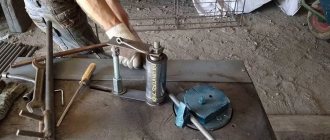
Characteristics of thread cutting equipment
In order for the unit to operate with minimal losses and develop high performance, the following indicators play a role:
- The power of the machine for production purposes should be up to 2.2 kW; such units are used in the continuous production of large quantities of goods. For the artisanal production of small batches of pipes, machines with a minimum power rating of 750 W are used.
- The spindle speed is an indicator that comes from the power indicator, and the speed of work depends on it. The range of indicators ranges from 28 to 520 rotations per minute. Professional equipment has at least three speeds that can be switched if necessary. For small workshops, low-power machines with a spindle speed of 28 revolutions per minute are purchased.
- The range of sizes of parts that the unit works with and the range of possible thread lengths. This parameter determines the type of workpiece; for example, for cutting with bolts, a size of 3−16 mm or 8−24 mm is suitable. Industrial processing of large-diameter pipes has other characteristics.
- The weight of the machine determines whether the unit is portable or stationary. The minimum weight of the thread coating device is 50 kg, it is easy to carry or transport.
Extra options
The designers have included convenient additional functions in each machine; depending on them, thread-cutting equipment is divided into types:
- Simple devices designed only for the threading operation; the rest of the work (moving pipes, installing stops, fixing, etc.) is performed by the worker. These machines are placed by a master in a small room for one-time auto repair work and various plumbing work.
- Automatic equipment allows you to reduce the work to installing the workpiece and turning on the start button. Such units combine the main function with additional drilling of holes, which can have a diameter range from 2.5 to 30 mm.
The operating tool can be located vertically or horizontally in the machine. In the first case, which occurs most often, cutting occurs using a tap. The horizontal arrangement of the cutting tool is used to create a threaded connection on gas and water pipes.
For external threads, dies, screw heads, and thread cutters are used. Internal threads are cut using taps and specialized cutters. Large manufacturing shops use vortex heads to create parts in the form of disposable and reusable screws. Using modern equipment, the following types of threads are created:
- metric or inch on pipes;
- conical and cylindrical;
- trapezoidal.
With the help of additional devices, several types of cutting are specified, different shapes are varied, and the pitch and inclination of the threaded turns are selected. For this purpose, the machines provide the possibility of changing the working executive tool. Some units have self-centering cutters with sharpened rollers for cutting pipes to the required size. For their manufacture, specially hardened high-strength steel is used for long-term operation.
General classification
The classification of metal-cutting machines is carried out according to various factors. These are divisions by weight, dimensions, type, accuracy class, degree of automation, and versatility. We need to talk about each of their groups in more detail.
Classification by type
There are 9 types of installations based on the type of equipment:
- Lathes. They occupy approximately 30% of the total mass of metal-cutting devices. The workpiece is clamped in a special clamp. The cutting process begins after installing the cutters, which remove a layer of metal under the influence of rotation.
- Boring, drilling units. They occupy 20% of the total mass of machines. The parts are fixed on the work table. Cutting occurs due to the rotation of the spindle with a drill clamped in the chuck.
- Grinding, grinding, polishing machines. They occupy 20% of the total mass of metal cutting installations. Metal cutting occurs due to the rotation of the abrasive material, which comes into contact with the working surface. The processing speed depends on the size of the abrasive.
- Devices for physical and chemical cutting of workpieces. Least common equipment.
- Devices for processing threads and teeth. Occupies 6% of the mass. Used for threading, manufacturing, and sharpening gears.
- Slotting, broaching, planing machines. They occupy 4% of the mass of metal-cutting equipment.
- Milling machines. They occupy 15% of the total mass. Processing of metal workpieces occurs due to the rotation of cutters of different shapes.
- Split installations. Used to separate reinforcement, profiles, corners.
- Machines for performing various operations related to cutting.
Classification by versatility
A separate division of metal-cutting machines is based on their versatility. There are two groups:
- Narrow profile installations. Used to perform one specific technological operation.
- Universal units. They are large-sized structures that are designed to perform various technological operations.
Classification by degree of accuracy
In terms of accuracy, metal-cutting machines come in several types, each of which has its own marking:
- Increased - denoted by the letter P.
- Normal - designation N.
- High - indicated by the letter B.
- Particularly high - designation A.
- The highest accuracy is indicated by the letter C.
To use units marked B, A, C, you need to prepare the room in advance. It must maintain a constant temperature and humidity level.
Classification by degree of automation
Based on the degree of automation, the following types of metal-cutting machines are distinguished:
- Manual models. The worker needs to clean, prepare workpieces, set up all moving elements independently, and coordinate the work process.
- Semi-automatic machines. The worker needs to change parts independently, turn on and off moving mechanisms.
- Automatic machines are units that process workpieces independently. Used in mass production.
- CNC equipment. The operator sets the required algorithm through the program. The moving mechanisms work independently, select optimal modes, load and unload parts.
CNC machines are gradually replacing other machines due to high processing accuracy and increased productivity.
Metal cutting automatic machine
Classification by weight
Industrial metal-cutting machines are divided by weight. Highlight:
- Lightweight - structures weigh up to 1000 kg.
- Medium - weight starts from 1 ton and ends at 10 tons.
- Large - weight from 16 to 30 tons.
- Heavy - weight from 30 to 100 tons.
- Super heavy - structures weigh more than 100 tons.
Designations are indicated in the technical data sheet.
Design and principle of operation of a broaching machine
Machines are classified according to two main criteria: by the shape of the structure (vertical and horizontal) and by the form of metal processing (external and internal broaching, as well as machines that process metal using both of these methods).
Horizontal broaching machine
The carriage guide, using a hydraulic drive, moves the slider, which ends with a device that secures the broach. If a long broach is used, its end is supported by a movable rest. The workpiece is installed in the center of the structure and moves through a broach along the slide.
Vertical broaching machine
The slider carrying the broach moves along the vertical guide of the carriage. Rotation is carried out using two headstocks (the first rotates, the second supports rotation). During the processing of the workpiece, the broach moves towards the rotating shaft.
A broach is a long, thin, rectangular tool with many blades. By crashing into the metal, it creates holes of the desired shape in the metal structure.
Optional equipment
The design of the machine may require the use of additional equipment: machine vices, clamping bars. A transverse key is often used with a flat broach lock; a bracket and a wedge are used for a cylindrical lock. Modern broaching machines involve the use of electronic equipment to control the production process, but this equipment is included in the design of the machine.
A used broaching machine can cost from RUB 2,500,000. For more complex designs the price increases. The maximum price of a broaching machine is 10,000,000 rubles.
Great Encyclopedia of Oil and Gas
| Multi-cutter attachment for a planer. |
Vertical-broaching machines, compared to horizontal-broaching machines, occupy a smaller area, are more convenient in securing broaches, but have a high workplace due to the need to place the broach under the working position. Vertical machines are used in mass production for processing light and medium-weight parts. The machines are produced for external and internal broaching. Their nominal traction force is 50 - 200 kN, working speed is 0 5 - 14 m / min, carriage stroke length is 600 - 1600 mm.
Vertical broaching machines occupy a significantly smaller area than horizontal ones. It is more convenient to install workpieces for processing on these machines; removal of the part can occur automatically; After broaching, there is no need to return the broach to its original position, since it is automatically secured either to the upper end or to the lower end.
| Horizontal broaching machine model 7510M. |
Vertical broaching machines are used mainly for external broaching.
| General view of a horizontal broaching mill. |
Vertical broaching machines are used mainly for external broaching. The operating principle of such machines is similar to horizontal broaching machines. To increase labor productivity in mass production, continuous broaching machines are widely used.
Vertical broaching machines for external broaching allow the following traction forces: mod.
Vertical broaching machines for internal broaching must be equipped with a guard that protects workers from injury if the broach falls out of the return mechanism chuck. The design of the fence must prevent hands from entering the area between the broach and the fence.
Vertical broaching machines for internal broaching must have a guard to protect workers from injury if the broach falls out of the return mechanism chuck.
According to the hydraulic drive scheme, vertical broaching machines differ little from horizontal broaching machines and have similar control units. All hydraulic drive calculations for reciprocating motion given in the planing machines section are generally applicable to broaching machines.
Machines used for broaching are divided into horizontal, vertical and continuous. Vertical broaching machines occupy a significantly smaller area than horizontal ones. It is more convenient to install workpieces for processing on these machines; removal of the workpiece can occur automatically; After broaching, there is no need to return the broach to its original position, since it is automatically secured either to the upper end or to the lower end. Vertical broaching machines are produced in one- and two-position versions; they can broach one or two workpieces at the same time.
When performing a broaching operation, the cutting speed is regulated by the kinematics of the broaching machines and the drive power of the broaching machines. Small vertical broaching machines have a tractive force of up to 100 kN and can reach cutting speeds of up to 25 m/min. In practice, the maximum service life of broaches is usually achieved at a cutting speed v 5 m/min. However, in order to increase productivity, the cutting speed can be increased to 10 m/min.
When performing a broaching operation, the cutting speed is regulated by the kinematic capabilities and drive power of broaching machines. Small vertical broaching machines have a tractive force of up to 100 kN and can reach cutting speeds of up to 25 m/min. In practice, the maximum service life of broaches is usually achieved at a cutting speed v 5 m/min. However, in order to increase productivity, the cutting speed can be increased to 10 m/min.
Pages: 1 2
Safety requirements
When working on broaching machines, it is necessary to strictly observe personal safety measures, which have general principles for all metalworking equipment.
There is a specialized document containing a set of conditions and requirements for broaching machines installed in production. So, for example, safety when cutting on metalworking machines with vertical broaching is ensured by installing a special protective element that protects the operator from injury in cases where the heavy broaching mechanism falls out of the chuck.
During the period of work on horizontal broaching machines, it is mandatory to install a protective folding screen with glass to monitor the process throughout the entire exit area of the broaching element.
It is worth noting that for safety reasons, it is strictly forbidden to install or remove the broach while the metalworking machine is operating. In the case of using a broach whose weight is more than eight kilograms, the use of a special lift is a mandatory requirement.
Features of operation
Operating personnel are required to place the workpiece in the working niche of the equipment. Next, after launch, the actual processing process begins. A key feature of the functioning of such machines is the fact that the working elements in the form of broaches do not remove chips immediately after cutting, but push them out only after the final exit from the body of the workpiece. Therefore, the range of operator tasks is also expanded due to the need to monitor how correctly machining is performed. On vertical-type broaching machines, the risks of deviations and incorrect cut lines are not so high, since bending of a long workpiece due to its own weight is eliminated.
Specifications
One of the disadvantages of such machines is the dimensions. As a rule, this is an elongated platform in which the workpiece is placed. Dimensional characteristics on average are about 2 m in length, 0.5 m in width and 1.5 m in height. However, the configurations can be different - accordingly, the sizes also differ. The weight is about 500 kg, so before installation it would be a good idea to provide a reliable foundation. From a productivity point of view, the speed of drawing, that is, processing, is also important. For example, a broaching machine from the Flexible Connections enterprise in modification SGP.12.35 provides a working speed of 220 mm/min. In other words, in one minute the equipment can make a cut on an internal surface more than 20 cm long. Here it is also worth considering the maximum processing area, since in most cases, performing the same cutting lines in two approaches is technologically unacceptable. The average length of a single service varies from 4 to 5 m.
Longitudinal planing and slotting machines
Universal two-column longitudinal planing machine mod. 7212 is designed for finishing surfaces and cutting long grooves of various profiles.
Technical specifications. The largest transverse dimensions: width - 1250 mm; height - 1120 mm; dimensions of the working surface of the table - 1120... 4000 mm; caliper feed: when moving along the crossbar - 0.5...25; for other movements - 0.25...12.5 mm/d. move. The main unit of the machine is the table on which the workpiece is fixed. The table moves back and forth relative to the fixed cutters installed in the supports. The table movement is the main cutting movement; the reverse motion of the table is auxiliary, carried out at high speed, and during the reverse motion the cutters rise. The supporting system of the machine consists of a bed, a stand and a connecting beam at the top.
Two calipers on the crossbar and one caliper on the stand make vertical and horizontal movements and are used for installation or are used for periodic feeding of cutters, as well as their deepening. The caliper can be rotated at an angle of 60°. A table drive is mounted next to the frame.
The main movement is the cutting movement, i.e. the movement of the table with the workpiece being processed is communicated from the M1 DC motor through a two-stage gearbox with an M1 gear coupling and a helical rack and pinion gear (Fig. 2). Maximum table movement speed vmax = (17/63) (26/49) 3.14 12 10 = 80 m/min. Technical characteristics of slotting machines are given in table. 2.
Table 2. Slotting machines
| Model | Stroke of the cutter, mm | Table movement, mm | Rotary table diameter, mm | Dimensions (L W H), mm | Weight, kg |
| GD 200 | 120…200 | 500 400 | 500 | 1900x1270x2175 | 2100 |
| GD 320 | 120…320 | 650 510 | 770 | 2850x2160x3010 | 5660 |
| GD 500 | 120…500 | 800 650 | 940 | 3440x2760x3465 | 8160 |
Rice. 2. Kinematic diagram of a two-column longitudinal planing machine: a - crossbar clamping mechanism; b - table; c — control panel
Information about the manufacturer of the broaching machine 7B510
The developer and manufacturer of the horizontal broaching machine 7B510 is the Minsk Machine Tool Plant named after S.M. Kirov , founded in 1881.
Machine tools produced by the Minsk Machine Tool Plant named after S.M. Kirov
- 7A510
- horizontal broaching machine for internal broaching, 100 kN - 7B510
- horizontal broaching machine for internal broaching, 100 kN - 7A534
- horizontal broaching machine for internal broaching, 250 kN - 7B55
- horizontal broaching machine for internal broaching, 100 kN - 7B56
- horizontal broaching machine for internal broaching, 200 kN - 8В66
- automatic circular saw cutting machine, Ø 280 - 8В66А
- automatic circular saw cutting machine, Ø 280 - 8G662
- automatic circular saw cutting machine, Ø 280 - 8G663
- automatic circular saw cutting machine, Ø 285 - 7523
— horizontal broaching machine for internal broaching, 100 kN - 7534
— horizontal broaching machine for internal broaching, 250 kN - MP8-876
– combined household woodworking machine - MP8-1540
– combined household woodworking machine
Why is stretching necessary?
A technological operation such as broaching is considered one of the most effective methods of metal cutting. To carry it out, you need a broaching machine and a special tool, the use of which gives a surface with a roughness of the order of 0.32 microns and an accuracy of geometric parameters corresponding to grade 6.
The tool used to perform broaching metal cutting consists of many teeth. Each is taller than the other when measured in a plane perpendicular to the direction in which the main cutting motion is carried out. Equipping the broach with many cutting blades and placing them in a certain position allows you to use only one such tool in order to remove the entire required volume of chips both during roughing of the surface and during its calibration.
Most broaching machines are set up for processing similar parts
Using broaching machines, as well as specialized tools, it is possible to process both external and internal surfaces of products of various configurations. When broaching, no feed movement is used: all processing is carried out by the main movement of the broach, which can be rotational or translational. The hole punching tool works on a similar principle. Despite the similarity of these technological operations, the fundamental difference between them is that the broaching tool works in compression, while broaching works in tension.
The video below shows the process of processing the inner surface of a pipe using the pulling method.
Broaching, when compared with other methods of metal cutting, has a whole list of advantages, which include:
- the possibility of reducing the cost of operating the equipment used;
- high wear resistance of the broach;
- high rate of minute feed due to the fact that processing is performed by several cutting teeth at once;
- the ability to work on broaching machines even for specialists with a low level of professional training;
- removal of stock from the surface at a high relative speed (this means high processing productivity);
- the ability to eliminate any types of defects in the treated surface;
- high precision processing of metal products.
Schemes of various types of broaching holes and surfaces
The tools that broaching machines are equipped with are made mainly from high-speed steels with a medium alloy level, which are quite expensive. For this reason, its use is recommended for industries that produce their products in large and mass batches.
Meanwhile, broaching machines and broaching can be used for small-scale and single-piece production of metal products, if their geometric parameters are standardized. One cannot do without such a technological operation even in cases where it is the only possible or most profitable method of processing.
Types and design of broaches
Broaches are classified according to a number of parameters. The following types of broaches are distinguished:
- with a cutting part made of high-speed, tool steel or hard alloy;
- solid or prefabricated - depending on the design;
- single- or multi-pass - depending on how many broaches are contained in one working set;
- working using a stepwise, profile or progressive method - depending on how the allowance is removed from the surface of the part;
- with straight and inclined or helical and ring arrangement of cutting blades on the working part.
Significant elements of a round broach
Various types of broaches are also distinguished according to their main purpose, and this classification can be called one of the most important. So, depending on this parameter, broaches for external and internal surfaces are distinguished. Using a tool designed for external work, it is possible to process surfaces of various configurations (gears, herringbone profiles, grooves, including T-type, cylindrical shafts, grooves of various shapes, including dovetail, splined shafts, etc.).
Broaching can process surfaces of various profiles
Hole broaching is a more common process operation than external surface broaching. Using a broaching machine and a broach, the following types of internal surfaces can be machined:
- keyways;
- screw type grooves;
- round holes (broaches for round holes);
- holes with different numbers of edges (faceted broaches);
- holes with slots (slotted broaches).
Slotted broach for machining holes
Despite the fact that different types of broaches are used to process internal surfaces, the design of these tools is almost identical and includes several components.
Front
This is the guide element. Before processing, the part is fixed precisely on the front part of the tool, which then smoothly transfers the processed surface to the cutting edges of the broach. The nominal cross-section of the front part of the tool and the size of the hole being machined must match, and the choice of the degree of fit is carried out taking into account the required gap between the broach and the walls of the hole.
Shank
Using this element, the broach is fixed in the chuck of the equipment used. For broaches of both round and flat types, the dimensions of the shanks are strictly specified by the provisions of the relevant regulatory documents (GOSTs 4043-70 and 4044-70).
Standard shank of a splined broach
Cutting part
This broach element consists of many teeth and is responsible for removing the required allowance from the machined surface. The geometric parameters of the cutting teeth of the broach, starting from its front part and ending with the rear, gradually change. Thus, the front tooth has the shape and dimensions of the hole that is to be processed, and the rear cutting element has geometric parameters corresponding to the characteristics of the finished hole. Due to the fact that the height of the broach teeth gradually increases towards its rear, there is no feed movement during processing, and the allowance is effectively removed from the surface being processed.
Main elements of the cutting part of a keyed broach
Support pin
This element is equipped with long and heavy broaches in order to ensure their support with the help of a steady rest.
Rear guide part
This part of the broach is necessary so that the workpiece does not become warped when the last cutting tooth leaves its hole.
Calibration part
This element is characterized by fewer teeth than the cutting part of the broach. The shape and dimensions of the teeth located on the calibrating part are completely identical to those of the finished hole.
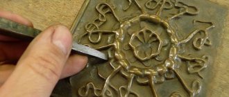
In order to identify errors, the parameters of the broaches are periodically monitored. The photo shows checking the front and rear angles of the keyway broach
Where is the machine used?
The very specificity of broaching processing determines non-standard requirements for the result obtained. Accordingly, the areas of use of finished products are not the most common. For example, they are used in the manufacture and modification of firearms. For such operations, planing and broaching machines are used, with the help of which the barrels of machine guns and pistols are produced. This machine is also used in the production of complex external finishing profiles, in cutting keyways and splines, as well as in calibrating multi-faceted and cylindrical holes. A common feature of all types of broaching machining is the wide possibilities of working with figured cuts, and in difficult conditions. In addition, the machine can be used for both non-metallic and solid materials. The fact is that the ability to process atypical workpieces with increased properties of rigidity and hardness is determined by elements of mechanical action, that is, broaches. And they themselves may have different characteristics.
Types of spline broaches and areas of their application
Splined broach, as mentioned above, is used for processing internal surfaces on which there are splined elements. Such tools, depending on the number and type of cutters with which they are equipped, can be:
- involute;
- sharp-slotted;
- 6-spline;
- 8-spline;
- 10-spline.
The broach for slotted holes TsL-2408-4333-8Х42Х46 is made of R6M5 steel
Splined broaching, depending on its type, can be produced according to one of the following regulatory documents:
- with an involute type profile: 50038-92 – two-pass combined; 50035-92, 28050-89 – conventional combined type; 25158-82, 25159-82 – for processing holes with a cross-section of 15–90 mm; 25157-82 – for processing holes with a cross-section of 12–14 mm; 25160-82 – for processing holes with a cross-section of 45–90 mm;
- with a straight-sided profile: 25971-83, 25972-83 – for processing eight-spline holes; 25969-83, 25970-83 – for processing six-spline holes; 24822-81, 24823-81 – for ten-spline holes;
- with screw-on shank: P 50035-92, 50036-92, 50037-92, 28048-89, 28049-89, etc.
In some cases, when it is not possible to select a standard tool, the manufacture of broaches can be carried out according to specially developed design documentation.
Using spline-type broaches, you can effectively perform the following technological operations:
- cutting keyways and splines;
- processing of rifled weapon barrels;
- calibration of internal holes of various types;
- production of aircraft engine turbine elements;
- stretching external surfaces with complex configurations.
Scheme of lingering operation
Scheme of broaching operation of a horizontal machine
Scheme of broaching operation of a horizontal machine
Scheme of broaching operation of a horizontal machine
The broaching movement is carried out using a hydraulic drive with two pumps. One of them, with a capacity of 200 l/min, serves to supply oil to the main (working) hydraulic cylinder, the other, with a capacity of 25 l/min, supplies oil to the auxiliary hydraulic cylinder. The hydraulic drive allows three cycles of operation: a full cycle, a simple cycle and an adjustment cycle. Full cycle work is carried out using long broaches (1200-1300 mm) with a rear shank. The broach is installed with the shank into the auxiliary chuck, which receives movement from the rod of the auxiliary cylinder. The broach moves, supported by a roller, to the working chuck. The chuck grabs the front shank of the broach and moves it along with the auxiliary chuck until it opens from the copier, carries out the working and return strokes, after which the auxiliary chuck grabs the rear shank of the broach and moves it to its original position.
A simple cycle is used when using short broaches. In this case, the broach is secured manually in a chuck mounted on a slide that receives horizontal movement from the main hydraulic cylinder along the frame guides. The auxiliary slide does not move during this cycle.
The setup mode is used when setting up the machine. This mode includes the tool movements necessary to prepare the broaching process.
The machine operates as a semi-automatic machine, but when equipped with automated devices for feeding and removing parts, it can operate in an automatic cycle and can be built into automatic lines. The machine is used in large-scale and mass production, and taking into account simple readjustment, it can be used in single and small-scale production.
One of the drawing schemes is shown in Fig. 50. The broach shank 5 is passed through the hole of the workpiece 7 and the sleeve 8 of the device 6 installed in the support plate 9.
The left end of the broach is fixed in an automatic chuck, consisting of a housing 4, a special sleeve 10 with an internal diameter corresponding to the broach, and two crackers 3. In the position shown, spring 2, pushing apart part 1 connected to the rod of the power cylinder, and the housing 4, moves the crackers 3, as a result of which the latter capture the broach shank.
When the broach moves to the left, the hole is machined. During idling, the broach returns to its original position.
Housing 4, approaching device 6, rests against it and stops.
The piston rod and coupling 1, continuing to move and compressing the spring 2, move the sleeve 10 to the right, the crackers 3 fall into the groove a, and the movement stops. Now the broach shank can be freely pulled out of the hole in sleeve 10, inserted into the next part and, having installed it again, begin processing.
The machine operates with a full and simple cycle. With a full forward stroke cycle, the broach is supplied, the working stroke is slow, the adjusted working stroke is a slow working stroke when the calibrating teeth and stops are working. During the reverse stroke, the stroke is slowed down and the broach is retracted. A simple cycle differs from a complete cycle by the absence of feed in and out of the broach.
The full cycle of the machine includes:
- quickly bringing the broach to the working chuck and grabbing it
- slower travel with higher speed (which ensures full use of drive power)
- slow working stroke (to obtain the required roughness when operating the calibrating broach teeth)
- opening the auxiliary chuck and removing the broach from the part
- stopping the machine to unload the part
- reverse movement of the working slide after pressing the “Start cycle” button again
- gripping the workpiece with an auxiliary chuck at the beginning of the return stroke
- slowing down the speed at the end of the return stroke and opening the working chuck
- broach removal using auxiliary slides
- stop
An incomplete cycle is possible without the supply and removal of the broach, when the auxiliary units are not in operation.
To avoid sagging of the free end of the broach when it is fixed in only one of the cartridges, support rollers are provided that can be retracted.