A modern welding machine consists of many components and assemblies that are responsible for the full operation of the equipment. One of the most important components is the diode bridge of welding equipment. In conjunction with other nodes, it plays a primary role, converting energy from constant to pulsating. Diode bridges have a lot of advantages that improve and speed up work.
There are many definitions of what diodes for a welding machine are. Each master interprets it in his own way, just like textbooks, so many novice welders find it difficult to understand what welding diodes are and what the principle of their operation is. Especially if the welder does not have special knowledge in the field of electrical engineering. In this article we will try to briefly tell you everything about diodes and diode bridges, and tell you about the features of their structure and connection.
Energy conversion during welding machine operation
When connected to the network, the current first flows into a step-down transformer. An alternating electromagnetic field will excite a current in the secondary winding with the parameters required for the welding machine. It will have lower voltage and higher current.
It then passes through a rectifier unit, which will ensure that the current has the same polarity. In this case, significant pulsations will remain. To smooth them out, it will be passed through a capacitor unit. After it, the electricity used directly for arc welding will be largely stable in order to create a high-quality and reliable seam.
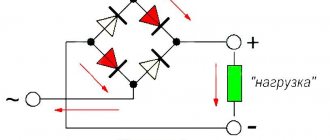
Scheme of operation of a diode bridge Source promkomrostov.ru
Various types of welding rectifiers
Depending on the model, various schemes may be used for this purpose. The following types of rectifiers are used:
- Operating on the basis of a transformer.
- Built on the use of transistors that provide rectification and smoothing of the current.
- Diode bridges.
- Using a choke, which is designed to contain sudden surges in current and voltage.
- Based on the use of thyristors.
- Inverter converters, which increase the frequency, bring the current and voltage to the parameters required for operation.
The use of a diode bridge is considered one of the most effective methods of obtaining current with the parameters required for operation.
The following video describes how to assemble a diode bridge:
Video description
How to assemble a diode bridge
There are also other ways to classify welding equipment. The one that is based on the use of various types of characteristics is often used:
- Rectifiers, which are characterized by steep characteristics, are usually used for manual arc welding. They are also used for working with non-consumable electrodes in a special gas environment. Such a device is capable of creating radio interference, which is suppressed by using appropriate filters.
- Devices with rigid characteristics are used to work with electrodes that melt in carbon dioxide.
- Universal devices can be used for all types of welding work.
These devices must be distinguished by the strength of the current used. Power diodes are designed to operate in cases where it is significant. Industrial level welding machines designed for a three-phase voltage of 380 V can operate with a current of up to 400 A. For single-phase it is 125-180 A.
Operating principle of a welding machine circuit Source ice-people.ru
With your own hands
Practice has shown that some people successfully cope with the independent production of welding rectifiers. The main thing is to develop a workable scheme. The main initial parameters will be the diameters of the electrodes with which the rectifier is designed to work. So, for example, if it is 3 mm, then the welding current must be provided at about 150 A, if it is 4 mm. - 200 A.
The diagram must indicate the parameters of the following elements:
- Transformer. It is advisable to select a circuit from ready-made devices. However, this condition is not easy to fulfill; you have to learn how to make a transformer yourself. Calculating its elements (core cross-section, number of turns on the windings and wire sizes) is not that complicated. Assembly and installation experience is quickly gained after one or two unsuccessful rewinds.
- Rectifier block. Voltage is supplied after the secondary winding of the transformer. The following elements are used for operation: diodes;
- capacitor;
- throttle.
The diodes are assembled using a bridge circuit. After it, the current is not alternating, but pulsating. This current is not suitable for welding, so there is a capacitor in the circuit. It smoothes out pulsations. Finally, direct current is obtained using a choke. The inductor works as a filter that allows the direct current component to pass through and blocks the variable current component.
Welding rectifier BLUE WELD KING TIG 200
Diodes operating at such high currents generate a lot of heat. Therefore, they are necessarily included in the assembly complete with cooling radiators
It is important to consider forced airflow of the welding machine from a fan
The capacitors for the welding unit are designed for the maximum ripple voltage. For the rectifier unit, they differ from those used in radio engineering, which do not work with pulsed currents.
Important! Pay close attention to the characteristics. To make a choke, you need a core made of transformer iron and an insulated copper busbar (you can use a core twisted from tinned copper wires with insulation). The cores can be used from old radio equipment
The choke core and winding are assembled with a gap. After testing the device, the gap and number of turns in the winding can be adjusted
The cores can be used from old radio equipment. The choke core and winding are assembled with a gap. After testing the device, the gap and number of turns in the winding can be adjusted
To make a choke, you need a core made of transformer iron and an insulated copper busbar (you can use a core twisted from tinned copper wires with insulation). The cores can be used from old radio equipment. The choke core and winding are assembled with a gap. After testing the device, the gap and number of turns in the winding can be adjusted.
Welding rectifier base. The textolite plate has excellent insulating properties. It is not advisable to place devices on it close to each other. During operation, a large amount of heat is generated, so it is necessary to have a sufficiently large ventilated space.
There are many options for making a welding rectifier with your own hands. They will differ in design due to the way they are regulated. The contractor will develop his own design in relation to the specifics of the work performed.
Pros and cons of using a diode bridge
In some devices, instead of using a diode bridge for a welding machine, a transformer is included in the design. The latter method provides lower quality work. A circuit with a diode bridge allows you to take advantage of the following advantages:
- With its help, the electric arc becomes more stable.
- Current rectification contributes to more economical energy consumption during operation.
- Relatively high efficiency.
- The rectifier not only converts current, but also stabilizes voltage. It allows the welding machine to operate reliably even in cases where the power grid is unstable.
- The amount of spatter is reduced during welding.
- Compared to using a transformer when using a diode bridge, the device has less weight and more compact dimensions.
- Carrying out welding work ensures higher reliability of the connection.
Welding rectifier disassembled Source ice-people.ru
However, the use of diode bridges also has the following disadvantages:
- The parameters of energy coming from the electrical network play an important role. The use of diode bridges puts forward certain stability requirements.
- Higher quality of work is associated with a small loss of power.
- Higher risk of short circuit.
- The use of this method causes an increase in the cost of equipment.
The use of diode bridges for rectification ensures higher welding quality.
The master must constantly monitor the performance of the device Source radioelementy.ru
Types of devices
There are simply a huge number of varieties of the equipment in question on sale, all of them have their own specific advantages and disadvantages. The classification of industrial welding rectifiers is as follows:
- single-phase;
- two-phase;
- three-phase.
A rectifier for three-phase manual arc welding consists of 6-12 diodes, which are often connected in parallel. Two-phase ones are characterized by parallel and series connection of bridges.
Controlled and uncontrolled rectifiers
In addition, classification can be carried out according to the following criteria:
- Output current. With an increase in this indicator, the thickness of the processed metal increases significantly. If the device produces a small current, then it will be possible to process thin elements. Also, too high a current allows the use of a welding machine for cutting metal.
- Adjustment accuracy. As previously noted, the rectifier can be used to set a wide variety of current parameters. The higher the adjustment accuracy, the more optimal working conditions the master can provide for himself.
- Number of outputs for connection. Sophisticated welding equipment can be used to connect multiple electrode holders simultaneously. A similar model may be needed when several welders are simultaneously working nearby. However, due to the complexity of the design, it becomes larger and more expensive.
- Cooling efficiency. Inexpensive models are intended for domestic use, as they can be used for a short period of time. This is due to the fact that the design does not have an effective cooling system. Professional equipment can be used for welding over a long period.
- Design dimensions. As a rule, welding work is carried out on site. Delivery of all equipment may be difficult if it is heavy and large in size. There are compact models on sale that are easy to transport.
Three-phase models are very popular. This is due to the fact that they can be used to work with metal of a wide variety of thicknesses. A single-point rectifier is most suitable for domestic use, since it is used when using only one electrode holder. There are also models on sale that allow you to connect several electrode holders simultaneously.
Universal modern welding rectifiers are produced by a fairly large number of different manufacturers. Brands largely determine the build quality, service life and cost of equipment.
An inverter rectifier is suitable for domestic use. Such models can be characterized as follows:
- The transformer is responsible for reducing the voltage.
- A rectifying unit is installed, which is responsible for supplying constant voltage.
- Next, it is converted to high-frequency alternating electricity.
Welding rectifier
Such equipment requires the use of alternating current. However, due to a significant increase in the frequency of the supplied current, it is possible to use an inverter rectifier to obtain high-quality connecting seams. Due to the significant simplification of the design, the inverters are relatively small in size and are also easy to operate.
How to get the current needed for work
The power supply for the welding machine must meet the requirements of the specific model. There are 2 options:
- Single-phase voltage 220 V. It is often used to operate household welding devices. It provides a less uniform current compared to three-phase.
- Three-phase voltage 380 V. This option is often used when carrying out industrial welding. It is available for domestic purposes, provided that the owner can provide this opportunity. Such devices operate more stably and efficiently.
The frequency in both cases is 50 Hz.
The current regulator for welding is described in the video below.
Video description
CURRENT regulator for welding machine.
A voltage is supplied from the network, which varies according to a sinusoid. It cyclically becomes positive and negative. Entering the primary shell of the transformer, constant changes in current create an alternating electromagnetic field, which excites periodic fluctuations in voltage and current in the secondary winding. The difference is that at the transformer output the power consumption is reduced.
Then the current passes through the diode bridge. Since the input voltage varies according to a sinusoid, positive and negative pulses are received at the input, which alternate with each other. After passing through the diode bridge in the welding machine, the former remain unchanged, and instead of the latter, positive ones pass through, having the same amplitude. Thus, a strongly pulsating voltage of the same sign appears at the output.
In order to smooth out the pulsation, a capacitor unit is used for further processing. Its output produces a constant voltage with a high level of stability.
Diagram and view of a diode bridge consisting of 4 diodes Source radioelementy.ru
Calculation of the cross-section of the wires of the primary winding of the transformer
Diagram of a welding transformer.
The theory of transformers is complex in that it is based on the laws of electromagnetic induction and other phenomena of magnetism. However, without using complex mathematical apparatus, it is possible to explain how a transformer works and whether it can be assembled independently.
The transformer can be manually wound on a metal core assembled from transformer steel plates. It is easier to wind on a rod or armored core than on a toroidal one.
You should immediately note that the image clearly shows the difference in the thickness of the wires: the thin wire is located directly on the core, and a larger number of turns is clearly visible in it. This is the primary winding
The thicker wire with fewer turns is the secondary winding.
Without taking into account the power losses inside the transformer, let's calculate what the current I1 should be in its primary winding.
The ideal network voltage is U=220 V. Knowing the power consumption, for example, P=5 kW, we have:
I1 = P:U= 5000_220=22.7 A.
Based on the current in the primary winding of the transformer, we determine the diameter of the wire. The current density for a household welding transformer should be no more than 5 A/mm2 of wire cross-section. Therefore, for the primary winding you will need a wire with a cross section of S1 = 22.7:5 = 4.54 mm2.
Using the cross-section of the wire, we determine the square, its diameter d without taking into account the insulation:
d2=4S/π=4×4.54/3.14=5.78.
Taking the square root, we get d=2.4 mm. These calculations were performed for copper wire cores. When winding wires with an aluminum core, the obtained result must be increased by 1.6-1.7 times.
For the primary winding, copper wire is used, the insulation of which must withstand high temperatures well. This is fiberglass or cotton insulation. Rubber and rubber-fabric insulation is suitable. Wires with PVC insulation should not be used.
How to choose
The most popular type of factory-made diode bridge is VD306. It is convenient in that it is equipped with the ability to perform smooth adjustments. It should be taken into account that during operation it consumes 12 kW of electricity. The weight of this device reaches 100 kg. This device is most convenient to use for industrial welding.
You can make a diode bridge with your own hands. It is made from power diodes. There can be from two to five of them in the scheme. A self-made diode bridge will cost less, but to create it, a specialist must have a professional understanding of the equipment.
A welding machine designed for three-phase voltage 380 V has the best performance characteristics. However, there is not always an appropriate power supply network available at the place of work. For example, if you need to carry out welding on a summer cottage, it is unlikely that you will be able to provide it with energy.
Such devices are heavier than those that use a single-phase network. The weight of the latter is in the range of 30-80 kg.
For reliable operation of a diode bridge, it is necessary that the voltage and current values used for which it is designed exceed the actual ones by 1.5-2 times. The maximum reverse voltage of the diodes used should be twice as high as that provided by the transformer. Powerful diodes for a welding machine are necessary for trouble-free operation.
Description of the operation of the diode bridge Source radioelementy.ru
Design and principle of operation
How to make a spotter from a welding machine with your own hands
The classic design is represented by a combination of several devices that provide control of current indicators. The main blocks can be called:
- diodes;
- a step-down transformer;
- cooling system, which is often represented by a fan;
- instruments for measuring current indicator;
- regulators of various types.
The device of the welding rectifier allows for high-precision adjustment of current indicators. Unlike the design of a transformer, it can not only increase the current strength, but also make the indicator constant, due to which high arc stability is ensured.
Welding rectifier device
The operating principle of the welding rectifier has the following features:
- The incoming current is initially applied to the primary winding of the built-in step-down transformer.
- Due to electromagnetic induction, the process of decreasing the voltage value and increasing the current on the secondary winding occurs. The circuit of a modern welding rectifier determines the maximum voltage value at idle 48V.
- The generated voltage is supplied to the installed diodes. New models are manufactured using silicon-based diodes. They are installed as a semiconductor, which ensures current flow in only one direction. It is due to diodes that a constant voltage is ensured, since they eliminate fluctuations during the reverse flow of electricity.
- It is worth considering that during operation the diodes heat up significantly. That is why all models of welding rectifiers have a cooling system, which in most cases is represented by fans. When the device is actively used, constant airflow allows you to reduce the temperature of the semiconductors used. Some models are equipped with a sensor that detects system overheating.
- Sensors are installed to monitor voltage. They work in conjunction with the machine and can turn off the device automatically when the voltage is high.
- The regulator is installed so that you can select the voltage depending on the thickness of the metal being welded.
It is quite difficult to create a welding machine rectifier with your own hands, since for this you need to have certain skills in working with electrical engineering. Industrial versions have high operating accuracy and reliability, which will determine their high popularity.
The features of the installed adjustment devices include the following points:
- In most cases, the adjustment is stepwise. It is represented by a sectional winding connection.
- With step adjustment, the step matters. A lever is installed to control the sectional connection of the winding.
- Most models for using high currents have a design that involves cutting off part of the winding. Due to this, the current is supplied in a short circuit.
The above setting is quite rough. There are models with fine tuning, which is based on the use of the choke saturation method: a device is installed between two silicon diodes and a step-down transformer. A choke is a design represented by a combination of several coils through which current is also supplied during operation of the equipment. By switching the position of the regulator, the length of the winding path also changes.
Most models have a large handle on the body, due to the movement of which the screw shaft with the secondary winding of the transformer is driven. By changing its position, the length of the path that the current overcomes is also adjusted. However, this setting is also characterized by low accuracy.
Welding rectifier circuit
Almost all welding rectifiers have a control unit in the form of a combination of various levers and switches. By changing their position, the characteristics of the supplied current are adjusted.
Safety instructions for use
Many types of welding diodes cannot work fully if there is excessive dust. Therefore, they need to be blown out before use. One of the most convenient means for this is using a household hair dryer. With its help, you can not only eliminate dust, but also remove moisture, which affects the electrical characteristics of the equipment. This purge must be carried out at least once a quarter.
Diode bridge for a welding machine Source prosvarku.info
If the welding machine has not been used for a year, it must be warmed up before use. To do this, the device is given the opportunity to work a little in all available modes. The time during which this preparation is carried out must be at least two hours.
During operation, the welding machine consumes a large amount of energy. It is important to ensure that it does not overheat. If its temperature exceeds the permissible level, you need to take a break from work.
It is necessary to check the presence of insulation on all conductive parts. If it is broken, it must be restored. The terminal connections must be secure. During operation, the welding machine must be grounded. If it overheats, one of the following may be the cause:
- There is a short circuit in the transformer winding.
- The cooling fan is not working at full speed.
- The core insulation is broken.
- Due to a malfunction in the secondary circuit of the transformer, the operating voltage is reduced.
If any malfunctions are found, they must be corrected before you start using the welding machine.
Repair of a welding rectifier Source kedrweld.ru
What types of devices are used in welding equipment?
The segment of elements for process equipment - welding power diodes is presented in a variety of options that have unique characteristics and fundamental values for performing the action. Below we provide a detailed specification of diodes for welding equipment.
| Name | Purpose |
| LEDs | A special semiconductor that forms conditional optical radiation in the circuit during the passage of an effective electric current. |
| Rectifier | Internally, these components do not have any resistance (internal view). The amount of resistance will depend directly on the voltage supplied to the diode. |
| IR diode | Used for equipment in the technological part of welding, which provides for remote control of the operation of welding equipment. |
| Photodiodes | The basic principle of operation and direct operation of the component is to convert the light flux into an electrical type. |
| Zener diode | This option is used for a constant source of current supply. The main functional purpose is threshold, that is, achieving a certain voltage value for the device. There is a subcategory of stabistors, which are designed for low powers and voltages. |
| Varicaps (capacitive diode complexes) | The principle of operation of a diode for a welding inverter is similar to a capacitor device. The principle of the effective part of the work lies in the reverse voltage variant, at which the barrier component of the capacitive characteristics changes. |
| Schottky diodes | These types of diodes are characterized by a low voltage drop and a very high speed, which do not accumulate and do not absorb the main characteristics of drives. In the structural part, such diodes have the form of plates, which are covered with a special high-resistivity epitaxial molding film. The main material and component is a silicon base. Schottky diode components are typically used in switching circuits. |
| Thyristors | Two types and technological states are used - open or closed. For the closed method, low conductivity is acceptable, while for the open method, a high category of semiconductor conductivity is acceptable. The functional significance of the diode bridge of a welding inverter lies in the dynamic mode of constant transition from one state to another, moreover, under the influence of the main signal. |
| Immistors | They have a parallel connection option, which uses two thyristors. This option is used for devices with a variable voltage source. |
The main criterion for all types of diode designs is the current value. According to the system described above, there is a division into the following types of diodes, regardless of the name:
- Low power, with an indicator of up to 3 * 102 ma;
- Average power parameter – 3*102 ma – 10A;
- The maximum value is from 10 Amperes.
