Types of measuring instruments
Pressure gauges are compact devices designed to measure excess pressure of a working medium.
With their help, visual control of the technological process is carried out. Process equipment may be destroyed if the maximum value is increased. For many, the problem arises of what types of pressure gauges there are and what they are for. Depending on the type of environment, the method of taking readings and the installation location, the following types are distinguished:
- Depending on the measuring mechanism: membrane;
- spring;
- liquid;
- electrical contact;
- differential.
- showing;
- vibration-resistant;
- technical;
- switches;
The spring device is designed to measure increased load of liquid or gas. The measurement technology is based on the ability to deform under load. An indicator arrow is attached to the spring. In front of the arrow there is a panel with a lined scale.
Another version of such a device is a Bourdon tube. It has the shape of a hemisphere and, on the one hand, is deaf. The applied load unbends the tube, and the single-turn spring with an indicator arrow rotates around its axis through the straightening angle.
Diaphragm meters differ from spring meters in their measuring principle. They work due to pneumatic compensation. The deflection of the membrane depends on the applied load.
There are many options for measuring mechanisms:
- flat corrugated membrane;
- bellows membrane.
Liquid pressure gauges operate in the form of communicating vessels. In them, two columns of liquid are balanced. We can say that hydrostatic pressure is measured in this way. There is a scale on one of the tubes. The devices have a small measuring range of 10−100 Pa and are therefore used in laboratories.
Electrical contact meters are used to determine vacuum values. These include vacuum gauges and pressure and vacuum gauges. They work with neutral liquids and gases because they are made of steel and brass.
Exemplary pressure gauges, in essence, are standards with the help of which the serviceability of working pressure gauges is checked. They have high precision thanks to the gear transmission mechanism.
Special pressure gauges are so named because they are designed to measure the pressure of gases of one type. For example, acetylene, ammonia, oxygen and others. The purpose of the device is indicated on the front of the device, and its body is painted in a certain color:
- black - carbon dioxide;
- blue - oxygen;
- red - propane;
- yellow - ammonia.
Vibration-resistant instruments are designed to monitor high pressure surges or environments that cause strong vibrations.
Recorders take measurements and immediately record the results in chart form.
Ship pressure gauges measure water and steam in boilers, oil and diesel fuel for the power plant. When working in conditions of high humidity, they must be moisture and vibration resistant.
Railway, as the name suggests, are used in locomotives and rolling stock of railway transport. Their feature is the conversion of the results obtained into electronic and other forms.
Differential devices belong to the category of complex equipment. The operation of the meter is based on the deformation of several blocks included in the tracking mechanism. The readings are determined after the blocks are balanced, when the arrow stops moving.
Each device has measurement errors and pressure gauges are no exception. They are divided into several accuracy classes:
- 0,15;
- 0,25;
- 0,4;
- 0,6;
- 1,0;
- 1,5;
- 2,5;
- 4,0.
Differential pressure gauges
Cost - 1300 rubles including VAT.
Differential pressure gauge (pressostat, differential pressure gauge)
Functions and Application:
- Monitoring the degree of filter contamination - measuring the difference in air pressure before and after the filter.
- Monitoring the operation of a fan group with a V-belt drive - signaling the lack of air pressure on the fan by measuring the pressure on the suction side and at the fan outlet.
- Monitoring the operation of a fan group with direct drive when the unit has an electric heater.
Device:
- The spring membrane, when disconnected from a given pressure difference, causes a corresponding switching using a mechanical block of electrical contacts (a signal about filter contamination or a signal about the operation of the fan group).
- Housing: polymer material.
| NDPS2002 (DPS500) - Pressure range 30 ... 500 Pa. Case material: ABS polymer. Environment -20 to +60С. Protection degree IP54. Rated voltage 250V AC (max current 3A). The output signal is a voltage-free contact, respectively NO or NC. |
| CPS - Pressure range 20 ... 330 Pa. Case material: ABS polymer. Environment -15 to +80С. Accuracy +/- 15% Protection degree IP54. |
Software
The software for differential digital pressure gauges DMC-01 is divided into two parts:
1. A metrologically insignificant part, consisting of external software (for modification M), used for visual presentation of measurement results on the screen of a personal computer, reading measurement results from the memory of pressure gauges, as well as maintaining a data archive. For modification A, measurement results can be collected by any terminal program, for example, using HyperTerminal, which is included in the standard delivery package of the Microsoft Windows operating system.
2. Metrologically significant part, consisting of internal software. The operation of the embedded software is controlled by a microprocessor located inside the device body on an electronic board. Metrological data is processed on the basis of a strictly defined algorithm without the possibility of changing it.
Software protection is achieved by writing a protection bit when programming the microprocessor during the production process of the pressure gauge. When set, the security bit prevents the firmware code from being read, so modification of the software (intentional or unintentional) is not possible. The protection bit can be removed only when the microcontroller memory is completely cleared along with the program located in its memory.
The liquid crystal display of the pressure gauge is used to display information.
Identification of the built-in software can be done when the pressure gauge is turned on, and external software can be identified when the program is launched on the PC. The firmware version number is indicated on the liquid crystal display of the pressure gauge, and the external software version number is indicated in the “About” tab.
The significant part of the software version number is the first digit. The numbers in the number after the dot indicate software modifications that consist of changes that are not significant for the technical characteristics (for example, changes in the fonts of the displayed information, the order in which it is displayed on the display and in the program window, etc.) or the elimination of minor software defects.
Information about identification data of external software for pressure gauges of modification M.
| Name | Identification | Version number | Digital | Algorithm |
| software | Name | (identificational | identifier | calculations |
| provision | software | number) program | software | digital |
| provision | provision | provision | identifier | |
| (check sum | software | |||
| executable code) | provision | |||
| DMC-01 M PO | DMC MEM.exe | 3.11 | 14A8339F | CRC32 |
Learn about microcontroller-based firmware identification information.
| Name | Identification | Version number | Digital | Algorithm |
| software | Name | (identificational | identifier | calculations |
| provision | software | number) program | software | digital |
| provision | provision | provision | identifier | |
| (check sum | software | |||
| executable code) | provision | |||
| DMC-01 A | dmc 01A.hex | 1.09 | BCEA5B60 | CRC32 |
| DMC-01 O | dmc 01O.hex | 1.30 | 4D21A91A | CRC32 |
| DMC-01 M | dmc 01M rs m t.hex | 4.21 | 5DAC0D0C | CRC32 |
The level of protection of the software of differential digital pressure gauges DMC-01 from unintentional and intentional changes corresponds to level A according to MI 3286-2010.
To protect against unauthorized opening of the device, special seals are glued at the junction of two parts of the plastic case and on one of the screws under the back cover of the battery compartment, which are destroyed when trying to open the device.
On the back plate with the name of the device, its serial number and production date, in the places where parts of the device are screwed together, there is a special perforation, which is destroyed when you try to open the device.
Places for gluing a special seal and perforation of the rear nameplate are shown in Fig. 2.
What kind of sensor is this and when is it used?
An electric contact pressure gauge is a sensor that is used to measure excess and vacuum pressure in various media (liquid, gas, steam), is used as a direct-acting signaling device and allows you to control production processes, while a special condition for the medium is to prevent its crystallization.
The ECM is used to issue control signals to actuators that maintain pressure values in the pipeline, as well as compressor units, hydraulic systems, pneumatic equipment or household autoclaves at a certain value.
The electrical contact pressure gauge is popular in many industries and infrastructure systems:
- Energy;
- Metallurgy;
- Oil and gas and petrochemical industry;
- Water supply systems;
- Mechanical engineering installations;
- Heat generation and distribution.
ECMs are also in demand in safety automation systems of thermal power plants, central heating stations and boiler houses.
Types of sensor models
There are many manufacturers involved in the production of electrical contact pressure gauges; some offer a fairly wide range of models; the list below is divided according to various manufacturing plants:
- TM (TV, TMV), 10th series;
- PGS23.100, PGS23.160;
- EKM100Vm, EKM160Vm;
- TM-510R.05, TM-510R.06, DM2005Sg and its analogue TM-610.05 ROSMA.
All of the listed models are divided into pressure gauges with microswitches and with magnetomechanical contacts. Manufacturers also produce devices that are explosion-proof and vibration-resistant or liquid-filled (filled inside with dielectric oil, most often glycerin) so that the readings of the pressure gauge needle do not “jump” with increased pulsation of the measured medium. Glycerin inside the ECM will prevent the needle from moving quickly.
Operating principle of electrical contact pressure gauges
The principle of operation of the ECM is that a moving contact closes or opens a certain set value. The movable contact of an electric contact pressure gauge is a pressure indicating arrow, which rotates when the pressure in the measured medium changes. The setpoint (adjustable) value is set manually using two arrows (minimum and maximum value). These pressure gauge needles are stationary after setting the values.
The value of the moving arrow in the working process, as a rule, is between two setpoints, but when it crosses the limit value, the contacts of the internal electrical circuit are closed or opened (depending on the type of model). These contacts can be used in various relay circuits to control, for example, pneumatic or solenoid valves, as well as magnetic starters of various motors.
Each electrical contact pressure gauge has a marking that describes all its characteristics and type.
How to measure pressure correctly
There are different pressure gauges, therefore, their operating principle is different. Using a pressure gauge is easy, no matter what type of mechanism you have in your hands. In order for the data to be highly accurate and not have to take repeated measurements, you must adhere to some rules:
- Measurements should be carried out on completely cooled wheels. After driving the car, you must wait at least 3 hours. This is due to the presence of a relationship between the pressure and temperature of gases that are in a confined space. In a heated wheel, the pressure will be 15% more than its real value. In winter, the measured indicator will be underestimated by approximately 10%.
- Monitoring must be regular. On worn tires that are used intensively, it is advisable to take measurements before each ride. In other cases, it may be wise to check every week.
- Digital devices can take measurements the moment the system is disconnected from the nipple. This situation is explained by recalibration. In such situations, it is the final reading that will be most accurate.
- In the case of tires that differ from standard ones, you need to rely on the recommendations of the rubber manufacturer.
- It is correct to take measurements in a car that is not loaded. With a load, the pressure should be higher than normal.
- To move on sand, you can set the pressure slightly lower than normal. In this case, it will be easier for the car to move along such a road, the grip on the road will become more confident and the vehicle’s cross-country ability will increase. Rocky soil, snow crust and puddles are not a reason to experiment with tire performance.
Don’t neglect buying a pressure gauge, because tire pressure needs to be constantly monitored. A low, as well as a high, level will reduce the safety of movement.
#Pressure#How to use#Device
Features of differential micromanometers
These are mobile devices for measuring pressure differences up to 3 kPa. Structurally, these devices consist of one pipe in which adjustment means are installed. The most widely used scheme is an inclined tube. In field conditions, a pocket differential pressure gauge is traditionally used, which is characterized by ease of use, but the modified design negatively affects the measurement accuracy.
Differential pressure gauges are installed in monitoring systems for technical systems and their safety. They occupy a place as a separate device, since they are an integral part of the technological chain, closely interacting with control devices.
Meanwhile, modern products, for example, the already mentioned differential pressure gauge DMTs-01M, provide statistical material on the measured parameters. This device can be supplied with an RS-232 interface, this allows you to connect the differential pressure gauge to a personal computer. As a result, it becomes possible to build an automatic control station with a certain set of dispatch functions based on a relatively small device.
But it should be noted that the price of such a product is quite high, it can reach 35 thousand rubles. Devices with less functionality will, of course, cost less, but their capabilities will remain the same.
Bellows differential pressure gauge
This version of the device is also called indicating. The design of bellows pressure gauges is based on two parts - indicating and bellows. As for the first part, it is, as a rule, represented by a round case with an average diameter of 150-200 mm, inside which is a switch-type tribic-sector mechanism. The division value is usually 1 mbar, which is optimal for measuring process pressure indicators. A differential pressure gauge with a bellows is, in particular, used in heat power and gas supply systems serving non-aggressive media such as nitrogen, argon, air, etc.
The working part of the device is formed by means of deformation of elastic mechanics, consisting of bellows, springs and a torque tube. Actually, the active medium acts on the damper system, which transmits physical signals to the elements of the indicating system. Moreover, the accuracy of bellows devices is quite high, since the mechanics do not perceive interference from negative temperature and humidity factors.
Types of measuring instruments
Instruments for measuring pressure are divided into the following types:
- Thrust and pressure gauges are pressure and vacuum gauges that have extreme measurement limits of no higher than 40 kPa.
- Traction gauges are a vacuum gauge that has a measurement limit of (-40) kPa.
- A pressure gauge is a pressure gauge of low excess pressure (+40) kPa.
- Pressure and vacuum gauges are devices that are capable of measuring both vacuum and excess pressure in the range of 60–240,000 kPa.
- A vacuum gauge is a device that measures vacuum (pressure that is below atmospheric pressure).
- A pressure gauge is a device that is capable of measuring excess pressure, that is, the difference between absolute pressure and barometric pressure. Its limits range from 0.06 to 1000 MPa.
Most imported and domestic pressure gauges are manufactured according to all generally accepted standards. It is for this reason that it is possible to replace one brand with another.
When choosing a device, you must rely on the following indicators:
- The location of the fitting is axial or radial.
- The diameter of the fitting thread.
- Instrument accuracy class.
- Case diameter.
- Limit of measured values.
Diaphragm differential pressure gauges
At the heart of the working group of a membrane pressure difference meter is a sensitive metal plate or other elastic element, but at the same time susceptible to vibrations. By the way, in order to increase sensitivity, membranes are sometimes made corrugated. The device also includes two sealed chambers for measuring pressure, which are connected to each other by a valve block with impulse tubes. The pressure difference in a diaphragm-type differential pressure gauge is recorded by a core rod, which is directly connected to the sensing element. With threshold fluctuations, the rod causes proportional changes in the output signal, which provides the indication effect.
Types of pressure gauges
Wherever it is necessary to control the pressure level, the installation of such devices is necessary. Otherwise, disruption of technological processes cannot be avoided, which, in turn, can provoke a critical situation. There are 7 groups of pressure gauges depending on the expected operating conditions.
Reference pressure gauges
- To check measuring equipment (other pressure gauges).
- They work with minimal error in different environments.
- Accuracy class – from 0.05 to 0.2.
Electric contact
- Provide control and warning when a critical level of destructive load is reached.
- They work with a built-in power supply control mechanism: when critical loads are reached, the equipment is turned off or the pressure is released to a safe level through a valve.
- Can be used in liquid and gaseous media.
General technical
- Can be used in non-freezing environments.
- They have good resistance to vibration.
- Mounted on transport and heating systems.
- Accuracy class – 1.0-2.5.
Self-recording
- Provide visual monitoring of the system status, as well as recording of indicators.
- The data is recorded in the form of a diagram, from which you can track the pressure level over time.
- They are mainly used in food industry enterprises and thermal power plants.
Special
- For use with special gases (e.g. ammonia, argon)
- They are produced in colored cases, which allows them to be distinguished from other devices.
- Accuracy class – from 1.0 to 2.5.
Railway
- For mechanisms serving electric rail transport.
- They are characterized by increased resistance to vibration.
- Constant mechanical impact on the housing does not lead to distortion of the obtained data.
Ship's
- Supplied in a housing protected from external influences and precipitation.
- They can be installed not only on ships, but also on outdoor gas distributors.
- Suitable for liquid and gaseous media.
2.4.3. Differential pressure gauges
Small values of differential pressure can be measured by devices based on elastic and flaccid membranes, bellows, as well as structures combined with other elastic elements. There are a sufficient number of designs, but they have their own characteristics.
One of the simplest, most universal and widely used are differential pressure meters (differential pressure meters) with designs based on membranes and membrane boxes /2-18/. In one of the options (Fig. 2.73) the membrane box 1
, into which “positive” pressure enters through the inlet fitting of the holder
2
, is the sensitive element of the differential pressure gauge. Under the influence of this pressure, the movable center of the membrane box shifts.
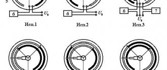
| Rice. 2.73. Indicating differential pressure gauge based on membrane box: 1 – membrane box; |
“Minus” pressure through the inlet fitting of the holder 3
is fed inside the sealed housing
4
of the device and acts on the membrane box from the outside, creating resistance to the movement of its moving center.
Thus, the “plus” and “minus” pressures balance each other, and the movement of the moving center of the membrane box indicates the magnitude of the difference - differential pressure. This shift is transmitted through a transmission mechanism to the index hand 6
, which on the dial scale
7
shows the measured differential pressure.
The range of measured pressure is determined by the properties of the membranes and is limited, as a rule, from 0 to 0.4...40 kPa. In this case, the accuracy class is, as a rule, 2.5 or 1.5.
Mandatory structural tightness of the housing determines high protection from external influences and is determined mainly by the IP66 level.
Beryllium and other bronzes, as well as stainless steel, are used as materials for sensitive elements of devices; for fittings, transmission mechanisms - copper alloys, corrosion-resistant alloys, including stainless steel of various grades.
Devices can be manufactured in small (63 mm), medium (100 mm), and large (160 mm) diameter housings.
meters.
The disadvantages of differential pressure meters (differential pressure meters) based on a membrane box include high requirements for the tightness of the housing and small operating excess pressures, limited by the strength of the housing.
A differential pressure gauge with a vertical membrane (Fig. 2.74) consists of a “plus” 1
and “minus”
2
working chambers, separated by a sensitive corrugated membrane
3
.
4
attached to it .
The linear displacement of the rod in the transmission mechanism 5
is converted into an axial rotation of the tube and, accordingly, the index arrow, which reads the measured pressure on the instrument scale.
| Rice. 2.74. Diaphragm indicating differential pressure gauges with vertical diaphragm: 1 – “plus” camera; |
To maintain the functionality of the sensitive bellows membrane when the maximum permissible static pressure is exceeded, an opening safety valve is provided 6
. Moreover, the designs of these valves may be different. Accordingly, such devices cannot be used when contact of media from the “plus” and “minus” chambers is not allowed.
The high cost of the protective flanges of the membrane, as well as the difficulty of moving the center of this membrane beyond the pressure zone, lead to a relatively high cost of the product and, accordingly, its limited use.
In the design of an indicating differential pressure gauge with a horizontal membrane (Fig. 2.75), the linear movement of the center of the membrane is moved outside the measuring area using metal bellows.
| Fig.2.75. Diaphragm indicating differential pressure gauge with horizontal diaphragm: 1 – “plus” camera; |
Traditional plus 1 and minus 2 cameras, respectively, are placed in a single protective unit 3
, consisting of two parts, between which a corrugated membrane
4
.
A pusher 5 is fixed in the center of this membrane, transmitting movement from the membrane through sector 6
, trib
7
to arrow
8
.
In this transmission link, the linear movement of the pusher is converted into axial rotation of the arrow 8
, which tracks the measured pressure on the dial scale
9
.
This design uses a bellows system for removing the pusher from the working pressure zone. The separating bellows 10
with its base is hermetically attached to the center of the sensitive membrane, and with its upper part it is also hermetically attached to the inlet block. This design eliminates contact between the measured and the environment.
The design of the input block provides the possibility of washing or purging the “plus” and “minus” chambers and ensures the use of such devices for operation even in contaminated working environments.
In the design of a differential pressure gauge with a horizontal membrane, the additional installation of two metal bellows increases the reliability of the design, but significantly reduces its metrological characteristics.
A type of differential pressure gauge with a horizontal membrane and two metal bellows is the design shown in Fig. 2.76. Membrane 1 is fixed between two flanges 2 and 3. A pusher 4 is installed at the center of the membrane 1, the end of which is movably connected to the rocker arm 5. The displacement of the center of the membrane 1 through the pusher 4 is transmitted to the rocker arm 5, the movement of the end of which is an indicator of the magnitude of the measured difference. The separation of the zone of measured pressure from the external environment is carried out using an elastic seal 6.
Subsequently, the movement of the end of the rocker 5 to the index arrow is transmitted using a tribic-sector mechanism.
Positive pressure is supplied to input 7, negative pressure to input 8.
Rice. 2.76. Diagram of a membrane differential pressure gauge with an elastic outlet seal: 1 – membrane; 2 – lower flange; 3 – upper flange; 4 – pusher; 5 – rocker arm; 6 – elastic seal; 7 – positive input; 8 – negative input.
In the design of a membrane differential pressure gauge with an elastic outlet seal, the maximum operating excess pressure is determined by the properties of the rocker arm seal. The higher the mechanical properties of such a seal, the greater the operating excess pressure, but the worse the metrological characteristics.
A two-chamber differential pressure measurement system is used in the design of the device shown in Fig. 2.77. The measured flows of the medium are directed to the “positive” 1
and a “minus”
2
working chambers, the main functional elements of which are autonomous sensitive membranes.
The predominance of one pressure over the other leads to linear movement of the transmitting rod 3
, which is transmitted through the rocker arm
6,
respectively, to sector
4
, tribka
5
and the dial indicator system of the measured parameter.
Differential pressure gauges with a two-chamber measurement system are used to measure small differential pressures under not very high static loads, viscous media and media with solid inclusions.
The magnetomechanical principle of converting differential pressure into a reading system on a circular scale and organizing a control system, due to its convenience and simplicity of design, relatively low cost and high reliability, has been actively used in modern measuring instruments.
| Fig.2.77. Diaphragm two-chamber indicating differential pressure gauge: 1 – “plus” camera; |
The operating principle of a differential pressure gauge with a magnetomechanical signal conversion system/2-28/ is shown in Fig. 2.78. Rotating magnet 1
, at the end of which an arrow
2
, is placed in a housing
3
made of non-magnetic metal.
The mechanical piston 4 with a magnet attached to it, sealed with a fluoroplastic seal 5
, can move in the working channel
6
.
The mechanical piston 4
on the negative pressure side is supported by a plug
7
, which in turn is pressed by a range spring
8
.
Rice. 2.78. Diagram of a differential pressure gauge with a magnetomechanical transducer: 1
– rotary magnet;
2
– arrow;
3
– body;
4
– mechanical piston with a magnet attached to it;
5
– fluoroplastic seal;
6
– working channel;
7
– plug;
8
– range spring;
9
– block of electrical contacts.
The positive pressure medium acts on the mechanical piston through the corresponding supply fitting and moves it along with the plug 7
along channel
6
until such a displacement is balanced by counteracting forces - “minus” pressure and a range spring. The movement of the mechanical piston 4 with a magnet attached to it leads to the associated magnetic interaction with the angular movement of the rotary magnet 1 and, accordingly, the index arrow 2. Thus, the measured pressure difference is converted into the angular movement of the index arrow.
Coordination of the scale range with the angular movement of the pointer is achieved by selecting the elastic characteristics of the range spring 8.
In a number of designs, the fluoroplastic seal 5 is replaced with an elastic membrane, which increases the reliability characteristics of the device.
The differential pressure gauge with a magnetomechanical transducer has a block 9
, closing or opening the corresponding electrical contacts when passing near its mechanical piston with a magnet. The operating principle of such contacts is described in more detail in section 3.1.
One of the main design problems of differential pressure gauges operating at high excess pressures is the possibility of transmitting linear movement of the sensing element or part of it through the protective shell of the device. When measuring small pressure differences, the sensitive elements - these are, as a rule, membranes - develop very small adjustment forces, which structurally makes it difficult to transmit their linear movements through the protective shell of the device.
Devices with a magnetomechanical system for converting the linear movement of the piston into the axial rotation of the tube and an indicating arrow mounted on it ensure the transmission of the linear movement of the piston through the protective shell of the device through the interaction of magnetic fields and subsequent conversion into mechanical movement outside this shell.
Increasing the sensitivity of devices with a magnetomechanical conversion system is achieved by increasing the area of the element separating the “plus” and “minus” pressures. Such an element, which is a separator of different pressures and at the same time a primary converter, can serve as a membrane, as in the design shown in Fig. 2.79. The main elements of the system are identical to those presented in Fig. 2.78. The difference lies in the membrane 10, which separates the “plus” and “minus” pressures. The movement of the center of this membrane through the pusher 11 is transmitted to the piston with a magnet attached to it.
Fig.2.79. Diagram of a differential pressure gauge with a magnetomechanical transducer for measuring small pressure drops:
10
– membrane;
11
– pusher;
12
– plug.
Plug 12 is used for servicing the device, installing or changing the range spring.
Devices with magnetomechanical transducers are resistant to high static pressure - up to 40 MPa. At the same time, they provide measurement and control of differential pressure from 0 to 0.25 kPa...7 MPa with a relatively small error (about 2%).
The device body is made of non-magnetic metals such as stainless steel, Monel alloy, aluminum, copper alloys, synthetic materials. The material is selected based on operating conditions and properties of the measured medium. The seal material of the magnetic piston and membrane is also determined. It uses stainless steel (SS316,SS302) for the plug and range spring, nitrile rubber (Buna-N), fluorinated rubber (Viton) and ethylene propylene rubber (EPDM).
Varying the materials used in the design of devices ensures the applicability of such devices for various gases, including flammable gases such as propane-butane, media of different aggressiveness.
Models of devices with a magnetomechanical system in housings of 63, 80, 100, 150 mm provide indication functionality (display on a digital scale with a certain error) of the measured pressure difference, and can also be supplemented with electrical contact blocks in various designs. The designs of signaling groups of devices with magnetomechanical systems are described in more detail in Section 3.1.
As an example, Fig. 2.80 shows a view of a differential pressure gauge DP in a 63 mm housing (DP63).
Fig.2.80. View of a differential indicating pressure gauge with a magnetomechanical
converter
Active differential pressure gauges with a magnetomechanical converter are used to monitor clogging of filters on flow lines, the appearance of additional hydro- and aerodynamic resistance on operating equipment, including flow meters, shut-off devices, etc.
Security group
A safety group is placed on the supply pipeline at the outlet of the boiler. She must control its operation and system parameters. Consists of a pressure gauge, automatic air vent and safety valve.
The boiler safety group is placed on the supply pipeline before the first branch
The pressure gauge makes it possible to control the pressure in the system. According to recommendations, it should be in the range of 1.5-3 Bar (in one-story houses it is 1.5-2 Bar, in two-story houses it is up to 3 Bar). If you deviate from these parameters, appropriate measures must be taken. If the pressure drops below normal, you need to check if there are any leaks, and then add some coolant to the system. At increased pressure, everything is somewhat more complicated: it is necessary to check in what mode the boiler is operating, whether it has overheated the coolant. The operation of the circulation pump, the correct operation of the pressure gauge and the safety valve are also checked. It is he who must discharge excess coolant when the threshold pressure value is exceeded. A pipe/hose is connected to the free branch pipe of the safety valve, which is discharged into the sewer or drainage system. Here it is better to do it in such a way that it is possible to control whether the valve works - if water is discharged frequently, you need to look for the reasons and eliminate them.
Testo models
is one of the leading developers of measuring and metrological devices. The differential pressure gauge segment is represented by several series, which are used in ventilation systems, gas pipelines, boiler automation and other equipment. Among the most popular models of this brand is the Testo 510 differential pressure gauge, operating in the range from 0 to 100 hPa. The device is quite simple, both in physical handling and in managing electronic functionality. There are magnets on the surface for easy installation, and through the ergonomic operating panel the user can configure the device for different measurement modes, also connecting means of compensation for temperature and air density.
Models from Testo
The company is one of the leading designers and manufacturers of various types of measuring systems. Differential pressure gauges are represented by model ranges that are installed in ventilation systems, gas pipeline systems, heating networks, etc. Testo 510 is rightfully considered one of the most popular devices from this company.
It is capable of operating in a working pressure range from 0 to 100 hPa. This device is easy to use and maintain. The case is equipped with magnets that ensure its tight installation.
General information
Liquid and gaseous substances act with a certain force on bodies in contact with them. The magnitude of this effect, depending on the properties of the substance and external factors (temperature, compression, etc.), is characterized by the concept of pressure.
Pressure is the ratio of the force acting perpendicular to the surface to the surface area, provided that the force is uniformly distributed over the entire area. A distinction is made between absolute and gauge pressure.
Absolute pressure is the total pressure of a gas or liquid taking into account all acting forces, including atmospheric air pressure. Excess pressure is the difference between absolute and atmospheric pressure, provided that the absolute pressure is greater than atmospheric pressure. In technology, as a rule, excess pressure is measured.
Absolute pressure may be less than atmospheric pressure. If their difference is small, then it is called rarefaction; if it is large enough, it is called vacuum.
Pressure gauges are used to measure excess pressure, which is why this pressure is often called manometric pressure. Rarefaction and vacuum are measured with vacuum gauges, and atmospheric pressure with barometers.
The SI unit of pressure is newton per square meter (N/m2). However, manufactured devices are still calibrated in old units - millimeters of water column (mmHg), millimeters of mercury (mmHg) and technical atmospheres (kgf/cm2).
One technical atmosphere is equal to the pressure per area of 1 cm2 of a mercury column with a height of 735.56 mm at a temperature of 0 ° C or a water column with a height of 10 m at a temperature of 4 ° C, i.e. 1 kgf/cm2 = 735.56 mm Hg. Art. = 104mm water. Art.
Vacuum is measured as a percentage of atmospheric pressure or in the same units as pressure. The average value of atmospheric air pressure was determined as a result of numerous measurements and is 760 mm Hg,
Differential pressure gauge device
Most models contain a whole complex of pressure gauge parts, functional components and tubes for communication between media. It is also mandatory to have several measuring chambers, which are separated from each other by manometric devices. In a typical operating scheme, these devices perform the functions of a sensitive element that records the pressure difference. A change in state with an oscillation of one or another characteristic in one of the media gives a signal and the indication mechanism is activated. Again, the means of expressing data for a differential pressure gauge differ, as do the reactions to changes in the system in principle. The device body is made of protected materials - high-strength plastic or metal with an anti-corrosion coating. The housing may also have special elements for installation, transportation or location in viscous and aggressive environments
The presence of such additions is especially important for device models that are used in the chemical industry
Two-pipe models
These devices are used to measure pressure indicators and determine the differences between them. These are devices with a visible level, which is usually presented in a U-shape. By design, such a differential pressure gauge is an installation of two vertical communicating tubes, which are fixed on a wooden or metal base. An obligatory component of the device is a plate with a scale. In preparation for measurement, the pipes are filled with a working medium.
Next, the measured pressure begins to flow into one of the pipes. At the same time, the second pipe interacts with the atmosphere. During the delta measurement process, both tubes experience the measured pressure. A two-pipe differential pressure gauge with liquid filling is used to measure vacuum, pressure of non-aggressive gases and air media.
Differential pressure gauge
With such a lengthy introduction, I wanted to introduce a new series of articles about various measuring instruments for a wide range of purposes. Next, read about the differential pressure gauge or immediately choose deformation differential pressure gauges for your needs.
The purpose of the differential pressure gauge is implied in its name. A pressure gauge is a device for measuring the pressure of a gas or liquid. Differential means that the device measures the difference between two quantities by comparison. Readers of this site are well familiar with the concept of differential current; there is such a concept for pressure. Unlike absolute pressure, the zero of which is vacuum, differential pressure compares two pressures, one of which is selected as the reference pressure.
For example, you have a tank with liquid or gas pumped into it. The liquid (gas) is under pressure of value X. Over time, the liquid level has dropped, which means that the pressure has dropped to value Y. The difference between these pressures will be the differential pressure, which the differential pressure gauge should show.
In many technological processes, pressure drop is technologically unacceptable and even dangerous. Differential pressure gauges monitor this, moreover, when minimum values are reached, pressure gauges can control shutdown of the process or signal a problem.
The differential pressure gauge works in gaseous media and liquids. Ideally suited and actively used for measuring pressure losses in air conditioning filters, as well as in ventilation systems. Differential pressure gauges are used in heating and water supply systems to measure the pressure difference when passing through pumps and filters.
Monotube models
Single-tube differential pressure gauges are usually used when highly accurate results are required. In such devices, a wide vessel is used, which is subject to pressure with the highest coefficient. The only tube is fixed to a plate with a scale showing these differences, and communicates with the atmospheric environment. In the process of measuring pressure differences, the lowest pressure interacts with it. The working medium is poured into the differential pressure gauge until the zero level is reached.
Under the influence of pressure, a certain proportion of liquid flows into the tube from the vessel. Since the volume of the working medium that moved into the measuring tube corresponds to the volume that left the vessel, a single-pipe differential pressure gauge provides for measuring the height of only one liquid column. In other words, the measurement error is reduced. However, devices of this type are not free from shortcomings.
Deviations from the optimal values may be due to temperature expansion in the measuring components of the device, the density of the working medium and other errors, which, however, are characteristic of all types of differential pressure gauges. For example, a digital differential pressure gauge, even taking into account corrections for density indicators and temperature coefficients, also has a certain error threshold.
Basic classifications
Most differential pressure gauges contain a set of components and parts. With their assistance, communication links between environments are maintained. The device must necessarily include cameras, which are separated from each other by a device, with the help of which measurements are taken. That is, these devices play the role of a sensitive component, which records the pressure difference.
For the manufacture of the housing, polymers or metal with an anti-corrosion coating are used. The housing is equipped with special components that are used for transporting and securing devices at the workplace.
First, we need to separate out the small design differences between different pressure gauges. In practice, stationary and portable devices are used. The first ones are recorded directly at the place where the measurement was taken. The latter are used when examining a particular technological process.
Based on the method of data supply, the following modifications of the device can be distinguished.
Switch
This is the classic representation of analogue measurement products. The resulting value is shown by an arrow moving along the established scale. Such models are highly reliable, but in terms of accuracy, analog pressure gauges are significantly inferior to digital ones.
Digital pressure gauge
This device displays measurement results on the installed monitor. Such products can be equipped with a microchip, which is used to generate commands sent to the actuator. Pressure gauges of this class are installed directly into production lines. The actuators are controlled using electrical signals from 4 to 20 mA.
Diaphragm differential pressure gauge
At the base of this type of differential pressure gauge is a plate made of metal or other elastic material. Sometimes, to increase the efficiency of membranes, they are made corrugated.
The differential membrane device includes two containers designed to measure the parameters of the working fluid. The containers are interconnected by a block, equipped with impulse tubes. The pressure difference can be fixed using a rod. It is connected to the measuring organ. With extreme fluctuations, the rod causes changes in the signal at the output of the device. This guarantees the display of the resulting parameters.
Bellows differential pressure gauge
A differential pressure gauge of this class is often called an indicating gauge. Structurally, it consists of an indicating and bellows part. The display part is a round body. A pointer-type indicator mechanism is installed inside it. The division price of such a device is 1 mbar. Bellows pressure gauges have found their application in heating and water supply systems. In addition, they are installed in gas supply complexes through which neutral gases are transported.
In the working part of the differential pressure gauge, elements of elastic mechanics are installed; they consist of bellows, springs, etc. That is, the active medium affects the damping system, which in turn transmits signals to the indication system. Devices of this class are distinguished by high measurement accuracy, since the mechanics are not susceptible to the effects of temperature and moisture
Mercury differential pressure gauge
It is distinguished by its complexity of design. The operation of this product is based on determining hydrostatic characteristics using a mercury column. Using interacting vessels, the device records pressure differences by assessing and comparing excess levels in liquid columns.
The peculiarity of devices of this type is the density of the working fluid. This minimizes the effect of capillary forces.
Mercury differential devices are distinguished by high sensitivity to temperatures. Therefore, to eliminate temperature effects, adjustment devices are installed on them.
Classification
Due to the complexity of pressure measurement processes, fluid characteristics and further conversion, there are several options for differential pressure gauges to work under different conditions. By the way, a differential pressure gauge, the principle of operation of which is largely determined by its design, is oriented in its design to the possibility of use in specific environments - therefore, the classification is based on this. So, manufacturers produce the following models:
- A group of liquid differential pressure gauges, which includes float, bell, pipe and ring modifications. In them, the measuring process takes place based on indicators of the liquid column.
- Digital differential pressure gauges. They are considered the most functional, since they make it possible to measure not only the characteristics of pressure drops, but also the speed of compressed air flows, humidity and temperature indicators. A prominent representative of this group is the Testo differential pressure gauge, which is also used in environmental monitoring systems, aerodynamic and environmental studies.
- Category of mechanical devices. These are bellows and diaphragm versions that provide measurement by monitoring the characteristics of the pressure sensitive element.
Recommendations for selection
Calculation operations with pressure indicators require the use of a reliable device that best suits operating conditions
In this regard, it is important to determine the list of functions that the device will perform. For example, the Testo 510 differential pressure gauge is capable of providing accurate, temperature-compensated readings and data on a digital display
In some cases, a signaling model is required, so this option should be considered.
For the most correct data, you must first compare the characteristics of the device with the possibility of operation in a specific operating environment. Not all devices can be used in oxygen, ammonia and freon environments. At the very least, their accuracy may be low.
Principle of operation
In most pressure gauges, the technology for determining and calculating data is based on deformation processes in special measuring units, for example, in a bellows unit. This element acts as an indicator that senses pressure changes. The block also becomes a difference converter in pressure indicators - the user receives information in the form of moving the pointer arrow on the device. In addition, data can be presented in Pascals, covering the entire measurement spectrum. This method of displaying information, for example, is provided by the Testo 510 differential pressure gauge, which during the measurement process eliminates the need for the user to hold it in his hand, since there are special magnets on the back of the device.
In mechanical devices, the main indicator is the location of the arrow, controlled by a lever system. The pointer moves until the changes in the system cease to exert a certain force. A classic example of this system is the DM 3538M series differential pressure gauge, which provides proportional delta (pressure difference) conversion and provides the result to the operator in the form of a unified signal.
WIKA models
Another Russian manufacturer offering both standard versions of pressure gauges and highly specialized models with additional options and extended operating ranges. For example, in addition to the main function of monitoring differential pressure, some versions allow you to monitor the condition of pumps, filters, ventilation units and other engineering equipment in the same serviced system. Like Testo differential pressure gauges with digital display, WIKA devices from the DELTA-plus range offer several display options. Various data processing tools with a wide range of operator notification channels are also available to the user. The manufacturer is also developing special versions for use in harsh conditions. These are models made of high-quality resistant materials, protected from high temperatures, humidity and mechanical stress.
Models "ECO-INTECH"
The domestic enterprise also produces pressure meters in several series. For example, the DMTs-01M apparatus belongs to professional equipment, through which it is possible to calculate the differences and degrees of pressure discharge in gaseous media. Special modifications are also offered to control the flow and speed of air flows using proprietary pressure tubes. The features of the differential pressure gauge DMTs-01M include the ability to operate in automatic mode and support for processing operations with ready-made data,
Application of the maximum pressure drop indicator.
The control arrow for the maximum pressure drop (tracking pointer) is an additional arrow on the instrument scale, which serves to indicate the maximum achieved differential pressure of the medium during operation of the device. The main indicator arrow of the device has the ability to move the control arrow in the direction of increasing pressure as the pressure drop increases. When the pressure drop decreases, the main arrow of the device returns towards lower values, and the control arrow remains at the maximum value achieved. To set the maximum value indicator arrow to the zero position, this indicator has a handle located on the outside of the instrument scale.
Differential pressure gauge with control arrow for maximum pressure drop
At remote sites where there is no permanent technological staff, a filter element may break through. The operator, during his next visit to the site, will record a zero pressure drop and may erroneously conclude that the filter is in satisfactory condition. Without a control needle, it is impossible to accurately analyze previous readings, so it is recommended that all devices intended for local indication be equipped with this option.