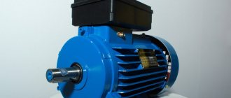
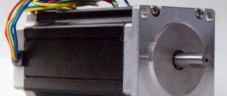
Among the variety of types of electric motors produced today, asynchronous motors have become widespread. Their power and efficiency ensure their use in the woodworking and metalworking industries, in pumping units, factories, machine tools and hand-held power tools.
asynchronous three-phase motor
Asynchronous motor: what is it
An asynchronous motor is an asynchronous electrical machine used to convert electrical energy into mechanical energy. Asynchronous literally means non-simultaneous - here it means that in an asynchronous motor the magnetic field always has a higher rotation speed than the rotor, which seems to be trying to catch up with it. These machines operate on alternating current networks.
Any asynchronous motor consists of two key components: the rotor and the stator. These parts do not contact each other and are separated from each other by an air gap in which a moving magnetic field is formed.
The stator of an asynchronous machine consists of the following parts:
- Frame. Serves to hold all engine parts together. For small engines, as a rule, one-piece cast casings made of cast iron, steel and aluminum alloys are used.
- Core or magnetic conductor. It is assembled from plates, for the manufacture of which special electric steel is used. It is pressed into the housing and improves the magnetic induction properties of the machine. Each core plate is coated with a special varnish to reduce losses when eddy currents occur. In some cases, the design of an asynchronous motor requires the installation of a core housing that combines both functions.
- Windings Installed in the grooves of the core. It consists of three coils of copper wire sections located at an angle of 120˚ relative to each other. It is called primary because it connects directly to the network.
The rotor design consists of a main block with a ventilation impeller, supported by bearings. The connection of the rotor with the driven mechanism is ensured using direct connection, gearboxes or other methods of transmitting mechanical energy. Asynchronous motors use two types of rotors:
- The massive rotor is a single circuit made of a durable ferromagnetic compound. Currents are induced inside it, and it also plays the role of a magnetic circuit in the structure.
- A squirrel-cage rotor (invented by the great Russian engineer Mikhail Osipovich Dolivo-Dobrovolsky, like all three-phase current) is a system of conductors connected by rings, similar in appearance to a squirrel wheel. Currents are induced inside it, whose electromagnetic field interacts with the magnetic field of the stator, causing the rotor to move.
squirrel wheel
We recommend watching this video. Although it is old, it is interesting and educational. It will allow you to close unclear points.
Electric motor design
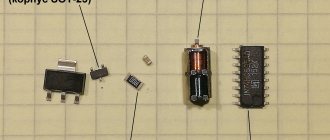
The central process of functioning of a direct current electric motor (DMC for short) is the injection of torque due to the voltage supplied to the rotor coils. The process is made possible thanks to 4 structural elements:
- collector;
- brush mechanism (2 brushes + 2 plates/lamellas);
- the rotor of an electric motor (the armature, in a synchronous motor, has 1 winding);
- the stator on which magnets are installed (in DC motors - constant).
Rotor
The rotor is a moving element of an electric motor, driven by a magnetic field, and performs rotational movements together with the shaft. It has at least 3 teeth, one of which consistently falls into the connection area.
Motor commutator
The rotor switches automatically. The collector is responsible for this function - a structure of two lamellas attached to the rotor shaft and two brushes that act as current-collecting contacts (they supply direct current to the lamellas). The operating principle is as follows:
- the rotor rotates, changing the direction of the current;
- when the anchor makes a 180-degree turn, the slats change places;
- when changing the positions of the plates, both the direction of the current and (accordingly) the poles of the magnet change;
- the poles of the same name, obeying the laws of physics, repel each other - the coil rotates, its poles are attracted to the opposite poles on the other side of the magnet.
Electric motor stator
Stator is a stationary or stationary unit of an electric motor. Another name is inductor . It includes several windings with reversible polarity (when alternating current passes), which ensures the formation of a magnetic field. In most cases, the stator has 2 pairs of main poles, but it can also include auxiliary poles for better switching of the rotor on the commutator.
Three-phase asynchronous motor. Principle of operation
The principle of operation of an asynchronous motor is the relative position of the windings and three-phase voltage, which leads to the emergence of a rotating magnetic field, which acts as a driving force.
In more detail, when power is applied to the primary winding, three magnetic fluxes are formed in the phases, varying depending on the frequency of the input voltage. They are displaced from each other not only in space, but also in time, due to which a rotating magnetic flux appears.
During rotation, the resulting flow creates an emf in the rotor conductors. Due to the fact that the rotor winding is a closed circuit, a current is created in it, creating a starting torque in the direction of rotation of the stator magnetic field. This causes the rotor to rotate after the starting torque exceeds its braking torque. The phenomenon observed at this moment is called slip - a quantity that shows, as a percentage, the ratio of the magnetic field rotation frequency to the rotor rotation frequency. (n1 – stator magnetic field frequency; n2 – rotor rotation frequency)
Slip is a very important parameter. At the start, its value is always equal to 1 and, naturally, becomes smaller as the difference between n1 and n2 increases, which is also accompanied by a decrease in the electromotive force and torque. During idle operation, slip is minimal and increases as the static torque increases. Having reached critical slip (denoted as scr), it can cause the engine to stall. After balancing the braking and electromagnetic torque, the changes in values stop.
Thus, the principle of operation of an asynchronous motor is based on the interaction of the magnetic field of the rotor, which is in rotation, and the currents induced in the rotor by the same field. In this case, a prerequisite for the occurrence of torque is the difference in the rotation frequencies of the fields.
How are calculations made?
In order to calculate the engine speed, you should use the slip formula we previously defined:
And express the rotor rotation speed from it:
As an example, let's take a motor model AIR71A4U2 with a power of 550 W with 4 pairs of poles and a rotor speed of 1360 rpm.
When powered from a network with a frequency of 50 Hz, the stator will rotate at a speed:
Thus, the amount of slip of the electric motor is:
And finally, a wonderful, albeit outdated, video recommended for everyone to watch once.
Source
Single phase asynchronous motor
In fact, any asynchronous electric motor is three-phase and is connected to a three-phase network with a voltage of 380 V. It is called single-phase or two-phase when connected to a single-phase electrical network with a voltage of 200 V, when power is supplied to only two windings. In such a circuit, the main working winding is supplied with a clean phase from the network, and the other is supplied with power through a phase-shifting element, usually a capacitor. This scheme allows you to create the necessary induction to bias the rotor and start an asynchronous motor from a single-phase network. For its further operation, it is not even necessary that the starting winding (which is connected through a capacitor) remain energized.
The fact is that a three-phase asynchronous motor continues to function (under low load) even if during operation the power supply through one of the supply wires is turned off, thus simulating operation from a single-phase network. This is because the resulting magnetic field maintains rotation.
Possible faults
Despite the simplicity and reliability of an asynchronous motor, if used incorrectly and in unfavorable external conditions, they can lose performance or fail. Any malfunctions of a minor or serious nature can be divided into 2 groups - electrical and mechanical.
Mechanical breakdowns
These damages are often noticeable by external inspection or by hearing during operation of the electric motor:
- defects of the housing, impeller;
- weakened fixation of windings;
- shaft deformation.
Bearing wear is also a common problem. To detect a breakdown in a timely manner, it is necessary to pay attention to external signs. Worn elements contribute to vibrations and overheating of the unit. You can also determine the malfunction acoustically - by increasing the noise level when turning on the power.
Two-phase asynchronous motor
It is also possible to create a rotating magnetic field using two-phase windings. To ensure the operability of the circuit, the phases of the windings must be positioned 90˚ offset from each other. When they are powered by currents that are 90˚ out of phase, a rotating magnetic field appears, as in a three-phase machine.
An asynchronous two-phase electric motor is driven by currents generated by the interaction of the resulting field with the rotor rods. It accelerates until the maximum speed of its rotation is reached. To power such a motor from a single-phase power supply, it is necessary to create a phase shift on one of the windings. For this purpose, capacitors of the required capacity are used.
Today, two-phase asynchronous motors with a hollow aluminum rotor are increasingly used. It is given rotation by eddy currents formed inside the cylinder when interacting with a rotating magnetic field.
The rotor inertial moment gives the motor good characteristics for use in some specialized applications, such as bridge control and compensation circuits. One of the windings in them is connected to the supply network through a capacitor, and the control voltage passes through the second.
Clutch analogy
Considering the principle of operation of an asynchronous electric motor used in industrial machines and its technical characteristics, it is necessary to say something about a rotating mechanical clutch. The torque on the drive shaft must be equal to the torque on the driven shaft. Additionally, it should be emphasized that these two torques are one and the same, since the torque of a linear transducer is caused by friction between the discs within the clutch itself.
Electromagnetic clutch
A traction motor with a wound rotor has a similar operating principle. The system of such a motor consists of eight poles (of which 4 are main, and 4 are additional), and a frame. The main poles contain copper coils. The rotation of such a mechanism is due to a gear transmission, which receives torque from the armature shaft, also called the core. Connection to the network is carried out using four flexible cables. The main purpose of a multi-pole electric motor is to drive heavy equipment: diesel locomotives, tractors, combines and, in some cases, machine tools.
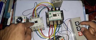
Connection diagrams
In order to connect a three-phase asynchronous motor, several different circuits are used, but the most commonly used are delta and star.
Triangle
The advantage of this scheme is that when connected according to it, a three-phase motor can develop the highest rated power. To do this, the windings are connected according to the end-to-beginning principle, which in the schematic diagram looks like a triangle, but in the form of a triangle it is not always convenient to understand what’s what. Therefore, we offer for analysis the diagram below, and then the photograph already assembled (even lower).
triangle connection diagram
In three-phase electrical networks, the linear voltage between the terminals of the windings is 380 V. In this case, there is no need to create a working zero. It is important to note that in such a circuit a large inrush current can occur, significantly overloading the wiring.
Star
This connection method is the most used in networks with three-phase current 380 V. The name of the circuit is due to the fact that the ends of the windings are connected at one point, like star rays. The beginnings of the windings are connected via switching equipment to the phase conductors. In such a linear design, the voltage between the beginnings is 380 V, and between the junction and the connection of the conductor - 200 V. Below is a diagram, and even lower is a photograph in assembled form.
star connection diagram
A three-phase motor for 380 V networks connected in this way is not able to develop maximum power due to the fact that the voltage on each winding is 220 V. In turn, this circuit prevents the occurrence of overcurrents, which ensures a smooth start.
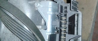
The possibility of connecting the motor in one way or another is usually indicated on its plate. The Y symbol means "star" and the ∆ symbol means "triangle". You can determine the circuit on an already connected machine by the type of windings - one double jumper between them indicates that a “star” is used (first photo from the bottom), and if three jumpers are visible between the terminals of the windings - a “triangle” (first photo from the top).
Asynchronous motor, triangle assembly.
Asynchronous motor, star assembly
In the case when it is necessary to start a three-phase asynchronous electric motor in the opposite direction of rotation, the two supply wires from the three-phase source should be swapped.
A little history
The first such electric motor mechanism appeared back in 1888 and was introduced by the American engineer Nikola Tesla. However, his prototype device was not the most successful, since it was two-phase or multi-phase and the performance characteristics of the asynchronous motor did not satisfy consumers. Therefore, it was not widely used.
But thanks to the Russian scientist Mikhail Dolivo-Dobrovolsky, it was possible to breathe new life into the invention. It was he who took the lead in creating the world's first three-phase asynchronous motor. This design improvement was revolutionary, since the operating principle of a three-phase asynchronous motor made it possible to use only three wires for operation, rather than four. So there were no more obstacles left for the smooth launch of the device into mass production.
Today, due to their simplicity, these machines are widely used, and the mechanical characteristics of the asynchronous motor suit all drivers.
Ease of use, the principle of operation of an asynchronous motor, easy starting, reliability and low cost, helped these motors spread throughout the world and literally make a technical revolution in industry.
The operating principle of a three-phase motor is based on power from three phases of alternating current in a standard network. To operate, it requires exactly this kind of electricity and that is why it is called three-phase.
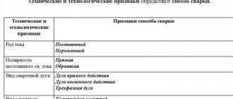
Functional and operational features
Characteristic advantages of asynchronous motors:
- Their design does not contain collector groups, which increase wear on other types of engines due to additional friction.
- Power supply of asynchronous electrical machines does not require the use of converters and can be provided by an industrial three-phase network.
- Due to fewer parts and structural elements, they are relatively easy to maintain and have a long service life.
Among the disadvantages are:
- The scope of application of asynchronous motors is somewhat limited due to the low starting torque.
- The high reactive power they consume during operation does not affect the mechanical power.
- The large inrush currents consumed when starting these motors may exceed the allowable values of some systems.
Soft starter
Soft starting devices for asynchronous motors have their own specifics. It is used to smoothly start or stop electromagnetic motors. Can be mechanical, electromechanical or completely electronic.
The starting characteristic of an asynchronous motor is designed:
The operating principle and operation of a soft starter are based on a wide variety of variables. As a result, greater opportunities arise for controlling operating modes.