Turning on machines
TO
category:
Turning
Turning on machines
Next: Drilling and boring machines
Turning is carried out on turning machines, as well as on boring, aggregate and combined machines.
The concept of “turning” combines the following main types of work: turning cylindrical, conical and shaped surfaces; turning and trimming end surfaces; cutting; boring of cylindrical, conical and shaped holes.
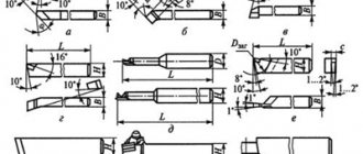
Grinding is divided into rough and finishing. During rough turning, a significant amount of chips is removed; normal allowance is usually 2-5 mm. As a result of rough turning, accuracy classes 2–7 and cleanliness classes 1–3 are achieved. Grinding is done with passing cutters. Passing cutters are divided into roughing and finishing. Rough straight right (a) and left (b), bent right (c) and left “(d) are used for rough turning of workpieces. The angles of the roughing cutters and the radius at the apex are chosen such as to ensure their greater durability and possibly easier cutting.
Finishing cutters are used for finishing workpieces. There are fine incisors with large rounding (e, e) and wide incisors (g). Allowances for finishing turning (Fig. 258, e, f, g) range from 1-2 mm or less per side. The feed rate when finishing turning with cutters with a rounded cutting edge should be small (usually s = 0.2 mm/rev), and when turning with wide cutters it can be larger (s = 3-30 mm/rev). As a result of finishing grinding, accuracy classes 2–4 and cleanliness classes 4–8 are achieved.
Rice. 1. Six-spindle bar machine
Grinding of the end surfaces is carried out using roughing and finishing cutters. When processing such surfaces of workpieces mounted on the centers of lathes, scoring cutters are used.
Rice. 2. Turning cutters and the operations they perform
Cutting off parts of workpieces, as well as turning annular grooves, is done with cutting tools (Fig. 2, j).
Boring of pre-drilled holes or holes obtained during procurement operations is carried out with roughing (Fig. 2, l) and finishing (with a rounded cutting edge) cutters. Boring cutters for through holes (l) have a leading angle cp less than 90°; for boring cutters for blind holes (m), this angle is equal to or slightly greater than 90°.
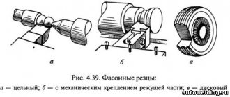
Shaped cutters are round (n) and prismatic (o). The shaped group also includes threaded cutters (p, p). Round cutters are easy to manufacture and are widely used in the processing of external and internal shaped profiles. Prismatic cutters are somewhat stronger than round cutters, but they can only be used for processing external surfaces. The fastening of the prismatic (o) cutter in the frame is reliable. During regrinding (which is carried out only on the front surface), the working profile of both disk and prismatic cutters remains unchanged. Shaped cutters are especially widespread in mass and large-scale production. Threaded cutters are also often made round.
Grinding of conical surfaces can be carried out with a wide cutter; with the upper caliper slide turned; with the tailstock shifted; using a copy ruler.
Rice. 3. Grinding the cone by turning the upper slide
A wide cutter can be used to grind conical surfaces no longer than 15 mm.
When turning conical surfaces by turning the upper slide, the lower slide remains stationary, and the feed is carried out by the upper slide manually or automatically (on large machines). The length of the cone in this case is limited by the stroke length of the upper slide. The rotating part of the caliper must be rotated through an angle a equal to the angle of inclination of the cone generatrix to the cone axis.
With the tailstock shifted, cones with small angles a can be turned, since the maximum amount of shift of the headstock in the transverse direction is relatively small (up to 20 mm
The method of turning cones using a copying ruler (Fig. 4, b) is the most universal; it provides the possibility of obtaining higher accuracy of angles. The thrust constantly presses the slider to the ruler, since the force of Ru tends to push the cutter (and with it the entire upper part of the support; away from the workpiece. The plate is attached to the machine bed and has a scale for setting the ruler at the desired angle.
Rice. 4. Grinding the cone using the method of transverse shift of the tailstock (a) and using a copy ruler (b)
Boring of internal cones can be done with a wide cutter, by turning the upper slide and using a copy ruler using appropriate cutters.
Cutters for high-speed processing of metals. Equipping cutters with plates made of metal-ceramic hard alloys and mineral-ceramic plates provides the possibility of a sharp increase in labor productivity by increasing cutting speed.
Currently, cutters with a chamfer and positive rake angles are widely used for high-speed cutting.
In Fig. 5, a shows a cross-section of G. S. Bortkevich’s cutter, and in Fig. 5, b - cross-section of P.B. Bykov’s cutter. Negative angles along the cutter chamfer contribute to significant strengthening of the cutting edge. Cutting speeds when working with such cutters are often adopted by innovators above 1000 m/min.
Another progressive processing method that is widely used in semi-finish turning is high-speed machining with high feeds.
Rice. 5. Incisors by G. Bortkevich and P. Bykov
Rice. 6. Cutter V. Kolesova
The use of this method gives high productivity, increases the accuracy and cleanliness of machined surfaces while increasing the power utilization of machine tools. Innovative turner V. A. Kolesov proposed a method of power cutting (the use of high feeds - 3, 5 and even 30 mm/rev) of metals for more complete use of the power of relatively low-speed machines, as well as when processing parts of relatively small diameters (50-100 mm). The cutter by V. A. Kolesov is characterized by the presence of three cutting edges AB, BC, and CD, which provide more favorable conditions for chip formation. The CD edge is parallel to the feed direction and has a length of 1.1-1.2 s, as a result of which the machined surface does not have ridges and is quite clean (V5-V6).
Metalworking – Mechanical – With chip removal – Metal blade tools – TurningTurning (boring) is a method of processing a workpiece with a metal single-edged tool.
Technological parameters:
- t = from 0.03-0.05 to 7-8 mm, sometimes t = 0.002-0.006 mm;
- S = 0.05-0.1 to 1.5-2 mm/rev; (see tables No. 1-5)
- V = from 1-2 to 150-1000 m/min; (see tables No. 6-8)
- cutting forces Pz = from 10-15 to 800-900 kgf.
Turning (boring) is carried out on machines :
- Lathes
- Revolver
- Boring
- Carousel
- Automatic and semi-automatic lathes (single- and multi-spindle) with horizontal and vertical spindles
- Multi-cutting lathes
- Automatic hydrocopying lathes
- and etc.
The achieved accuracy is from 14-13 qualifications (7-5th grade) to 9-7th qualification (3-2a grade). Under more careful processing conditions - up to 5-6th quality (1st-2nd grade).
Surface roughness from class 2-3 for roughing to class 5-6 for semi-finishing; with more careful processing, it is possible to achieve a roughness of 7-10 classes (Ra = 1.25 - 0.16 microns).
Dimensional accuracy and roughness of external cylindrical surfaces when processed on lathes
Type of processing
| Quality | Roughness parameters, microns | ||
| Rz | Ra | ||
| Turning: rough semi-finish finishing thin | 13-12 | 80…60 | — |
| 11-9 | 40…20 | — | |
| 8-7 | — | 2,5 | |
| 7-6 | — | 1,25…0,63 | |
| End cutting with a cutter: rough finishing thin | 12 | 40 | — |
| 11 | 20 | — | |
| 8-7 | — | 2,50…1,25 | |
Deviation from coaxiality of the surfaces of bodies of revolution processed on lathes
| Surface treatment method | Deviation from alignment, mm |
| In centers: from one installation from two installations | 0,008…0,004 |
| 0,015…0,008 | |
| On a mandrel: machined in place (on the same machine) when the deviation from the alignment of the mandrel, spindle and workpiece is no more than ±0.002 mm | 0,008…0,004 |
| 0,012…0,008 |
Types of turning and boring:
- Roughing t = up to 3-10 mm; S = 0.15-1.0 mm/rev; Processing accuracy: 12-14 quality (5-7 grade); Surface roughness: no higher than class 3 (Rz=80 µm); The deformed surface layer can reach a thickness of 0.5-0.9 mm. Scope of application: preliminary (rough) processing of workpieces, removal of the main part of the allowance, surface preparation for subsequent processing.
- Semi-finish t = 0.5-3 mm; S = 0.15-0.7 mm/rev; V = from 5-10 to 100-150 m/min Processing accuracy: 11-12 quality (4-3 class); Surface roughness: 4-6 class (Ra = 10-2.5 microns); Scope of application: preliminary and final surface treatment. Often precedes sanding.
- Finish t = 0.1-1.0 mm; S = 0.1-0.5 mm/rev; V = from 2-5 to 100-200 m/min and more; Processing accuracy: 11-7 quality (4-2a class); Surface roughness: 7-8 class (Ra = 1.25-0.63 microns); Scope of application: final surface treatment, as well as for preparing it for final processing by other methods (superfinishing, honing, lapping).
- Thin t = from 0.002-0.006 to 0.3 mm; S = 0.02-0.12 mm/rev; V = from 100 to 1000-6000 m/min; Processing accuracy: 9-5 quality (3-1 class); Surface roughness: 8-10 class (Ra = 0.63-0.16 µm); Scope of application: final surface treatment.
Table No. 1. Feeds during rough external turning with cutters with inserts made of carbide and high-speed steel.
| Part diameter, mm | Cutter holder size, mm | Processed material | |||||||||
| Structural carbon steel, alloyed and heat-resistant | Cast iron and copper alloys | ||||||||||
| Feed S, mm/rev, at cutting depth t, mm | |||||||||||
| Until 3 | St. 3 to 5 | St. 5 to 8 | St. 8 to 12 | St.12 | Until 3 | St. 3 to 5 | St. 5 to 8 | St. 8 to 12 | St. 12 | ||
| Up to 20 | From 16 x 25 to 25 x 25 | 0,3-0,4 | — | — | — | — | — | — | — | — | — |
| St. 20 to 40 | From 16 x 25 to 25 x 25 | 0,4-0,5 | 0,3-0,4 | — | — | — | 0,4-0,5 | — | — | — | — |
| » 40 » 60 | From 16 x 25 to 25 x 40 | 0,5-0,9 | 0,4-0,8 | 0,3-0,7 | — | — | 0,6-0,9 | 0,5-0,8 | 0,4-0,7 | — | — |
| » 60 » 100 | From 16 x 25 to 25 x 40 | 0,6-1,2 | 0,5-1,1 | 0,5-0,9 | 0,4-0,8 | — | 0,8-1,4 | 0,7-1,2 | 0,6-1,0 | 0,5-0,9 | — |
| » 100 » 400 | From 16 x 25 to 25 x 40 | 0,8-1,3 | 0,7-1,2 | 0,6-1,0 | 0,5-0,9 | — | 1,0-1,5 | 0,8-1,3 | 0,8-1,1 | 0,6-0,9 | — |
| » 400 » 500 | From 20 x 30 to 40 x 60 | 1,1-1,4 | 1,0-1,3 | 0,7-1,2 | 0,6-1,2 | 0,4-1,1 | 1,3-1,6 | 1,2-1,5 | 1,0-1,2 | 0,7-0,9 | — |
| » 500 » 600 | From 20 x 30 to 40 x 60 | 1,2-1,5 | 1,0-1,4 | 0,8-1,3 | 0,6-1,3 | 0,5-1,2 | 1,5-1,8 | 1,2-1,6 | 1,0-1,4 | 0,9-1,2 | 0,8-1,0 |
| » 600 » 1000 | From 25 x 40 to 40 x 60 | 1,2-1,8 | 1,1-1,5 | 0,9-1,4 | 0,8-1,4 | 0,7-1,3 | 1,5-2,0 | 1,3-1,8 | 1,0-1,4 | 1,0-1,3 | 0,9-1,2 |
| » 1000 » 2500 | From 30 x 45 to 40 x 60 | 1,3-2,0 | 1,3-1,8 | 1,2-1,6 | 1,1-1,5 | 1,0-1,5 | 1,6-2,4 | 1,6-2,0 | 1,4-1,8 | 1,3-1,7 | 1,2-1,7 |
Notes:
1. Lower feed values correspond to smaller cutter holder sizes and stronger processed materials, upper feed values correspond to larger cutter holder sizes and less durable processed materials.
2. When processing heat-resistant steels and alloys, do not use feeds exceeding 1 mm/rev.
3. When processing discontinuous surfaces and when working with impacts, the table feed values should be reduced by a factor of 0.75-0.85.
4. When processing hardened steels, reduce the table feed values by multiplying by a factor of 0.8 for steel with HRC 44-56 and by 0.5 for steel with HRC 57-62.
Table No. 2. Feeds during rough boring on lathes, turret lathes and rotary lathes with cutters with plates made of carbide and high-speed steel.
| Cutter or mandrel | Processed material | ||||||||||||
| Diameter of the circular cross-section of the cutter or dimensions of the rectangular cross-section of the mandrel, mm | Reach of cutter or mandrel, mm | Structural carbon steel, alloyed and heat-resistant | Cast iron and copper alloys | ||||||||||
| Feed S mm/rev, at cutting depth t, mm | |||||||||||||
| 2 | 3 | 5 | 8 | 12 | 20 | 2 | 3 | 5 | 8 | 12 | 20 | ||
| Lathes and turret lathes | |||||||||||||
| 10 | 50 | 0,08 | — | — | — | — | — | 0,12-0,16 | — | — | — | — | — |
| 12 | 60 | 0,10 | 0,08 | — | — | — | — | 0,12-0,20 | 0,12-0,18 | — | — | — | — |
| 16 | 80 | 0,1-0,2 | 0,15 | 0,1 | — | — | — | 0,2-0,3 | 0,15-0,25 | 0,1-0,18 | — | — | — |
| 20 | 100 | 0,25-0,3 | 0,15-0,25 | 0,12 | — | — | — | 0,3-0,4 | 0,25-0,35 | 0,12-0,25 | — | — | — |
| 25 | 125 | 0,25-0,5 | 0,15-0,4 | 0,12-0,2 | — | — | — | 0,4-0,6 | 0,3-0,5 | 0,25-0,35 | — | — | — |
| 30 | 150 | 0,4-0,7 | 0,2-0,5 | 0,12-0,3 | — | — | — | 0,5-0,8 | 0,4-0,6 | 0,25-0,45 | — | — | — |
| 40 | 200 | — | 0,25-0,6 | 0,15-0,4 | — | — | — | — | 0,6-0,8 | 0,3-0,8 | — | — | — |
| 40 x 40 | 150 | — | 0,6-1,0 | 0,5-0,7 | — | — | — | — | 0,7-1,2 | 0,5-0,9 | 0,4-0,5 | — | — |
| 300 | — | 0,4-0,7 | 0,3-0,6 | — | — | — | — | 0,6-0,9 | 0,4-0,7 | 0,3-0,4 | — | — | |
| 60 x 60 | 150 | — | 0,9-1,2 | 0,8-1,0 | 0,6-0,8 | — | — | — | 1,0-1,5 | 0,8-1,2 | 0,6-0,9 | — | — |
| 300 | — | 0,7-1,0 | 0,5-0,8 | 0,4-0,7 | — | — | — | 0,9-1,2 | 0,7-0,9 | 0,5-0,7 | — | — | |
| 75 x 75 | 300 | — | 0,9-1,3 | 0,8-1,1 | 0,7-0,9 | — | — | — | 1,1-1,6 | 0,9-1,3 | 0,7-1,0 | — | — |
| 500 | — | 0,7-1,0 | 0,6-0,9 | 0,5-0,7 | — | — | — | — | 0,7-1,1 | 0,6-0,8 | — | — | |
| 800 | — | — | 0,4-0,7 | — | — | — | — | — | 0,6-0,8 | — | — | — | |
| Carousel machines | |||||||||||||
| — | 200 | — | 1,3-1,7 | 1,2-1,5 | 1,1-1,3 | 0,9-1,2 | 0,8-1,0 | — | 1,5-2,0 | 1,4-2,0 | 1,2-1,6 | 1,0-1,4 | 0,9-1,2 |
| 300 | — | 1,2-1,4 | 1,0-1,3 | 0,9-1,1 | 0,8-1,0 | 0,6-0,8 | — | 1,4-1,8 | 1,2-1,7 | 1,0-1,3 | 0,8-1,1 | 0,7-0,9 | |
| 500 | — | 1,0-1,2 | 0,9-1,1 | 0,7-0,9 | 0,6-0,7 | 0,5-0,6 | — | 1,2-1,6 | 1,1-1,5 | 0,8-1,1 | 0,7-0,9 | 0,6-0,7 | |
| 700 | — | 0,8-1,0 | 0,7-0,8 | 0,5-0,6 | — | — | — | 1,0-1,4 | 0,9-1,2 | 0,7-0,9 | — | — | |
Notes:
1. Upper feed limits are recommended for shallower depths of cut when machining less durable materials, lower feeds are recommended for greater depths and stronger materials.
2. When processing heat-resistant steels and alloys, do not use feeds exceeding 1 mm/rev.
3. When processing discontinuous surfaces and when working with impacts, the table feed values should be reduced by a factor of 0.75-0.85.
4. When processing hardened steels, reduce the table feed values by multiplying by a factor of 0.8 for steel with HRC 44-56 and by 0.5 for steel with HRC 57-62.
Table No. 3. Feeds, mm/rev, for finishing turning.
| Surface roughness parameter, µm | Radius at the tip of the cutter r, mm | ||||||
| 0,4 | 0,8 | 1,2 | 1,6 | 2,0 | 2,4 | ||
| Ra | Rz | ||||||
| 0,63 | — | 0,07 | 0,10 | 0,12 | 0,14 | 0,15 | 0,17 |
| 1,25 | — | 0,10 | 0,13 | 0,165 | 0,19 | 0,21 | 0,23 |
| 2,50 | — | 0,144 | 0,20 | 0,246 | 0,29 | 0,32 | 0,35 |
| — | 20 | 0,25 | 0,33 | 0,42 | 0,49 | 0,55 | 0,60 |
| — | 40 | 0,35 | 0,51 | 0,63 | 0,72 | 0,80 | 0,87 |
| — | 80 | 0,47 | 0,66 | 0,81 | 0,94 | 1,04 | 1,14 |
Note:
1. Feeds are given for processing steels with σВ=700÷900 MPa and cast irons; for steels with σВ=500÷700 MPa, multiply the feed value by the coefficient KS=0.45; for steels with σВ=900÷1100 MPa, feed values are multiplied by the coefficient KS=1.25.
Table No. 4. Feeds, mm/rev, when cutting grooves and cutting.
| Processing diameter, mm | Cutter width, mm | Processed material | |
| Structural carbon and alloy steel, cast steel | Cast iron, copper and aluminum alloys | ||
| Turret lathes | |||
| Up to 20 | 3 | 0,06-0,08 | 0,11-0,14 |
| St. 20 to 40 | 3-4 | 0,10-0,12 | 0,16-0,19 |
| » 40 » 60 | 4-5 | 0,13-0,16 | 0,20-0,24 |
| » 60 » 100 | 5-8 | 0,16-0,23 | 0,24-0,32 |
| » 100 » 150 | 6-10 | 0,18-0,26 | 0,30-0,40 |
| » 150 | 10-15 | 0,28-0,36 | 0,40-0,55 |
| Carousel machines | |||
| Up to 2500 | 10-15 | 0,35-0,45 | 0,55-0,60 |
| St. 2500 | 16-20 | 0,45-0,60 | 0,60-0,70 |
Notes:
1. When cutting solid material with a diameter of more than 60 mm, when the cutter approaches the axis of the part up to 0.5 radius, the table feed values should be reduced by 40-50%.
2. For hardened structural steel, reduce the table feed values by 30% for HRC < 50 and by 50% for HRC > 50.
3. When working with cutters installed in the turret head, multiply the table values by a factor of 0.8.
Table No. 5. Feeds, mm/rev, for shaped turning.
| Cutter width, mm | Processing diameter, mm | |||
| 20 | 25 | 40 | 60 or more | |
| 8 | 0,03-0,09 | 0,04-0,09 | 0,04-0,09 | 0,04-0,09 |
| 10 | 0,03-0,07 | 0,04-0,085 | 0,04-0,085 | 0,04-0,085 |
| 15 | 0,02-0,05 | 0,035-0,075 | 0,04-0,08 | 0,04-0,08 |
| 20 | — | 0,03-0,06 | 0,04-0,08 | 0,04-0,08 |
| 30 | — | — | 0,035-0,07 | 0,035-0,07 |
| 40 | — | — | 0,03-0,06 | 0,03-0,06 |
| 50 or more | — | — | — | 0,025-0,055 |
Note:
1. Use smaller feeds for more complex and deep profiles and hard metals, larger feeds for simple profiles and soft metals.
Table 6. Cutting conditions for fine turning and boring.
| Processed material | Material of the working part of the cutting tool | Surface roughness parameter Ra, µm | Feed, mm/rev | Cutting speed, mm/min |
| Steel: σВ < 650 MPa | T30K4 | 1,25-0,63 | 0,06-0,12 | 250-300 |
| Steel: σВ = 650÷800 MPa | 150-200 | |||
| Steel: σB > 800 MPa | 120-170 | |||
| Cast iron: HB 149-163 | VK3 | 2,5-1,25 | 150-200 | |
| Cast iron: HB 156-229 | 120-150 | |||
| Cast iron: HB 170-241 | 100-120 | |||
| Aluminum alloys and babbitt | 1,25-0,32 | 0,04-0,1 | 300-600 | |
| Bronze and brass | 0,04-0,08 | 180-500 |
Notes:
1. Cutting depth 0.1-0.15 mm.
2. A preliminary pass with a cutting depth of 0.4 mm improves the geometric shape of the machined surface.
3. Smaller values of the surface roughness parameter correspond to smaller feeds.
Table 7. Cutting conditions when turning hardened steel with cutters with carbide inserts.
| Feed S, mm/rev | Cutting width, mm | Hardness of the processed material HRC | |||||||||
| 35 | 39 | 43 | 46 | 49 | 51 | 53 | 56 | 59 | 62 | ||
| Cutting speed V, m/min | |||||||||||
| External longitudinal turning | |||||||||||
| 0,2 | — | 157 | 135 | 116 | 107 | 83 | 76 | 66 | 48 | 32 | 26 |
| 0,3 | — | 140 | 118 | 100 | 92 | 70 | 66 | 54 | 39 | 25 | 20 |
| 0,4 | — | 125 | 104 | 88 | 78 | 60 | 66 | 45 | 33 | — | — |
| 0,5 | — | 116 | 95 | 79 | 71 | 53 | — | — | — | — | — |
| 0,6 | — | 108 | 88 | 73 | 64 | 48 | — | — | — | — | — |
| Grooving | |||||||||||
| 0,05 | 3 | 131 | 110 | 95 | 83 | 70 | 61 | 54 | 46 | 38 | 29 |
| 0,08 | 4 | 89 | 75 | 65 | 56 | 47 | 41 | 37 | 31 | 25 | 19 |
| 0,12 | 6 | 65 | 55 | 47 | 41 | 35 | 30 | 27 | 23 | 18 | 14 |
| 0,16 | 8 | 51 | 43 | 37 | 32 | 27 | 23 | — | — | — | — |
| 0,20 | 12 | 43 | 36 | 31 | 27 | 23 | 20 | — | — | — | — |
Notes:
1. Depending on the cutting depth, enter a correction factor for the table value of cutting speed: 1.15 at t=0.4÷0.9 mm; 1.0 at t=1÷2 mm and 0.91 at t=2÷3 mm
2. Depending on the roughness parameter, enter a correction factor for the table value of cutting speed: 1.0 for Rz=10 µm; 0.9 for Ra=2.5 µm and 0.7 for Ra=1.25 µm.
3. Depending on the grade of carbide, enter the correction factor KIV :
| Hardness of the processed material | HRC 35-49 | HRC 50-62 | |||||
| Carbide grade | T30K4 | T15K6 | VK6 | VK8 | VK4 | VK6 | VK8 |
| KIV coefficient | 1,25 | 1,0 | 0,85 | 0,83 | 1,0 | 0,92 | 0,74 |
Table 8. Cutting conditions when turning and boring with cutters equipped with a boron nitride-based composite.
| Processed material | Nature of processing | Composite grade | Depth of cut t, mm | Feed S, mm/rev | Cutting speed V, m/min |
| Hardened steel, HRC 40-58 | Without hitting | 01; 05 | 0,05-3,00 | 0,03-0,2 | 50-160 |
| With a bang | 10; 10D | 0,05-1,0 | 0,03-0,1 | 40-120 | |
| Hardened steel, HRC 58-68 | Without hitting | 01 | 0,05-0,8 | 0,03-0,1 | 50-120 |
| With a bang | 10; 10D | 0,05-0,2 | 0,03-0,07 | 10-100 | |
| Gray ductile iron, HB 150-300 | Without hitting | 05; 01 | 0,05-3,0 | 0,05-0,3 | 300-1000 |
| With a bang | 10; 10D; 05; 01 | 0,05-3,0 | 0,05-0,15 | 300-700 | |
| Whitened hardened cast iron, HB 400-600 | Without hitting | 05; 01 | 0,05-2,0 | 0,03-0,15 | 80-200 |
| With a bang | 10; 10D | 0,05-1,0 | 0,03-0,10 | 50-100 | |
| Hard alloys VK15, VK20, VK 25, etc., HRA 80-86 | No impact, runout allowed | 10; 10D; 01 | 0,05-1,0 | 0,03-0,10 | 5-20 |
What are cutters made of?
Finish turning is characterized by the removal of small-section chips and increased cutting speeds, during which the tool should not lose its own hardness. In addition, the cutter blade must have sufficient wear resistance.
In accordance with the above requirements, finishing cutters, which are used in working with cast iron and steel, are made of high-speed steel, carbide materials, and mineral ceramics. Today, cermets are increasingly used, which, in addition to aluminum oxide, contain additives of tungsten, molybdenum, titanium and other metals.
Face turning: the optimal tool
To process the end surface of a part, a scoring cutter is most often used. This type of cutting tool is designed specifically for machining open surfaces, such as an end. It is completely unsuitable for trimming the end faces of shafts supported by the rear center. This is due to the specific design of all elements involved in this process. The top of the cutter will not even have time to reach the middle of the surface being processed, since the cutting edge of the tool will rest against the center much faster.
When processing the end of a product, a straight through cutter is installed in a tool holder parallel to the axis of the equipment centers.
Among scoring cutters, there are right- and left-handed types of designs.
Shoulders facing the headstock are machined with left-handed cutters, while right-hand ones are used to turn shoulders that face the tailstock. Go to list of articles >>