What defects can be detected during inspection?
Inspection of threaded surfaces allows you to identify the following connection defects.
Torn cuts
. A defect occurs if the diameters of the hole and rod differ from the nominal ones. The reason may also be insufficient sharpness of the cutting tool. The problem can be prevented by careful control of all diameters and the use of cutting tools of a normal degree of sharpening.
Dull cut
. The defect appears if the nominal diameter is smaller than the hole diameter, but larger than the rod diameter. When cutting, the profile becomes incomplete. Precise measurement of diameters before cutting threads will allow you to avoid defects.
Thread taper.
The defect appears when the cutting tool cuts off excess metal. The problem is solved by correlating the established dimensions of the part and the tool.
Tight cutting
. If the dimensions of the part are not respected, and the tool has a rough thread, cutting occurs with difficulty. The defect can be prevented by first measuring the parameters of the workpiece and selecting the optimal size cutting tool.
How to measure thread length
In a thread, the outer, inner and average diameters, pitch and profile angle are measured and controlled: of these, the main elements of the thread are: outer and average diameters, pitch and thread profile angle.Measuring thread pitch. To measure the thread pitch, a measuring ruler and a thread gauge are used. Measuring the thread pitch with a measuring ruler is shown in Fig. 197. A ruler is used to measure the length of a certain number of turns, for example ten; Dividing the resulting length by the measured number of turns, the size of one step is found. When measuring an inch thread, determine the number of turns that fall on the length of one inch (approximately equal to 25.4 mm). If there are 4 turns on a length of 1″, then the pitch is 1/4″.
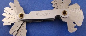
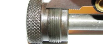
The thread gauge (Fig. 198) consists of a set of steel plates, each of which is equipped with cutouts that exactly match the thread profile of a certain pitch. Each plate is stamped with numbers indicating the thread pitch in millimeters or the number of turns cut per inch length. When measuring the pitch, apply the plate to the thread being tested parallel to its axis (Fig. 198). The coincidence of the thread gauge plate is checked for clearance.
Measuring the average thread diameter. You can accurately measure the average thread diameter with a thread micrometer (Figure 199). It differs from a micrometer for smooth parts only in that instead of permanent measuring surfaces it has special replaceable measuring tips 1 and 2. Tip 1 (Fig. 199, b), equipped with a cone with an angle equal to the angle of the thread profile, is inserted into the hole of the micrometer screw, tip 2, equipped with a slot, is placed in the heel.
When measuring, a thread micrometer is installed so that the cone fits into the recess of the thread, and the measuring tip with a cutout covers the protrusion of the thread (Fig. 199, a). The reading on the micrometer scale shows the size of the average diameter of the thread.
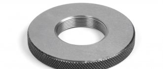
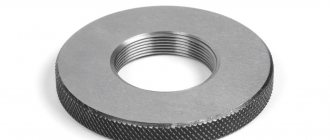
Thread gauges. The best tools for monitoring threads are thread gauges - normal and limit. The external thread is checked with a normal threaded ring (Fig. 200), and the internal thread with a normal threaded plug (Fig. 201). The right smooth end of the plug is used to check the diameter of the hole for the thread, and the left threaded end is used to check the thread itself. The correctness of the thread with normal gauges is determined by touch by the absence of wobble and the difficulty of screwing together the gauge and the part.
Checking threads using extreme thread gauges is much more accurate and productive. External threads are checked using limit thread clamps. Such a bracket (Fig. 202) has two pairs of rollers: the front pair is pass-through, and the rear pair is non-pass-through.
The method of checking threads with a limit thread clamp is the same as when checking smooth dimensions, i.e. the thread must pass freely through the bore side of the gauge, and the non-bore side of the gauge must hold up the thread.
The internal thread is checked using limit screw plugs (Fig. 203). The bore end of the plug has a long, full profile thread; it must be completely screwed into the threaded hole along its entire length. The non-go end has 2-3 turns of a cut profile; it should not be screwed into the hole being measured.
Both smooth and threaded limit gauges are usually used in the manufacture of a large number of identical parts and in general in cases where parts must have precise dimensions with certain tolerances.
Measuring the average and internal diameters of threads. Sometimes you have to measure the average diameter of a thread; in such cases, use a special caliper (Fig. 204) with replaceable ball tips. The diameter of the balls is selected according to special tables in accordance with the type and pitch of the thread. The legs of calipers with ball tips are first installed on a reference piece or thread gauge. After this, check the taken size with the average diameter of the cut thread, applying the installed calipers with ball tips to its side surfaces.
The internal diameter of the thread is measured using calipers with sharp legs (Fig. 205). As in the previous case, the calipers are first set to the size of a caliper, a standard part or a thread gauge, then this size is compared with the internal diameter of the cut thread.
The outer diameter of the bolt thread is measured with a caliper or micrometer. In this case, it is necessary to ensure that the measuring tool is installed perpendicular to the axis of the part.
09 November 2022, 11:20 1055
The instructions, to a greater extent, concern the determination of the sizes of metric bolts, screws and studs (hereinafter simply bolt). The fundamental dimensional characteristics of a bolt are diameter, thread pitch and length.
Bolt diameter
The exact diameter of a bolt, like any other object, is measured with a caliper or micrometer. However, there are situations when special measuring instruments are not at hand. In this case, you can measure the outer diameter of the bolt using a measuring tape.
Wrap the measure around the bolt shaft one turn and mark the connection point on the scale. This is how we found out the circumference of the bolt. We reduce the result by 1-2 mm to eliminate the influence of the thickness of the measure on the calculations.
Knowing the circumference, we can easily calculate the diameter using a simple geometric formula. To do this, divide the circumference by Pi, equal to 3.14. Since most car bolts have standard diameters, even taking into account errors in measurements, the result will be close to standard sizes. Standard diameters of bolts used in cars: 5, 6, 7, 8, 10, 12, 14, 16, etc.
It is fair to note that this method is not suitable for measurements where special accuracy is required. For example, the driven part of a wheel stud, where every tenth of a millimeter is important, is measured only with a caliper or micrometer.
Bolt thread pitch
Another important bolt parameter is the thread pitch. Thread pitch is the distance between two adjacent turns. The thread pitch is measured by a pedometer. However, just like a caliper, there may not be a pedometer. Then calculate the distance between the turns using a ruler
To do this, count 15-20 thread turns (the more turns, the more accurate the result) and measure the distance between the outer turns with a ruler. By dividing the length of the counted turns by the number of turns, we obtain the distance between the turns, i.e. the thread pitch.
The thread pitch of a car bolt is a standardized value and is closely related to the diameter. Knowing the bolt diameter and the calculated thread pitch, we can easily determine the exact thread pitch using the following table.
Thread inspection devices
For comprehensive control and measurement
external metric threads use rigid limit ring gauges (GOST 17763-72 and GOST 17764-72), as well as threaded clamps. Internal threads are controlled using thread plug gauges (GOST 17756-72 and GOST 17759-72). When using threaded plug gauges and rings, the pass gauge acts as a complex meter. A no-go gauge is used to measure the limiting size of the average diameter.
Ring gauge M 1.1x0.25 6h PR for complex control and measurement of external metric threads
During element-by-element inspection
the outer diameter of the bolt is checked with any instruments that are usually used to control the diameter of shafts. And the inner diameter of the nut is used for hole control.
To control the average diameter, contact and non-contact methods are used. The first is based on the use of micrometer inserts or three wires.
Measuring mean diameter with thread micrometer inserts
A thread micrometer with inserts is used to measure the average diameter of a triangular thread with profile angles of 60 and 55 degrees. The measurement is carried out in the range from 0 to 350 mm. For each 25 mm interval, either a separate micrometer or special interchangeable anvils are used.
Threaded micrometer MVM-50 GRIFF with inserts for measuring average diameter
The standard kit includes two inserts: a prismatic one, which is placed instead of the micrometer heel, and a conical one, installed in the hole of the micrometer screw.
The micrometer can be equipped with one of five sets of inserts, which are selected depending on the pitch of the thread being tested: 0.4–0.5; 0.6–0.8; 1–1.5; 1.75–2.5; 3–4.5 mm.
Monitoring the thread pitch and profile angle using indicator measuring instruments
The thread pitch and profile angle are measured using microscopes and projectors. In this case, the average diameter of the internal thread is controlled:
- indicator devices with sliding half-plugs;
- indicator devices with sliding inserts;
- horizontal optimeters using measuring arcs with ball measuring tips.
It is convenient to measure the dimensions of parts during processing using an indicator device. Thanks to the special design of the stop bar, this device allows you to install the indicator holder in a convenient place. The device is universal and can be used both for boring and turning.
Indicator device for active dimensional monitoring during lathe processing
The use of indicators and setting rings with the nominal size of the hole being machined reduces the time for preliminary operations and ensures high accuracy in measuring the internal dimensions of the thread.
When processing holes, the cutter is adjusted according to the indicator to remove the first chip with an allowance of 0.1–0.2 mm per side. After this, the indicator readings are measured, and the first chips are removed. The resulting hole size is measured with an indicator device adjusted to the setting ring with the nominal hole size. When setting up, the indicator device is set to zero.
After measuring the hole, they determine which layer of metal needs to be removed to obtain the final size of the hole. Then, according to the indicator, the cutter is installed under the boring of the finishing hole. This measurement method simplifies boring holes according to accuracy classes 2 and 3.
If the batch of parts is large, it is more convenient to first perform preliminary boring of all products with an allowance of 0.3–0.5 mm per diameter, and then complete the finishing boring in one pass with a rigid cutter. The use of indicator devices allows you to work confidently and with great accuracy. However, the indicator does not eliminate the need to use maximum calibers. Measuring the thread with a gauge is a mandatory procedure that is required for final size control.
Thread measuring instruments. Thread measuring wires.
Active control devices.
One of the most progressive control methods is active.
Its most rational use is in conditions of mass and large-scale production. Active control devices for a certain dimensional measurement allow you to automatically change the course of the technological process and ensure the specified processing accuracy. Active control devices can be turned on at the end of the processing cycle and, based on the measurement results, issue a command for sub-adjustment of the cutting tool (they are called sub-adjusters) or check the dimensions of the product directly during processing in order to regulate the amount of movement, cutting modes and other parameters of the technological process. Active control devices that regulate the parameters of technological processes are used in computer-controlled machines.
For automatic control and adjustment, contact and non-contact devices are used. For contact action devices, the tip is in contact with the product being measured and can, when triggered, cause an error in the device. To reduce this possibility, the tips of active monitoring devices are made of carbide, diamonds, agates or other particularly hard materials.
Devices for measuring threads.
The main controlling parameters of threads are the outer middle and inner diameters, profile angle and pitch. When measuring threads, complex and element-by-element control means are used.
For comprehensive control of external metric threads, rigid limit ring gauges ( GOST 17763 - 72 and GOST 17764 - 72 ) or threaded clamps are used. Internal threads are checked with thread plug gauges ( GOST 17756 - 72 and GOST 17759 - 72 ). When using threaded plug gauges and rings, the complex meter is the pass gauge. A no-go gauge is used to measure the maximum size of the average diameter.
With element-by-element inspection, the outer diameter of the bolt can be checked by any measuring instrument used to control the diameter of shafts, and the internal diameter of the nut by any measuring instrument used to control holes.
To control the average diameter, contact or non-contact methods are used. The contact control method is based on the use of micrometer inserts or three wires.
Thread micrometer inserts.
A micrometer with inserts is used to control the average diameter of triangular threads with profile angles of 60 and 55°. The measurement is made in the range from 0 to 350 mm, and for each 25 mm interval either separate micrometers or special interchangeable anvils are used. The set of inserts for the micrometer consists of two inserts (Fig. 1): a prismatic one, which is installed instead of the heel of the micrometer, and a conical one, installed in the hole of the micrometer screw.
Rice. 1. Inserts for thread micrometer.
The micrometer is equipped with five sets of inserts, which are installed in relation to the pitch of the thread being tested: 0.4 - 0.5; 0.6 - 0.8; 1 - 1.5; 1.75 - 2.5 and 3 - 4.5 mm.
Measuring threads using the three-wire method.
When checking the average diameter, a set of three wires of the same diameter is used. During the measurement process, two wires are installed in the thread recesses on one side, and the third in the opposite recess. The size of the wires is selected according to a special table depending on the pitch and angle of the thread profile. The ideal size for wires is the diameter d = tan α /2c, where cs is the pitch, and α /2 is the profile angle of the thread being tested.
Measuring the average thread diameter.
Depending on the required accuracy when measuring with wires, micrometers or optical-mechanical devices are used, which provide more accurate readings. If the axes of the wires are located vertically during measurement, then the wires are suspended on a bracket mounted on the device used (Fig. 2). Measuring surfaces are brought to the wires and the distance between the protruding points of the three wires located in the recesses of the thread is measured, then the average diameter is determined using the formulas.
Calculation of the average thread diameter.
Medium thread diameter with profile angle 60°:
Dcp = M – 3 d + 0.866 s ,
where M is the size obtained as a result of measurement, mm;
d—wire diameter, mm;
s — pitch of the measured thread, mm.
If the profile angle is 55°, then the average diameter of the cylindrical thread:
Dcp = M – 3.165 d + 0.9605 s .
Rice. 2. Measuring the thread using three wires.
Non-contact methods of thread inspection using the average thread diameter are based on three wires, the use of measuring microscopes with goniometric eyepiece heads, and also projectors.
Indicating measuring instruments.
Monitoring the accuracy of the thread pitch and measuring the profile angle is also carried out using measuring microscopes or projectors.
Control of the average diameter of the internal thread can be carried out with indicator instruments with sliding half-plugs, indicator instruments with sliding inserts, as well as on horizontal optimeters using measuring arcs for internal measurement equipped with ball measuring tips.
At most factories, when boring holes for preliminary measurements, they use plugs and punches, as well as calipers. Installation of the cutter to remove chips to the required size is carried out along the dial of the machine's transverse support based on the readings of the caliper. When machining holes according to the 2nd and 3rd accuracy classes, this generally accepted measurement method is associated with a large amount of time spent on removing test chips, and often on unnecessary passes.
You can measure the dimensions of a number of parts during processing using an indicator device (Fig. 3), which, thanks to the special design of the stop bar 1, allows you to install indicator holder 3 4 in a convenient place, in front of the transverse slide of the caliper. When feeding the transverse slide away from you, the indicator pin rests against the protrusion of bar 1. Screw 2 protects the indicator from breakage. This device is universal; it can be used both for boring and turning. For turning, the stop bar and indicator 3 are rotated 180°.
Rice. 3. Indicating device for active control of dimensions during machining on a lathe.
Practice has shown that the use of indicators and setting rings with the nominal size of the hole being machined, as well as the use of an indicator device (Fig. 3), can reduce auxiliary time and ensure high accuracy of measurements of internal dimensions.
When processing holes, it is necessary to use the indicator to adjust the cutter to remove the first chip with an allowance of 0.1 - 0.2 mm per side, note the indicator reading and remove the first chip. After this, measure the resulting hole size with an indicator device adjusted to the setting ring that has the nominal size of the hole (when adjusting, the indicator device is set to zero).
Having measured the hole, it is determined which layer of metal needs to be removed with a cutter to obtain the final size of the hole, and using the indicator, the cutter for boring the hole is set to the finishing size. This method of measurement simplifies boring holes according to the 2nd and 3rd accuracy classes, and it is quite accessible to low-skilled workers.
For large batches of parts of small mass, it is sometimes advisable to first carry out preliminary boring of the entire batch of parts with an allowance of 0.3 - 0.5 mm per diameter and then, in one pass, using a rigid cutter, carry out finishing boring.
Considering that the cutter wears out during operation, as a result of which the size of the hole decreases, during the processing of each subsequent part, you should check the actual size of the hole of the already processed part with an indicator for internal measurements and, based on the indicator readings, adjust the indicator device taking into account the wear of the cutter.
The advantage of working with an indicator is that its readings are not affected by wear on the threads of the screw and the nut of the transverse caliper, whereas the readings on the dial depend on the degree of thread wear.
It should be noted that generally accepted methods of boring holes do not provide high accuracy. When processing a hole whose diameter is smaller than the specified one, the turner does not have an exact idea of how many hundredths of a millimeter need to be additionally removed to obtain the final size. Therefore, he is often forced to resort to additional passes, which significantly increases processing time and degrades quality.
The use of indicator devices makes it possible to work confidently and with great accuracy. The use of an indicator does not exclude the use of limiting calibers. Checking the holes with the limit gauge is mandatory during the final size control.
Active control devices
One of the most progressive methods for measuring thread parameters is considered active. It is especially in demand in conditions of mass and large-scale production. Active control devices allow you to automatically monitor the progress of the technological process and provide the necessary processing accuracy.
Active control devices are usually included in the final processing cycle and, based on the results of the check, issue a command to adjust the cutting tool. There is a second way - to check the dimensions of the product during processing in order to immediately control the amount of movement, cutting conditions and other parameters. Active control devices of this type are used on machines with numerical control.
For automatic control and adjustment, contact and non-contact devices are used. In the first case, the tip of the device comes into contact with the product being measured and may cause errors. To exclude this possibility, the tips of active control devices are made of hard alloys and diamonds.
Measuring threads using the three-wire method
The three-wire method is often used to measure the average diameter of a thread. The diameter is determined by placing wires of the same size on the recesses of the threaded connections. The parameters of the resulting structure are measured with a micrometer. The final calculation results are greatly influenced by the profile error. To eliminate it, the wires are placed on the profile so that they are connected at the level where the width of the depressions is equal to the width of the protrusions.
Using the Three Wire Method to Measure Threads
In this case, the wires should be arranged as follows:
- The 1st lies on the depression on the left side;
- 2nd and 3rd on the depressions of the opposite side.
It is necessary to ensure that during measurement the part does not deform and the wires do not bend.
The size of all three wires used to measure the average thread diameter using this method is selected according to a special table, taking into account the pitch and angle of the thread profile. The ideal diameter is d = tan α /2c, where cs is the pitch, and α /2 is the profile angle of the thread being tested.
In addition to the average diameter, the diameter of the trapezoidal thread is measured using the three-wire method.
Thread Measuring Tools
Thread control is achieved in practice using a variety of measuring tools. Let's look at the most used ones.
Vernier tools and micrometric tools are measuring instruments widely used in mechanical engineering, so acquiring skills in working with them is mandatory. The main vernier tools include calipers.
The reading device in vernier tools is a linear vernier. This device allows you to count fractional parts of the interval of divisions of the main scale of the caliper tool.
The interval of division of the vernier scale a′ is less than the interval of division of the main scale a by a value c, called the vernier reading value, if the vernier module γ = 1. When the module γ = 2, the division of the vernier scale a′ is less than two divisions of the main scale, also by the size of c.
At the zero position, the zero strokes of the main scale and the vernier scale coincide. In this case, the last stroke of the vernier scale coincides with the stroke of the main scale, which determines the length l of the vernier scale. During measurement, the vernier scale is shifted relative to the main scale, and by the position of the zero line of the vernier scale, the magnitude of this shift is determined, equal to the size being measured. If the zero line of the vernier is located between the lines of the main scale, then the vernier lines that follow it also occupy an intermediate position between the lines of the main scale.
Due to the fact that the divisions of the vernier scale differ from the divisions of the main scale by the amount c, each subsequent division of the vernier is located closer to the previous one to the corresponding stroke of the main scale. The coincidence of any kth stroke of the vernier with any stroke of the main scale shows that the distance of the zero stroke of the main scale, along which whole divisions are counted, is equal to kc.
Thus, the reading of the measured quantity A on a vernier scale consists of the reading of whole divisions N on the main scale and the reading of the fractional part of the division on the vernier scale, i.e. A = N + kc.
The vernier and main scale parameters are related by the following equations:
c = a/n; c = γa - a′; l = n (γa - c); l = a (γn - 1), 7.1
where l is the length of the vernier scale; n – number of divisions of the vernier scale.
The given formulas allow you to calculate the vernier and readouts on a scale with a vernier.
Example. For the vernier shown in Fig. 7.2, a and b, determine c and take a reading if a = 1 mm.
Based on formulas (7.1), according to Figure 7.2, a we determine that n = 10, γ = 2, l = 19 mm.
Therefore c = a/n = 1/10 = 0.1 mm
According to Fig. 7.2, b we determine the readings on the main scale N = 60 mm and on the vernier scale ck = 0.1x5 = 0.5 mm. Total reading A = N + ck = 60 + 0.5 = 60.5 mm.
Usually, when calibrating the vernier scale, the reading value on the vernier scale is taken into account. So, for example, on a vernier scale with a reading value of C = 0.02 mm, the number 10 means “ten hundredths of a millimeter” and corresponds to the fifth division of the vernier, the number 20 corresponds to the tenth division of the vernier, etc.
In Fig. 7.3 shows a caliper type ShTs11 - with a double-sided arrangement of measuring jaws 1, 2, 3, 4. The upper pair of measuring jaws (1 and 2) is intended for measuring holes, the lower one is for external measurements. The upper jaws are located relative to the main scale and the vernier scale so that when measuring internal dimensions, the counting is from zero, as when measuring external dimensions. Vernier scale – 5, screw – 6 serves to fix the position of the movable jaw.
| Vernier characteristic | Zero positions | Counting examples |
| a=1mm; a′=1.9 c=0.1mm; n=10 γ=2 | 60,5 | |
| a=1mm; a′=0.98 c=0.02 mm n=50; γ=1 | 64,18 |
Rice. 7.2 Zero positions of caliper scales and examples of reading depending on the module γ
| 1 |
| 2 |
| 6 |
| 3 |
| 4 |
| 5 |
Rice. 7.3 Vernier calipers, type ШЦ11
Thread micrometer. To measure the average diameter of the external thread on a rod, use a thread micrometer (Fig. 7.4). Externally, it differs from the usual one only in the presence of measuring inserts - a conical tip inserted into the microscrew hole, and a prismatic tip placed into the heel hole. Inserts for the micrometer (Fig. 7.5) are made in pairs, each of which is designed to measure fastening threads with a profile angle of 60° and 55° and with a certain pitch. For example, one pair of inserts is used to measure threads with pitches of 1 - 1.75 mm, the other - with pitches of 1.75 - 2.5 mm, etc.
After setting the micrometer to zero, the inserts wrap around one turn of the thread being tested. As soon as the inserts come into contact with the thread surface, lock the micrometer screw and read the result on the scales of the micrometer head
| Rice. 7.4 Thread micrometer | Fig.7.5 Inserts for micrometer |
Delays. The wires are used to measure the average diameter of the thread (Fig. 7.6). To do this, they are placed in the grooves of the thread, and then using a contact device (micrometer, optimeter, etc.) the size M is determined. Using the known values of the pitch, half the angle of the thread profile and the diameter of the wires, the actual size of the average diameter of the thread is calculated. So for a metric thread (α/2 = 30о), the average thread diameter will be equal to: d2 = M – 3d + 0.866 × S, where d is the diameter of the wires, S is the thread pitch.
Rice. 7.6 Wires for measuring the average diameter of a thread
Measuring the average diameter of a thread using three wires is most commonly used. This method is used not only to measure fastening threads, but also kinematic (running) threads.
Threaded rings are rigid. To measure external cylindrical right and left threads, rigid threaded rings are used (Fig. 7.7). This is what they are called in contrast to adjustable threaded rings. The test consists of screwing together a threaded ring with the part being tested. The thread is checked with two rings: a pass ring (PR), made with a full profile thread along the entire length of the ring, and a non-go ring (NOT), which has an incomplete shortened profile thread with 2 - 3.5 turns.
The threaded ring through the thread must screw together freely with the part being tested and pass without jamming along the entire length of the thread. No-go threaded rings should not be screwed onto the part more than 3.5 turns.
To distinguish it, the no-go ring has an annular groove on the outside. All rings are marked indicating the maximum caliber (NOT, PR), size and type of thread.
Thread gauges. To measure internal cylindrical right and left threads, thread gauges (plugs, Fig. 7.8) with inserts and nozzles are used; passing (PR) and non-passing (NOT). Threads are checked and measured with screw plugs in the same way as with threaded rings.
Figure 7.7 – Rigid threaded rings
External threads with a diameter of 6 to 52 mm are sometimes controlled by threaded roller brackets of other designs. Conical internal and external, right and left threads from 1/8" to 2" are measured with special gauges.
Thread gauges. To measure the pitch of a thread, thread gauges are used - sets of templates (thin steel plates) (Fig. 7.9), the measuring part of which is a profile of a standard thread of a certain pitch or with a certain number of threads per inch to calculate the pitch.
Rice. 7.8 Thread gauges
Rice. 7.9 Thread gauges
Thread gauges are made in two types: for metric threads with pitch (in mm): 0.4; 0.45; 0.5; 0.6; 0.7; 0.75; 0.8; 1; 1.25; 1.5; 1.75; 2; 2.5; 3; 3.5; 4; 4.5; 5; 5.5; 6 and for inch and pipe threads with the number of threads (per inch): 28; 20; 19; 18; 16; 14; 12; eleven; 10; 9; 8; 7; 6; 5; 4.5; 4.
Externally, the thread gauges - templates differ in that the thread gauges for metric threads have the stamp “M60o” stamped on them, and the thread gauges for inch and pipe threads have the stamp “D55o” stamped on them.
When determining a thread from nature, by measuring individual parameters, approximate data is obtained, with the help of which, using the thread tables in the standards, its type and size are specified. The need to determine threads from nature may arise in two cases: 1) when replacing a partially worn or completely failed non-standard threaded part; 2) during installation and repair work, when for some reason the thread size is unknown, and during the work it is necessary to install a new product or assembly with a threaded connection.
The accuracy of measurement when determining threads from nature is influenced by many factors, the main ones being the following:
a) percentage of wear and contamination of the part;
b) convenience of measuring the part;
c) type, quality and cleanliness of the measuring instrument;
d) skills in using the tool, its correct installation without displacements or distortions;
e) compliance with the temperature measurement regime.
For a more accurate determination, it is recommended to take three measurements of the same size in succession and take their average value as the final result. Estimated measurement accuracy in different cases can range from 0.5 to 0.25 mm.
Since in production, and even more so in educational practice, a thread gauge is most often used when making sketches from life, let’s consider how this measurement is performed.
To measure the thread pitch, a template is selected with a thread gauge - a plate, the teeth of which coincide with the cavities of the thread being measured (Fig. 7.10). Then read the pitch (or number of threads per inch) indicated on the plate. When determining the pitch using an inch thread gauge, divide the inch (25.4 mm) by the number of threads indicated on the template. The outer diameter of the thread d on the rod or the internal diameter of the thread D1 in the hole is measured in the usual way with a vernier caliper (Fig. 7.11) (placing the measuring jaws of the caliper in axial diametral plane) from the end of the rod or hole. Having these initial data, the exact thread value is selected using tables of standard threads.
In the absence of a thread gauge, the thread pitch (or number of threads per inch) can be determined using an imprint on paper. To do this, the threaded part of the part is crimped with a piece of clean paper in order to obtain impressions (prints) of the threads on it, i.e. several steps (preferably at least 10) (Fig. 7.12). Then, using the print, measure the distance L between the extreme, fairly clear marks. Having counted the number of steps n over a length L (it must be remembered that n is one less than the number of notches, since the average estimate of the pitch size of a given thread is determined not from the number of notches, but from the distance between them), we determine the pitch.
Rice. 7.10 Measuring the thread pitch template - with a plate
Example: the impression produced 10 clear marks (i.e. 9 steps) with a total length of 13.5 mm. The outer diameter of the thread when measured is 14 mm. We determine the pitch: P = 13.5: 9 = 1.5 mm. According to the table of standard threads in the GOST 8724 - 81 standard, we find the thread: M14 ´ 1.5, i.e. metric thread of the 2nd row with a diameter of 14 mm and a fine pitch of 1.5 mm.
In holes, thread determination by this method is possible only with sufficiently large diameters. In general, the threads of holes should be measured on those parts that are screwed into a given hole.
| Rice. 7.11 Measuring the internal diameter of thread d1 with a caliper | Rice. 7.12 Thread impressions |
In practice, determining a thread using the described method is facilitated by the fact that for the most common diameters, metric thread pitches are expressed either as an integer number of millimeters, or as a multiple of 0.5 mm or 0.25 mm.
Metric thread diameters, starting from 6 mm, are always measured in whole numbers of millimeters.
For inch threads, the diameter and pitch can be expressed with sufficient approximation only in thousandths of a millimeter, but the number of threads per inch is always an integer.
When measuring metric and inch threads, it may turn out that the comb templates do not fit between the thread turns of a particular product, and the measured diameter (external or internal), even with a rough estimate of wear, does not correspond to the dimensions established by the standard. Such a discrepancy between the pitch and diameter of the standard indicates that the thread of this product is non-standard. In this case, the drawing must indicate the thread pitch P, measured by the above or another method with sufficient accuracy, the outer and inner diameters common to the bolt and nut.
When measuring one thread diameter (external or internal), the other can be determined by counting. As is known, the dimension H - the radially measured height of the main design profile, common to the bolt and nut, can be expressed in terms of a step P, as through a module.
For metric thread: H = 0.86603 R.
For inch: H = 0.6403 P
The diameter d1 for the rod is determined by the formula:
d1 = d – 2x0.86603 P - for metric threads,
d1 = d – 2x0.6403 Р – for inch thread.
In the same way, you can determine the necessary parameters for special lead screws: trapezoidal, thrust, round and rectangular profile.
Thread pitch measurement
To measure the thread pitch, use a caliper or ruler. To do this, determine the length of several steps and divide it by the number of steps. The pitch of internal and external threads is determined by a thread gauge. Each plate indicates the step size. In this case, the plates are selected so that the teeth fit tightly into the thread. Thanks to this, the pitch coincides with the pitch on the plate.
To measure the thread pitch, standard rulers with millimeter and inch graduations and thread gauges are used. The results of calculating the pitch with a ruler are inaccurate, so the main task when taking measurements is to find the number of turns that fall on a single thread pitch. Let's say if there are 5 turns per 1 inch, the pitch will be 1/5 inch. For convenience, results in inches are converted to millimeters.
To measure the thread pitch correctly, you need to be aware of the following tricks:
- you should measure not individual sections, but the entire part of the part profile;
- before measurement it is necessary to count the whole number of turns;
- The thread pitch is determined after measuring the depth and basic parameters of the threaded connection.
The result of the measurements will be the average step value. The error in the calculations depends on how correctly the thread is cut on the part.
The thread gauge provides the most accurate pitch measurements for pipe and tapered threads because it works with the tightest distances. The design includes plates made of iron alloys. Each plate has cutouts equal to the cutting profile and its pitch.
To determine the pitch size, a thread gauge is applied to the part. In this case, it is necessary to ensure that the plate is parallel to the cutting axis and matches the size of the thread hole.
Thread measurement methods
Measuring threads primarily involves measuring diameters, pitches and surface shapes. For this purpose, both special and universal tools are used. The required measuring device is selected depending on the type of thread, as well as its accuracy. First, the average diameter, pitch, and profile shape are controlled, after which the internal and external diameters are checked.
Thread pitch measurement
The pitch is determined using a caliper or ruler. In this case, the length of several steps is determined and divided by the number of steps. The pitch on the internal and external threads is determined using a thread gauge. Each plate indicates the step size. The plates are selected so that the teeth fit tightly into the thread. This allows the pitch to match the pitch on the plate.
Average diameter
Measurements of the average thread diameter are carried out using a thread micrometer. It is important to use different sets of tips (one with a cone and one with a cutout) of the required size. The application limit is indicated on the measuring instruments themselves. For example, marking M 3-5 means that the kit allows you to measure parts with a thread pitch of 3; 3.5; 4; 4,5,5 mm.
Thread profile
The measurement of threads along profiles is carried out with a special microscope and is controlled by the profiles. A normal threaded ring measures the outer diameter of the thread. A ring is screwed onto the screw, which shows the accuracy of the thread by shaking. The internal diameter is coordinated using a standard threaded plug. Its protruding smooth end also serves as a tool for controlling the diameter of the threaded hole.
Checking with thread gauges
Thread gauges are used to check the accuracy of threaded connections. The internal thread is measured using a special plug, the male end of which must fit into the threaded hole for the entire length. The no-go end includes 2-3 turns of the profile; it is not screwed into the hole. The external threads are controlled by rings that are screwed onto the screw and clamped with an adjustable clamp.
Checking with CMM
An inspection and measuring machine is an unsurpassed tool for measuring parts in production. This is a specially designed unit that allows you to scan the surfaces of parts and transmit coordinates to the control unit using a probe. Measurements using CMM can be carried out in six axes. In instrument making, a measuring machine with six axes developed by the specialists of Lapik LLC is in demand.
Measuring the average diameter of a thread
To measure the average diameter of a thread, you must use a thread micrometer complete with different tips (one with a cone, the other with a cutout). The measurement limit is usually indicated on the measuring instruments themselves. Thus, the marking M 3–5 means that the kit allows you to measure threads in increments of 3; 3.5; 4; 4.5 and 5 mm.
Inserts for thread micrometer
A micrometer is used to measure the average thread diameter. Replaceable tool tips are inserted into the screw hole and allow for the most accurate measurements.
If averaged values are sufficient as a result, calipers can be used instead of a micrometer. By design, it consists of ball tips, the dimensions of which must match the type and pitch of the threaded connection. To find out the average diameter, the tips of the calipers must be aligned with the thread gauge. Then the procedure is repeated with the sides of the part. Threaded clamps are used to evaluate measurement results. And the accuracy of the diameter is checked by comparing the resulting thread with the template.
To control the average diameter of a thread consisting of a maximum of two turns, use the two-wire method. The measurement is carried out as follows: wires, the diameter of which coincides with one of the tabular units, are placed on the opposite protrusions and recesses of the thread. In this case, the distance between the ends of the wires shows the average diameter of the part. For each accuracy class, separate wires are created that comply with GOST 2475-88. When deriving final numbers, possible errors are taken into account, because the two-delay method does not allow achieving accurate values.
Another method for measuring the average thread diameter is to use a microscope. The device is applied to the side of the workpiece profile, and the eyepieces are pointed at the profile image on each side to determine its size. The values obtained as a result of measurements are added and divided by the number of sides. The resulting arithmetic mean is the average diameter of the threaded connection.
Average diameter of threaded connection
To determine the average diameter of a thread, you need a micrometer with special tips in the form of a cone and a cutout. It is used to determine the size of the part at the top of the thread and at the root to calculate the average value. When selecting a kit, it is necessary to take into account the measurement limit, which is indicated in the marking with the letter M and numbers indicating the minimum and maximum allowable thread pitch. Also, to obtain the average thread value, calipers with ball tips are used, the profile of which matches the type and pitch of the thread. The tips are calibrated on several sides of the part for the most accurate result.
Measuring the outer diameter of a thread
To measure external threads, micrometric instruments are used, the basis of which are microscrews. Control is carried out according to this scheme.
- Microscrews are applied to the thread profile. The position of the instrument is adjusted by rotating the micrometer several times.
- Record the size of the cutting profile for one side. The value is calculated based on the division value on the microscrew scale.
- The micrometer is applied to the opposite end of the profile and its size is calculated.
- The result of measuring the outer diameter of the thread is determined by subtracting the result of the second from the result of the first calculation.
Measuring with a thread gauge
The best option for correctly measuring threads is to use a thread gauge. This is a special tool for measuring cutting pitch. The thread gauge is a body to which probes are attached in the form of thin plates with a comb. The shape of the comb exactly matches the standard thread with a certain pitch.
The following types of thread gauges are distinguished:
- Metric. Allows you to measure the thread pitch of a bolt, nut or other part with a metric thread with a diameter from 1 to 600 mm. The tool has up to 20 measuring plates and allows you to determine thread pitch from 0.4 mm to 7 mm. Indicated by the marking “M60” on the body.
- Inch. Used to measure inch threads, which are usually cut on pipes and pipeline parts, and are also sometimes used on fasteners. The pitch of an inch thread is determined by the number of threads per inch of length of the threaded part of the part. The thread gauge is equipped with 17 measuring plates with a number of turns from 4 to 28. The “D55” marking is used to mark the tool.
- Universal. Equipped with measuring plates for metric and inch cutting. Such thread gauges are widely used in workshops where it is necessary to simultaneously work with parts with both metric and inch threads.
Before determining the pitch, you need to measure the diameter of the thread with a caliper. This is necessary because the pitch range may depend on the diameter.
The process of measuring pitch using a thread gauge is extremely simple. Visually suitable thread gauge plates are applied to the thread being measured. Using the selection method, a plate is selected whose comb will exactly match the thread being measured. Its pitch will correspond to the standard value indicated on the marking of the measuring plate.
The easiest way to measure external threads is this way. If you need to determine the pitch of the internal thread, then the measurement location must be illuminated in order to accurately determine the tight fit of the thread gauge plate comb.
When measuring the pitch of a metric thread, the desired parameter is obtained in millimeters. If it is necessary to measure the pitch of an inch thread, then its value is obtained in the number of turns per inch.
Measuring the internal diameter of a thread
The internal thread is measured using calipers. The tool is installed on a template part using a thread gauge, and then compared with the original internal diameter of the threaded connection. To obtain accurate values, the caliper must be positioned at an angle to the axis being measured.
You can also use cylindrical thread gauges to measure the internal diameter of a thread. This is because the inner diameter has a smooth surface and is ideal for the shape of the tips used in these instruments. The results obtained are checked using plug gauges.
Caliber
Unlike a micrometer, calipers and other instruments, for each diameter, type and thread pitch there is its own separate gauge, which is the standard of the maximum permissible value. To match the thread to the gauge, it is necessary that the latter can be screwed freely without any effort or gaps along the entire length. There are nut gauges and plug gauges for external and internal threads, respectively. The advantage of this method is the simplicity and accuracy of measurement. The main disadvantage is the need to use a set of gauges when checking more than one type and diameter of threaded connections.
Thread profile measurement
To measure the thread profile, a tool such as a microscope is used, and control is carried out using profiles. The procedure is carried out in the following sequence.
- A normal threaded ring measures the outer diameter.
- A ring is put on the screw, which demonstrates the accuracy of the thread by shaking.
- The diameter is coordinated using a standard threaded plug. At the same time, its protruding smooth end simultaneously serves as a tool for controlling the diameter of the threaded hole.
Measuring thread pitch without a thread gauge
Parts with external thread
Often the need to determine the thread pitch arises sporadically, at one time. And, of course, in such a situation there is no thread gauge at hand, and it makes no sense to buy one for one-time measurements. It will be useful to learn how to measure the thread pitch with a ruler or caliper. These measuring tools make it quite easy to determine the desired parameter.
The easiest way is to measure the threads of a bolt or other externally threaded part. When measuring a metric thread, it is recommended that you first attach the ruler to the threaded part and try to align the millimeter divisions of its scale with the tops of the ridges of the threaded profile. If they coincide, then the step is 1 mm. Otherwise, you will have to carry out slightly more complex measurements.
To determine the thread pitch, you need to count the number of turns on a section of a rod of a certain length, for example, 10 mm or 20 mm. To obtain a more accurate result, it is recommended to take measurements on a 20 mm area. The required length is measured by applying a ruler to the bolt shaft, or using a caliper. It would be more accurate to measure the bolt thread pitch with a caliper. In the measured area, count the number of turns. After this, the length of the section must be divided by the resulting number of turns minus one turn. As a result, we obtain the value of the thread pitch.
When determining the pitch of an inch cutting, it is necessary to measure the length of the rod equal to one inch (25.4 mm). For accurate measurements, it is better to use a ruler or caliper with an inch scale. The number of turns in this area will be the thread pitch. If the length of the threaded section is less than one inch, then you need to determine the number of turns in a section of half an inch (12.7 mm), and then multiply the result by 2.
Internally threaded parts
There are two ways to measure the thread of a nut or other internally threaded part without a thread gauge. The first method involves selecting an exactly suitable counter bolt and then measuring its thread pitch. If you can’t find the counter bolt, then you need to use a strip of paper (this is method No. 2).
It should be pressed against the thread so that an imprint of the profile remains on the paper. You can improve the visibility of marks by tracing the edges with a marker. After this, on paper you need to mark the distance between the extreme marks with a ruler and count the number of turns. Then the resulting distance is divided by the number of turns minus one turn. Instead of measuring paper using this method, you can use a pencil, match or other soft wood product of a suitable size, which is pressed against the thread.
Where to buy thread measuring tools?
You can buy the necessary tools for measuring threads in the Rincom online store. Always in stock:
- calipers;
- probes;
- micrometers;
- calibers.
You can place an order with delivery throughout Russia directly on the website. It is possible to manufacture measuring instruments according to your drawings. The batch size of products is not limited. I
