What defects can be detected during inspection?
Inspection of threaded surfaces allows you to identify the following connection defects.
Torn cuts
. A defect occurs if the diameters of the hole and rod differ from the nominal ones. The reason may also be insufficient sharpness of the cutting tool. The problem can be prevented by careful control of all diameters and the use of cutting tools of a normal degree of sharpening.
Dull cut
. The defect appears if the nominal diameter is smaller than the hole diameter, but larger than the rod diameter. When cutting, the profile becomes incomplete. Precise measurement of diameters before cutting threads will allow you to avoid defects.
Thread taper.
The defect appears when the cutting tool cuts off excess metal. The problem is solved by correlating the established dimensions of the part and the tool.
Tight cutting
. If the dimensions of the part are not respected, and the tool has a rough thread, cutting occurs with difficulty. The defect can be prevented by first measuring the parameters of the workpiece and selecting the optimal size cutting tool.
Trapezoidal
Threaded connections of this type most often include screw-nut type connections. Trapezoidal threads are made in accordance with GOST 9481-81. Its shape is an isosceles trapezoid. The angle of inclination of the edges is 30°. For the threads of fasteners used in worm gears, an inclination angle of 40° is provided.
The trapezoidal thread profile allows for increased connection strength. Due to this, it is used to connect parts of mechanisms that operate under the influence of dynamic loads, for example, in running nuts that secure valve stems, etc.
Thread inspection devices
For comprehensive control and measurement
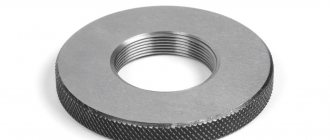
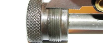
external metric threads use rigid limit ring gauges (GOST 17763-72 and GOST 17764-72), as well as threaded clamps. Internal threads are controlled using thread plug gauges (GOST 17756-72 and GOST 17759-72). When using threaded plug gauges and rings, the pass gauge acts as a complex meter. A no-go gauge is used to measure the limiting size of the average diameter.
Ring gauge M 1.1x0.25 6h PR for complex control and measurement of external metric threads
During element-by-element inspection
the outer diameter of the bolt is checked with any instruments that are usually used to control the diameter of shafts. And the inner diameter of the nut is used for hole control.
To control the average diameter, contact and non-contact methods are used. The first is based on the use of micrometer inserts or three wires.
Measuring mean diameter with thread micrometer inserts
A thread micrometer with inserts is used to measure the average diameter of a triangular thread with profile angles of 60 and 55 degrees. The measurement is carried out in the range from 0 to 350 mm. For each 25 mm interval, either a separate micrometer or special interchangeable anvils are used.
Threaded micrometer MVM-50 GRIFF with inserts for measuring average diameter
The standard kit includes two inserts: a prismatic one, which is placed instead of the micrometer heel, and a conical one, installed in the hole of the micrometer screw.
The micrometer can be equipped with one of five sets of inserts, which are selected depending on the pitch of the thread being tested: 0.4–0.5; 0.6–0.8; 1–1.5; 1.75–2.5; 3–4.5 mm.
Monitoring the thread pitch and profile angle using indicator measuring instruments
The thread pitch and profile angle are measured using microscopes and projectors. In this case, the average diameter of the internal thread is controlled:
- indicator devices with sliding half-plugs;
- indicator devices with sliding inserts;
- horizontal optimeters using measuring arcs with ball measuring tips.
It is convenient to measure the dimensions of parts during processing using an indicator device. Thanks to the special design of the stop bar, this device allows you to install the indicator holder in a convenient place. The device is universal and can be used both for boring and turning.
Indicator device for active dimensional monitoring during lathe processing
The use of indicators and setting rings with the nominal size of the hole being machined reduces the time for preliminary operations and ensures high accuracy in measuring the internal dimensions of the thread.
When processing holes, the cutter is adjusted according to the indicator to remove the first chip with an allowance of 0.1–0.2 mm per side. After this, the indicator readings are measured, and the first chips are removed. The resulting hole size is measured with an indicator device adjusted to the setting ring with the nominal hole size. When setting up, the indicator device is set to zero.
After measuring the hole, they determine which layer of metal needs to be removed to obtain the final size of the hole. Then, according to the indicator, the cutter is installed under the boring of the finishing hole. This measurement method simplifies boring holes according to accuracy classes 2 and 3.
If the batch of parts is large, it is more convenient to first perform preliminary boring of all products with an allowance of 0.3–0.5 mm per diameter, and then complete the finishing boring in one pass with a rigid cutter. The use of indicator devices allows you to work confidently and with great accuracy. However, the indicator does not eliminate the need to use maximum calibers. Measuring the thread with a gauge is a mandatory procedure that is required for final size control.
Checking accuracy and deviations
In the process of assembling and repairing mechanisms and structures, an important step is checking gaps, the accuracy of the relative position of parts and assemblies, and aligning the axes relative to each other. For these purposes, the following measuring instruments are used:
Straight lines. They are used to determine deviations in the flatness and straightness of the surface of parts. They are divided into patterned triangular, patterned tetrahedral and with double-sided bevels.
Verification prisms. They are used for marking, positioning and alignment of axes or shafts of mechanisms, as well as for monitoring the parallelism and verticality of parts. In addition, they are used for fastening parts during machining.
Goniometers. A measuring tool used to check the accuracy of angles. Mechanical models are equipped with a vernier scale for accurate measurement of deviations.
Radius and threaded templates. They are a set of plates of a certain shape, designed to determine, respectively, the radius of curvature of a part or the thread pitch by application to the controlled surfaces. Radius templates are available in concave and convex shapes.
The first are used to determine the outer radius, convex - for internal holes. Thread templates allow you to determine the pitch of a metric thread or the number of threads per inch for an inch thread.
Probes. Sets of measuring plates with a thickness of 0.02 to 1 mm for determining the gaps between mating surfaces. The size of the gap is determined by gradually increasing the thickness of the inserted probes until the maximum is reached.
Surface roughness samples. Supplied as a kit for determining the roughness parameters of metal parts, the quality of surfaces in hard-to-reach places and monitoring during the production process.
To obtain the most accurate values, you must strictly adhere to the operating instructions for the instrument - do not use excessive force, clean it from dirt, store it in a case, protect it from mechanical shock and fulfill other requirements.
Active control devices
One of the most progressive methods for measuring thread parameters is considered active. It is especially in demand in conditions of mass and large-scale production. Active control devices allow you to automatically monitor the progress of the technological process and provide the necessary processing accuracy.
Active control devices are usually included in the final processing cycle and, based on the results of the check, issue a command to adjust the cutting tool. There is a second way - to check the dimensions of the product during processing in order to immediately control the amount of movement, cutting conditions and other parameters. Active control devices of this type are used on machines with numerical control.
For automatic control and adjustment, contact and non-contact devices are used. In the first case, the tip of the device comes into contact with the product being measured and may cause errors. To exclude this possibility, the tips of active control devices are made of hard alloys and diamonds.
Thread rolling die - brief description
Today, the leading place in this type of work is occupied by the die; the die was once also a separate, frequently used tool. But recently, these two tools have been combined, and everything is called in one word - die. In appearance, they resemble hardened nuts, where there are axial holes, they also form sharp cutting edges. Typically, almost all devices have chip holes in the amount of 3 to 6. They are necessary to divert chips to the side.
Standard dies have a thickness of 8 to 10 turns. The main cutting part is always made in the form of an internal cone. The intake part has 2 to 3 turns. To make this device, durable alloy steel grade 9 XC is used, but sometimes they are made from other types of steel. Each tool has a marking and its own designation
When purchasing, you need to pay attention to indicate the degree of accuracy that will be used when cutting threads
Types of dies are divided depending on several indicators. The main criterion is the design; based on this feature, they can be single-piece (it’s not hard to guess their appearance), split and sliding (in other words, clamp-type). According to their geometric shape, the dies can be round (these are lerks), square, hexagonal, or prismatic. There are also wooden dies, but these are not a cutting tool, but simply a cut from a tree trunk, a kind of round block, sometimes they even have medicinal properties. Naturally, we will not talk about them here. And for a broader understanding of the features of all models of the instrument described above, let’s say a few words about each of them.
Measuring threads using the three-wire method
The three-wire method is often used to measure the average diameter of a thread. The diameter is determined by placing wires of the same size on the recesses of the threaded connections. The parameters of the resulting structure are measured with a micrometer. The final calculation results are greatly influenced by the profile error. To eliminate it, the wires are placed on the profile so that they are connected at the level where the width of the depressions is equal to the width of the protrusions.
Using the Three Wire Method to Measure Threads
In this case, the wires should be arranged as follows:
- The 1st lies on the depression on the left side;
- 2nd and 3rd on the depressions of the opposite side.
It is necessary to ensure that during measurement the part does not deform and the wires do not bend.
The size of all three wires used to measure the average thread diameter using this method is selected according to a special table, taking into account the pitch and angle of the thread profile. The ideal diameter is d = tan α /2c, where cs is the pitch, and α /2 is the profile angle of the thread being tested.
In addition to the average diameter, the diameter of the trapezoidal thread is measured using the three-wire method.
Pipe
>
They form the basis of the vast majority of sanitary installations and communication lines
Please note how the thread pitch of this type is measured - usually in inches, because calculations are performed using formulas from the English system of measures. The main indicator is the cross section of the nominal diameter
Helix parameters
| P, mm | Number of threads per 1 ʺ | d (outer), mm | DN, ʺ |
| 0,907 | 28 | 9,729 | 1/8 |
| 1,337 | 19 | 13,158 | 1/4 |
| 1,337 | 19 | 16,663 | 3/8 |
| 1,814 | 14 | 20,956 | 1/2 |
| 1,814 | 14 | 22,912 | 5/8 |
| 1,814 | 14 | 26,442 | 3/4 |
| 1,814 | 14 | 30,202 | 7/8 |
| 2,309 | 11 | 33,250 | 1 |
| 2,309 | 11 | 37,898 | 1 1/8 |
| 2,309 | 11 | 41,912 | 1 1/4 |
| 2,309 | 11 | 44,325 | 1 3/8 |
| 2,309 | 11 | 47,805 | 1 1/2 |
| 2,309 | 11 | 53,748 | 1 3/4 |
| 2,309 | 11 | 59,616 | 2 |
The tables provided will be your assistants - they contain the data that you can safely rely on when choosing standard values for applying turns to fastener rods.
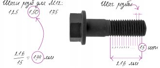
Thread pitch measurement
To measure the thread pitch, use a caliper or ruler. To do this, determine the length of several steps and divide it by the number of steps. The pitch of internal and external threads is determined by a thread gauge. Each plate indicates the step size. In this case, the plates are selected so that the teeth fit tightly into the thread. Thanks to this, the pitch coincides with the pitch on the plate.
To measure the thread pitch, standard rulers with millimeter and inch graduations and thread gauges are used. The results of calculating the pitch with a ruler are inaccurate, so the main task when taking measurements is to find the number of turns that fall on a single thread pitch. Let's say if there are 5 turns per 1 inch, the pitch will be 1/5 inch. For convenience, results in inches are converted to millimeters.
To measure the thread pitch correctly, you need to be aware of the following tricks:
- you should measure not individual sections, but the entire part of the part profile;
- before measurement it is necessary to count the whole number of turns;
- The thread pitch is determined after measuring the depth and basic parameters of the threaded connection.
The result of the measurements will be the average step value. The error in the calculations depends on how correctly the thread is cut on the part.
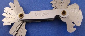
The thread gauge provides the most accurate pitch measurements for pipe and tapered threads because it works with the tightest distances. The design includes plates made of iron alloys. Each plate has cutouts equal to the cutting profile and its pitch.
To determine the pitch size, a thread gauge is applied to the part. In this case, it is necessary to ensure that the plate is parallel to the cutting axis and matches the size of the thread hole.
Recommendations for working with thread gauges
When using thread gauges, you need to take into account some features.
These features are as follows: It is recommended to store the device in sealed boxes or containers to prevent mechanical stress and deformation of the instrument. Highly accurate measurement results can be obtained using only a special tool, and you should use a ruler, caliper and micrometer in exceptional cases when you have at hand there is no specialized device When identifying threads, it is necessary to ensure that the workpiece remains stationary
Otherwise, this will negatively affect the quality of the measurements taken. Thread gauges have sharp edges, so it is important to observe safety precautions during operation. If the probes of the device have external defects, then such an instrument cannot be used for accurate measurements. Defects in the form of scratches, chips, dents, etc. will negatively affect the accuracy of the calculations performed.
On sale you can find not only metal, but also plastic thread gauges. As a rule, the body is made of plastic, and the probes are made exclusively from special grades of steel. Devices with a plastic body have a significant drawback - low strength, but at the same time they cost no more than 100 rubles.
In conclusion, it should be summarized and noted that determining the thread pitch of bolts, nuts and other fasteners is not particularly difficult if you know the algorithm and own a special tool. The obtained values after using a thread gauge allow the production of a second fastener to ensure a strong and removable connection.
Measuring the average diameter of a thread
To measure the average diameter of a thread, you must use a thread micrometer complete with different tips (one with a cone, the other with a cutout). The measurement limit is usually indicated on the measuring instruments themselves. Thus, the marking M 3–5 means that the kit allows you to measure threads in increments of 3; 3.5; 4; 4.5 and 5 mm.
Inserts for thread micrometer
A micrometer is used to measure the average thread diameter. Replaceable tool tips are inserted into the screw hole and allow for the most accurate measurements.
If averaged values are sufficient as a result, calipers can be used instead of a micrometer. By design, it consists of ball tips, the dimensions of which must match the type and pitch of the threaded connection. To find out the average diameter, the tips of the calipers must be aligned with the thread gauge. Then the procedure is repeated with the sides of the part. Threaded clamps are used to evaluate measurement results. And the accuracy of the diameter is checked by comparing the resulting thread with the template.
To control the average diameter of a thread consisting of a maximum of two turns, use the two-wire method. The measurement is carried out as follows: wires, the diameter of which coincides with one of the tabular units, are placed on the opposite protrusions and recesses of the thread. In this case, the distance between the ends of the wires shows the average diameter of the part. For each accuracy class, separate wires are created that comply with GOST 2475-88. When deriving final numbers, possible errors are taken into account, because the two-delay method does not allow achieving accurate values.
Another method for measuring the average thread diameter is to use a microscope. The device is applied to the side of the workpiece profile, and the eyepieces are pointed at the profile image on each side to determine its size. The values obtained as a result of measurements are added and divided by the number of sides. The resulting arithmetic mean is the average diameter of the threaded connection.
Instrumental measuring microscope
Two models of instrumental microscopes are used: BMI and MMI. Both of them are created according to the same concept and differ from each other, primarily in overall dimensions, a set of accessories and measurement limits. The devices allow you to measure all the main elements of the external thread profile, thread gauges, taps, various cutters and other tools. By measuring in polar or rectangular coordinates, microscopes also check the force of a threaded connection, the dimensions and contour of gauges and parts of complex shapes, shaped cutters, shaped cutters, shaped parts of dies and molds, templates, etc. All measurements on a microscope are performed using a non-contact method.
Measuring the outer diameter of a thread
To measure external threads, micrometric instruments are used, the basis of which are microscrews. Control is carried out according to this scheme.
- Microscrews are applied to the thread profile. The position of the instrument is adjusted by rotating the micrometer several times.
- Record the size of the cutting profile for one side. The value is calculated based on the division value on the microscrew scale.
- The micrometer is applied to the opposite end of the profile and its size is calculated.
- The result of measuring the outer diameter of the thread is determined by subtracting the result of the second from the result of the first calculation.
Meters used in metalworking
The most common universal measuring instrument is a ruler. The marking ruler is used by all specialists, regardless of their profile. A more specific set of measuring devices include straight edges. They are used to identify deviations of products along the plane. The magnitude of deviations is determined using calibrated probes - metal plates, the thickness of which ranges from 0.01 mm to several mm. Using special rulers, modelers determine the shrinkage size of hot ingots.
In the metalworking industry, two main types of instruments are used to measure linear characteristics:
- line instrument with vernier;
- screw type micrometer instrument.
Measuring the internal diameter of a thread
The internal thread is measured using calipers. The tool is installed on a template part using a thread gauge, and then compared with the original internal diameter of the threaded connection. To obtain accurate values, the caliper must be positioned at an angle to the axis being measured.
You can also use cylindrical thread gauges to measure the internal diameter of a thread. This is because the inner diameter has a smooth surface and is ideal for the shape of the tips used in these instruments. The results obtained are checked using plug gauges.
Types of styli
Skip menu navigation
Renishaw's extensive range of styli includes a range of configurations to suit a wide range of measurement needs.
M2 STY D2R L20 EWL14 D1.4SS
Explanation
Straight stylus with M2 thread, ruby ball with a diameter of 2 mm, length: 20 mm, effective working length (EWL): 14 mm, stainless steel rod with a diameter of 1.4 mm.
Thread profile measurement
To measure the thread profile, a tool such as a microscope is used, and control is carried out using profiles. The procedure is carried out in the following sequence.
- A normal threaded ring measures the outer diameter.
- A ring is put on the screw, which demonstrates the accuracy of the thread by shaking.
- The diameter is coordinated using a standard threaded plug. At the same time, its protruding smooth end simultaneously serves as a tool for controlling the diameter of the threaded hole.
Existing types of template thread gauges
Metric samples
Usually they have a designation on their working part in the form of the inscription “M60”, which means the value of the degrees to the metric cutting profile. The process of using this device is quite simple - you just need to sort through the available templates and select the one that will best fit into the groove according to the depth of the groove being measured on the part. Next, all that remains is to count the markings that are applied to the appropriate template. You can also combine the use of a template with a caliper and ultimately obtain more complete information about the characteristics of the screw thread being measured. It is worth noting that the parameters of the thread used must always be already fixed by state standards - otherwise, the applied thread will be considered defective.
Inch samples
They are used to measure the characteristics of inch and pipe screw joints. Using these tools, it is precisely the number of turns along the length of a certain unit of distance that is measured. The body of such thread gauges is marked “D55”, which means that the angular degree of profile pipe/inch threads is 55.
Where to buy thread measuring tools?
You can buy the necessary tools for measuring threads in the Rincom online store. Always in stock:
- calipers;
- probes;
- micrometers;
- calibers.
You can place an order with delivery throughout Russia directly on the website. It is possible to manufacture measuring instruments according to your drawings. The batch size of products is not limited. I
Persistent
They have two important design features:
- The angle width at the virtual vertex is 55 degrees.
- One side of the thread runs perpendicular to the rod, the other is inclined to prevent self-unscrewing.
Deciding how to measure the pitch of a thread of this type often falls to designers of precision instruments that accurately align the nut in relation to the bolt.
Helix parameters
| P, mm | d, mm | ||
| version | 1 row (recommended) | Row 2 (permissible) | |
| large | small | ||
| 1 | 2 | ||
| 3,00 | 2,00 | 10 | |
| 3,00 | 2,00 | 1,00 | 12 |
| 4,00 | 2,00 | 14 | |
| 4,00 | 2,00 | 1,00 | 16 |
| 4,00 | 3,00 | 18 | |
| 4,00 | 3,00 | 2,00 | 20 |
| 5,00 | 4,00 | 22 | |
| 8,00 | 5,00 | 4,00 | 24 |
| 8,00 | 5,00 | 26 | |
| 10,00 | 8,00 | 4,00 | 28 |
| 10,00 | 8,00 | 30 | |
| 12,00 | 10,00 | 8,00 | 32 |
| 12,00 | 34 | ||
| 12,00 | 10,00 | 8,00 | 36 |
| 12,00 | 7,00 | 5,00 | 38 |
| 12,00 | 10,00 | 8,00 | 40 |
| 10,00 | 8,00 | 42 | |
| 12,00 | 7,00 | 3,00 | 44 |
| 12,00 | 8,00 | 3,00 | 46 |
| 12,00 | 8,00 | 3,00 | 48 |
| 12,00 | 8,00 | 5,00 | 50 |
| 14,00 | 10,00 | 8,00 | 52 |
| 14,00 | 10,00 | 55 | |
| 16,00 | 12,00 | 10,00 | 60 |
| 16,00 | 12,00 | 65 | |
| 16,00 | 12,00 | 10,00 | 70 |
| 16,00 | 10,00 | 8,00 | 75 |
Materials
Various materials are used to produce taps, including:
- Alloy steel;
- Tool steel;
- High speed steel.
The most common and optimal option is considered to be high-speed steel. It has many advantages over others:
- High service life;
- Resistance to temperature changes;
- High quality of work performed;
- Ability to work at high speed;
- High strength material.
To work with some materials, special taps with an additional coating are made. This solution increases the service life and efficiency of the tool.
Choosing a protractor or what you need to know before buying
Based on the above description, you can make an appropriate decision about which type of tool is preferable to buy. Often the choice falls on mechanical or digital devices, followed by laser ones, and pendulum and optical devices are the least popular among home craftsmen. To choose the right meter, you need to consider the following criteria:
- The material of manufacture can be plastic, aluminum or steel. You should choose aluminum devices as a last resort, since they have a short service life
- The quality of the scale and the performance of the instrument as a whole - we visually determine how high quality this device is. If it was assembled not at the factory, but in a basement in a hurry, then this will be clearly visible. You should not choose such models
- Price - a good device will cost accordingly. If it is a mechanical instrument made of plastic, then you can buy it for 500-600 rubles; with a vernier, devices made of steel cost at least 1,500 rubles, and the most expensive ones are electronic and laser meters
To summarize, it should be noted that the type of measuring instrument in question should be in the arsenal of every master. With its help, you can not only measure the angle between two perpendicular surfaces or a specific part, but also produce high-precision workpieces and mechanisms.
Publications on the topic
How to use a small tool and features of a protractor
Torque screwdrivers and their purpose
Types of building regulations: recommendations for their application
How to repair a laser level yourself or how much does repair cost?