What defects can be detected during inspection?
Inspection of threaded surfaces allows you to identify the following connection defects.
Torn cuts
. A defect occurs if the diameters of the hole and rod differ from the nominal ones. The reason may also be insufficient sharpness of the cutting tool. The problem can be prevented by careful control of all diameters and the use of cutting tools of a normal degree of sharpening.
Dull cut
. The defect appears if the nominal diameter is smaller than the hole diameter, but larger than the rod diameter. When cutting, the profile becomes incomplete. Precise measurement of diameters before cutting threads will allow you to avoid defects.
Thread taper.
The defect appears when the cutting tool cuts off excess metal. The problem is solved by correlating the established dimensions of the part and the tool.
Tight cutting
. If the dimensions of the part are not respected, and the tool has a rough thread, cutting occurs with difficulty. The defect can be prevented by first measuring the parameters of the workpiece and selecting the optimal size cutting tool.
Strengths and weaknesses of the eddy current testing method
- does not involve contact with the surface. There are no traces left. Converters wear out very slowly;
- does not require supply and removal of contact fluid;
- effectively detect cracks emerging on the surface with a depth of 0.1 mm, a length of 2 mm and an opening width of 0.01 mm or more;
- excellent for automated incoming and outgoing inspection of products and materials;
- can be carried out even in the presence of paintwork. Eddy current testing, as a rule, is not hampered by the presence of a non-magnetic coating up to 2 mm thick;
- Suitable for both base metal and all kinds of connections - bolted, riveted and welded. In the latter case, however, you must first remove the reinforcement roller;
- does not require flaw detection consumables;
- harmless to the health of the operator;
- Can be used for moving objects. VK is actively used in the conditions of continuous pipe rolling and foundry production, for checking cylindrical surfaces as holes are formed, etc.
- not suitable for objects with inhomogeneous magnetic and electrical properties. The presence of burns, hardening and local magnetization leads to local changes, which, in turn, provoke the occurrence of false indications;
- is not able to detect defects filled with electrically conductive particles, as well as discontinuities whose opening plane is parallel to the surface under study (or forms an angle with it of less than 10 degrees);
- may not show existing discontinuities on objects with conductive coatings. The same applies to products affected by corrosion. VK is good at recognizing defects that appear on the surface. If this is not observed, then technology is powerless;
- has a relatively shallow depth of the studied zone, usually up to 2 mm. This, of course, is not an X-ray or an ultrasound scan.
Thread inspection devices
For comprehensive control and measurement
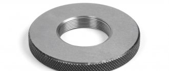
external metric threads use rigid limit ring gauges (GOST 17763-72 and GOST 17764-72), as well as threaded clamps. Internal threads are controlled using thread plug gauges (GOST 17756-72 and GOST 17759-72). When using threaded plug gauges and rings, the pass gauge acts as a complex meter. A no-go gauge is used to measure the limiting size of the average diameter.
Ring gauge M 1.1x0.25 6h PR for complex control and measurement of external metric threads
During element-by-element inspection
the outer diameter of the bolt is checked with any instruments that are usually used to control the diameter of shafts. And the inner diameter of the nut is used for hole control.
To control the average diameter, contact and non-contact methods are used. The first is based on the use of micrometer inserts or three wires.
Measuring mean diameter with thread micrometer inserts
A thread micrometer with inserts is used to measure the average diameter of a triangular thread with profile angles of 60 and 55 degrees. The measurement is carried out in the range from 0 to 350 mm. For each 25 mm interval, either a separate micrometer or special interchangeable anvils are used.
Threaded micrometer MVM-50 GRIFF with inserts for measuring average diameter
The standard kit includes two inserts: a prismatic one, which is placed instead of the micrometer heel, and a conical one, installed in the hole of the micrometer screw.
The micrometer can be equipped with one of five sets of inserts, which are selected depending on the pitch of the thread being tested: 0.4–0.5; 0.6–0.8; 1–1.5; 1.75–2.5; 3–4.5 mm.
Monitoring the thread pitch and profile angle using indicator measuring instruments
The thread pitch and profile angle are measured using microscopes and projectors. In this case, the average diameter of the internal thread is controlled:
- indicator devices with sliding half-plugs;
- indicator devices with sliding inserts;
- horizontal optimeters using measuring arcs with ball measuring tips.
It is convenient to measure the dimensions of parts during processing using an indicator device. Thanks to the special design of the stop bar, this device allows you to install the indicator holder in a convenient place. The device is universal and can be used both for boring and turning.
Indicator device for active dimensional monitoring during lathe processing
The use of indicators and setting rings with the nominal size of the hole being machined reduces the time for preliminary operations and ensures high accuracy in measuring the internal dimensions of the thread.
When processing holes, the cutter is adjusted according to the indicator to remove the first chip with an allowance of 0.1–0.2 mm per side. After this, the indicator readings are measured, and the first chips are removed. The resulting hole size is measured with an indicator device adjusted to the setting ring with the nominal hole size. When setting up, the indicator device is set to zero.
After measuring the hole, they determine which layer of metal needs to be removed to obtain the final size of the hole. Then, according to the indicator, the cutter is installed under the boring of the finishing hole. This measurement method simplifies boring holes according to accuracy classes 2 and 3.
If the batch of parts is large, it is more convenient to first perform preliminary boring of all products with an allowance of 0.3–0.5 mm per diameter, and then complete the finishing boring in one pass with a rigid cutter. The use of indicator devices allows you to work confidently and with great accuracy. However, the indicator does not eliminate the need to use maximum calibers. Measuring the thread with a gauge is a mandatory procedure that is required for final size control.
Defect detection methods
The technical condition of parts is determined by external inspection, tapping, dimensional measurement, checking using universal tools, special templates, devices, fixtures and stands.
During inspection, external damage to parts, deformations, cracks, scuffs, breaks, burnouts, cavities, corrosion, leaks, etc. are revealed.
By tapping, the condition of fixed joints is determined (loose fits of rivets, pins, pins, rings), and the presence of cracks in body parts. When lightly tapped, tightly seated and stationary parts produce a ringing metallic sound, and if there are cracks or a weak fit, they produce a rattling, dull sound.
Using universal measuring instruments, the actual dimensions, deviations from the dimensions, shape, and relative positions of the structural elements of the part are determined. The gap in the connections is measured. To determine the geometric parameters of parts, calipers, micrometers, indicator bore gauges, caliper gauges, etc. are used. The measurement procedure, the tool used, devices, and the location of measurements are indicated in the corresponding technological maps.
In order to increase productivity and simplify the control and sorting of parts, defect detection gauges (hard limit tools) and templates are used in specialized repair production. Templates are made according to the principle of single-limit staples.
Curvature, twisting, beating and warping of the surfaces of parts are determined using special devices and devices. For this purpose, surface plates are used; universal tripods with dial indicators, special prisms and centers, rulers, squares, probes.
Hidden defects in parts (cracks, cavities, etc.) are detected using pneumatic, hydraulic, magnetic, capillary and ultrasonic methods.
The pneumatic method is used to check the tightness of radiators, fuel tanks, fuel lines, rubber bladders, etc. The part is immersed in a bath of water. If it has more than one hole, then the others are closed with plugs, and air is supplied to the remaining ones. The location of the defect is determined by the bubbles of escaping air.
Using the hydraulic method, special stands are used to check the tightness of block jackets, cylinder heads, engine suction pipes, etc. The part is installed on a stand, the holes are closed with special plugs with gaskets, the internal cavity is filled with water and a certain pressure is created. Water leakage will indicate the location of the crack. The hydraulic method is also used when checking plunger pairs, discharge valves of high-pressure fuel pumps, injectors and fuel lines after repair.
Magnetic flaw detection is used to detect hidden cracks, pores, and slag inclusions in parts made of ferromagnetic materials. The method is based on the appearance of a magnetic scattering field in the area where the defect is located when magnetic force lines pass through the part. Magnetization is accomplished by passing an electric current through the part. Before magnetization, the part is sprinkled with ferromagnetic powder or poured with a suspension consisting of transformer oil (40%), kerosene (60%) with the addition of 50 g/l of magnetic powder. Powder particles are concentrated at the edges of the defect, like the poles of a magnet, and indicate its location and configuration.
Capillary methods make it possible to detect discontinuities (cracks, pores, etc.) in parts made of ferromagnetic and non-magnetic materials. They are based on the ability of some liquids to penetrate the smallest surface discontinuities. These methods include fluorescent and color flaw detection.
The simplest of capillary methods is color flaw detection. The penetrating liquid (kerosene - 65%, transformer oil - 30%, turpentine - 5%) is painted red (sudan is added, 10 g/l). It is applied to a degreased surface and after 5-10 minutes the part is wiped. To reveal a crack, an oil solution is used, which is applied to the surface being tested. As it dries, a pattern appears on the white surface showing the location of the defect.
Active control devices
One of the most progressive methods for measuring thread parameters is considered active. It is especially in demand in conditions of mass and large-scale production. Active control devices allow you to automatically monitor the progress of the technological process and provide the necessary processing accuracy.
Active control devices are usually included in the final processing cycle and, based on the results of the check, issue a command to adjust the cutting tool. There is a second way - to check the dimensions of the product during processing in order to immediately control the amount of movement, cutting conditions and other parameters. Active control devices of this type are used on machines with numerical control.
For automatic control and adjustment, contact and non-contact devices are used. In the first case, the tip of the device comes into contact with the product being measured and may cause errors. To exclude this possibility, the tips of active control devices are made of hard alloys and diamonds.
Principles of construction of control devices
With automated control of parameters, the objectivity and repeatability of control results are of particular importance. It is obvious that the “human factor” significantly reduces the reliability of the results, therefore, with varying degrees of automation of the measurement process, the collection and processing of information must remain with the machine
In addition, it is important to leave the possibility of integrating a control device into automated production by ensuring that the product is supplied to the control position by workshop automated transport
It is fundamentally important from the point of view of the possible use of devices for monitoring the geometric parameters of threads of couplings and pipes in the same production (uniform operational characteristics, selection of pipe-coupling pairs, unity of rejection criteria) that they are built on the same kinematic diagram, allowing the use of common methods of collection, processing and analysis information about thread parameters. When designing thread inspection devices, the following points can be identified that affect the quality of information and the reliability of the result:
When designing thread inspection devices, the following points can be identified that affect the quality of information and the reliability of the result:
- the size of the controlled zone (surface) of the thread;
- technology for collecting and processing information;
- accuracy of measuring heads positioning in relation to the thread surface in the process of automated feeding and fixing of the object at the measuring position;
- the amount of information received that allows us to formulate adequate rejection criteria.
The UKRT1 and UKRM1 devices developed at TELECON for monitoring the threads of tubing and couplings, respectively, use the method of visual non-contact monitoring of parameters using industrial video cameras operating in transmission for tubing and in reflection for couplings.
To improve inspection performance, two video cameras are used, located in the center plane of the object, providing simultaneous inspection of two thread zones spaced 180º apart. Control of the maximum size of the thread surface is ensured by two scanning mechanisms: rotation of measuring video cameras around the axis of the part in increments of 22.5º (taking into account 2 video cameras of such control zones, 16) and movement of measuring video cameras along the axis of the part along the entire length of the thread. As a result, inspection is carried out on ~75% of the thread surface of the pipe or coupling, which provides sufficient information to make a decision about its suitability.
Of great importance for minimizing systematic measurement errors on automated control devices is the accuracy and repeatability of the relative position of the measuring video cameras and the object. This is especially true in the case of automated supply of parts to the measuring position by workshop vehicles. If the device is intended for measuring several standard sizes of parts, then it is advisable to minimize the readjustment process so as not to lose the reference bases and spatial position of the axes. This can be done either by increasing the field of view (while maintaining resolution) or by using interchangeable measuring heads, pre-adjusted at the factory.
The total position error of the part consists of the error in the shape of the part, the misalignment of the part and the measuring heads, as well as the non-parallelism of the axis of movement of the heads and the base plate. Obviously, to implement the requirements of GOST 633-80, the total error should not exceed 5-10 microns. In this case, the adjustment of the device (including when readjusting to another standard size) should ensure its own error of no higher than 2-5 microns. All this increases the requirements both for the kinematic structure of the device and for the accuracy of manufacturing and assembly of the used units: guides, supports, base plates, etc.
Measuring threads using the three-wire method
The three-wire method is often used to measure the average diameter of a thread. The diameter is determined by placing wires of the same size on the recesses of the threaded connections. The parameters of the resulting structure are measured with a micrometer. The final calculation results are greatly influenced by the profile error. To eliminate it, the wires are placed on the profile so that they are connected at the level where the width of the depressions is equal to the width of the protrusions.
Using the Three Wire Method to Measure Threads
In this case, the wires should be arranged as follows:
- The 1st lies on the depression on the left side;
- 2nd and 3rd on the depressions of the opposite side.
It is necessary to ensure that during measurement the part does not deform and the wires do not bend.
The size of all three wires used to measure the average thread diameter using this method is selected according to a special table, taking into account the pitch and angle of the thread profile. The ideal diameter is d = tan α /2c, where cs is the pitch, and α /2 is the profile angle of the thread being tested.
In addition to the average diameter, the diameter of the trapezoidal thread is measured using the three-wire method.
Trapezoidal
Threaded connections of this type most often include screw-nut type connections. Trapezoidal threads are made in accordance with GOST 9481-81. Its shape is an isosceles trapezoid. The angle of inclination of the edges is 30°. For the threads of fasteners used in worm gears, an inclination angle of 40° is provided.
The trapezoidal thread profile allows for increased connection strength. Due to this, it is used to connect parts of mechanisms that operate under the influence of dynamic loads, for example, in running nuts that secure valve stems, etc.
Thread pitch measurement
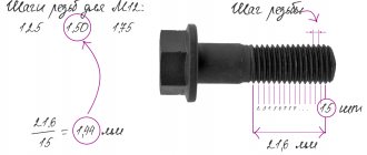
To measure the thread pitch, use a caliper or ruler. To do this, determine the length of several steps and divide it by the number of steps. The pitch of internal and external threads is determined by a thread gauge. Each plate indicates the step size. In this case, the plates are selected so that the teeth fit tightly into the thread. Thanks to this, the pitch coincides with the pitch on the plate.
To measure the thread pitch, standard rulers with millimeter and inch graduations and thread gauges are used. The results of calculating the pitch with a ruler are inaccurate, so the main task when taking measurements is to find the number of turns that fall on a single thread pitch. Let's say if there are 5 turns per 1 inch, the pitch will be 1/5 inch. For convenience, results in inches are converted to millimeters.
To measure the thread pitch correctly, you need to be aware of the following tricks:
- you should measure not individual sections, but the entire part of the part profile;
- before measurement it is necessary to count the whole number of turns;
- The thread pitch is determined after measuring the depth and basic parameters of the threaded connection.
The result of the measurements will be the average step value. The error in the calculations depends on how correctly the thread is cut on the part.
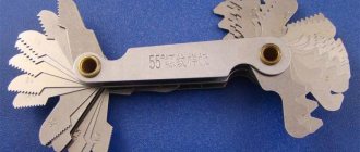
The thread gauge provides the most accurate pitch measurements for pipe and tapered threads because it works with the tightest distances. The design includes plates made of iron alloys. Each plate has cutouts equal to the cutting profile and its pitch.
To determine the pitch size, a thread gauge is applied to the part. In this case, it is necessary to ensure that the plate is parallel to the cutting axis and matches the size of the thread hole.
Thread calibration after galvanizing!
#1 Glavtech
- Name: Viktor
- Field of activity: Manufacturing
Registered 2 messages
Tell me how to calibrate threads after galvanizing; it is advisable to avoid manual calibration of parts using dies. Thanks in advance
- Name: Bityukov A.V.
Field of activity: Manufacturing 710 messages registered
Doesn’t the fact that calibration damage the coating bother you?
- Name: Viktor
Field of activity: Manufacturing 2 messages registered
No! Because Now we do the calibration manually, with a die!
#4 Waltham
- Name: Vanya
Field of activity: Technology development 19 messages registered
Doesn’t the fact that calibration damage the coating bother you?
I'm also interested in this moment. galvanizing to a sufficient depth is carried out so that calibration does not overlap it?!
#5 ingenercons
- Name: Vladimir
Field of activity: Construction 4,549 messages registered
More than once I have seen in the technical requirements the entry after coating, calibration of the thread is prohibited. Actually I agree with this phrase. The meaning of coverage is lost.
Field of activity: Technology development 2,771 messages registered
#7 ingenercons
- Name: Vladimir
Field of activity: Construction 4,549 messages registered
A question arose close to the topic, let’s say there is a bolt with a zinc coating and a similar nut, they tightened it once to check, a second time to check by the customer, and then the installation stage began and the coating peeled off. Or is this not a real situation))
#8 statist
- Field of activity: Design
395 messages registered
A question arose close to the topic, let’s say there is a bolt with a zinc coating and a similar nut, they tightened it once to check, a second time to check by the customer, and then the installation stage began and the coating peeled off. Or is this not a real situation))
If there is too much phosphorus in the steel, for example, then the zinc may flake off. And in principle, such a situation may arise: the engineering staff carefully tightened it a couple of times - everything is fine. And the locksmith Vasily kissed the key with all his heart, and goodbye galvanization. Then we take some polyurethane zinc paint, a brush and bring everything back to its divine glory.
#9 ingenercons
- Name: Vladimir
Field of activity: Construction 4,549 messages registered
How well will the paint protect? I heard there are special formulations. but haven't used it in practice. Or here’s a situation closer to practice: they threw in too long bolts in a hurry, then it doesn’t work during installation, they sawed off with a grinder and inserted it, but in fact the end is exposed metal.
#10 statist
- Field of activity: Design
395 messages registered
Well, of course, it will not replace hot-dip galvanizing itself. But for careful installation and subsequent “not touching” it is quite suitable.
Field of activity: Technology development 2,771 messages registered
#12 ingenerkons
- Name: Vladimir
Field of activity: Construction 4,549 messages registered
Not varnish is not always suitable, just take the same weather conditions, it is better to immediately paint over it with enamel along with the flanges. But what if the conditions involve exposure to various aggressive environments?
Field of activity: Technology development 2,771 messages registered
#14 Disegnatore
- Field of activity: Design
283 messages registered
“Calibration of threads after galvanic coating is not performed/allowed.” A similar phrase can be found in a bunch of books on the topic (for example, Melnikov P.S. Handbook on electroplating in mechanical engineering) and GOSTs (GOST R 51906-2002).
If you don’t care about galvanizing in the thread zone, then the manufacturer can relieve itself of responsibility by including in the contract phrases like “Threaded connections after galvanizing are subject to calibration by the Customer.” or “In the thread area, the thickness of the coating is not regulated.” And then at least calibrate, at least “run” the thread again, removing the galvanic coating to the “ferrous” metal.
source
Measuring the average diameter of a thread
To measure the average diameter of a thread, you must use a thread micrometer complete with different tips (one with a cone, the other with a cutout). The measurement limit is usually indicated on the measuring instruments themselves. Thus, the marking M 3–5 means that the kit allows you to measure threads in increments of 3; 3.5; 4; 4.5 and 5 mm.
Inserts for thread micrometer
A micrometer is used to measure the average thread diameter. Replaceable tool tips are inserted into the screw hole and allow for the most accurate measurements.
If averaged values are sufficient as a result, calipers can be used instead of a micrometer. By design, it consists of ball tips, the dimensions of which must match the type and pitch of the threaded connection. To find out the average diameter, the tips of the calipers must be aligned with the thread gauge. Then the procedure is repeated with the sides of the part. Threaded clamps are used to evaluate measurement results. And the accuracy of the diameter is checked by comparing the resulting thread with the template.
To control the average diameter of a thread consisting of a maximum of two turns, use the two-wire method. The measurement is carried out as follows: wires, the diameter of which coincides with one of the tabular units, are placed on the opposite protrusions and recesses of the thread. In this case, the distance between the ends of the wires shows the average diameter of the part. For each accuracy class, separate wires are created that comply with GOST 2475-88. When deriving final numbers, possible errors are taken into account, because the two-delay method does not allow achieving accurate values.
Another method for measuring the average thread diameter is to use a microscope. The device is applied to the side of the workpiece profile, and the eyepieces are pointed at the profile image on each side to determine its size. The values obtained as a result of measurements are added and divided by the number of sides. The resulting arithmetic mean is the average diameter of the threaded connection.
Tools for manual thread cutting
When cutting threads manually, the workpiece (rod, pipe) is stationary, and the tool itself rotates. In this case, there is no peripheral sliding speed, so the thread cutting tools practically do not heat up to high temperatures. To reduce mechanical wear of the thread-forming profile and reduce the effort, the area of the workpiece required for cutting is lubricated. If there are large differences between the diameter of the original workpiece and the diameter of the thread, it is also necessary to lubricate the inner surface of the hole.
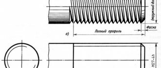
It is believed that in order to form a full-fledged threaded profile, the diameter of the initial workpiece (for the most popular diameters) must correspond to the following values:
| Diameter of cut thread | M6 | M8 | M10 | M12 | M16 | M20 |
| Diameter of the original rod (or tubular blank), mm | 5,80…5,95 | 7,75…7,90 | 9,70…9,95 | 11,80…11,95 | 15,80…15,95 | 19,80…19,95 |
Note : The data given in the table can also be used to determine the diameter of the initial workpiece for subsequent thread shaping on machines with flat dies.
An important element for choosing the right lecher is the material from which it is made. The peculiarity of the thread cutting process - a gradual increase in force, with a sharp decrease towards the end of the process - determines the increased viscosity of the threading material, otherwise the thread profile will intensively chip. Therefore, the optimal choice would be levers made of alloy tool steel X12F1 or 9ХС, with a hardness of 59…61HRC. For cutting threads on heat-resistant and alloy steels, a tool made of high-speed steel grades R6M5 or R9K6, with a hardness of 60...63 HRC, is suitable. The price of such blades will be high, so their use is justified only for large volumes of production of threaded parts. For domestic purposes, it is quite acceptable to use lerks made from carbon tool steels U10 or U12.
Among the enterprises that produce such tooling, the highest ratings are those of Izhevsk, Chelyabinsk, Vladivostok, Samara, Bryansk, Nizhny Novgorod (Russia), Orsha, Minsk (Belarus), and Lvov (Ukraine). Foreign-made lechers from UFC (Italy) and CM Tools (Finland) have proven themselves to be excellent in operation.
Measuring the outer diameter of a thread
To measure external threads, micrometric instruments are used, the basis of which are microscrews. Control is carried out according to this scheme.
- Microscrews are applied to the thread profile. The position of the instrument is adjusted by rotating the micrometer several times.
- Record the size of the cutting profile for one side. The value is calculated based on the division value on the microscrew scale.
- The micrometer is applied to the opposite end of the profile and its size is calculated.
- The result of measuring the outer diameter of the thread is determined by subtracting the result of the second from the result of the first calculation.
How is the operation performed and what is its essence?
The main task of the mechanic is to create a hole in the metal thickness with the subsequent formation of hollows from the inside. They need to be made so that the turns fit the bolt, stud or other fastener.
A threaded element may be needed in everyday life for the most durable connection of two parts. Here it is necessary to achieve maximum cleanliness - so that there are no shavings, deformations, or broken threads left. It is also very important to follow GOST standards for the size of the device. The diameter should match the screw that will go inside.
Many parameters are important - the type of material, its density, as well as condition, for example, temperature, the presence of corrosion. First you need to prepare the workpiece - remove excess dirt. Then you need to select the right tool, and only then begin metalworking in two or three stages - from roughing to finishing.
Several parameters matter:
- hole diameter;
- cutting depth;
- number of threads (these are entries, the most common is the presence of three cavities);
- pitch, that is, the distance between two furrows.
Measuring the internal diameter of a thread
The internal thread is measured using calipers. The tool is installed on a template part using a thread gauge, and then compared with the original internal diameter of the threaded connection. To obtain accurate values, the caliper must be positioned at an angle to the axis being measured.
You can also use cylindrical thread gauges to measure the internal diameter of a thread. This is because the inner diameter has a smooth surface and is ideal for the shape of the tips used in these instruments. The results obtained are checked using plug gauges.
Application of calibers
Insert plugs are the main type of threaded plugs and have a tapered shank. They are manufactured with diameters from 1 to 50 mm. The sealing of threaded connections with an outer diameter from 50 to 100 mm is made in the form of nozzles, fixed at the ends of the plastic handle with screws. External threads are checked using threaded rings made with a diameter of 1 to 100 mm. Pass-through rings are cut along the entire width of the ring. Their outer surface is rolled. Impassable rings have a shortened thread (only two or three turns with a shortened thread are left). They create a distinctive groove in the middle of the outer knurled cylindrical surface of the ring.
Thread profile measurement
To measure the thread profile, a tool such as a microscope is used, and control is carried out using profiles. The procedure is carried out in the following sequence.
- A normal threaded ring measures the outer diameter.
- A ring is put on the screw, which demonstrates the accuracy of the thread by shaking.
- The diameter is coordinated using a standard threaded plug. At the same time, its protruding smooth end simultaneously serves as a tool for controlling the diameter of the threaded hole.
Tools for machine thread forming
Unlike hand tools, when producing threads on specialized machines, dies perform a reciprocating movement, while the workpiece moves in a screw manner. Such lechers are divided into movable, which is fixed in the slide of the machine, and stationary, installed on its table.
The working area of the fixed ladders consists of three main parts:
- The intake, with the help of which the rod workpiece is captured;
- Profiling, where the thread rolling itself is carried out;
- Calibrating, in the area of which the basic parameters of the thread are calibrated and the product smoothly exits the thread formation zone.
This design eliminates sharp fluctuations in force, which are inevitable due to the operating characteristics of the equipment: high productivity (up to 400 rpm) and the presence of an idle stage, when the slide with the die holder returns to its original position after the next workpiece.
The movable die has a simpler design. Its receiving part in length is approximately 30...35% of the diameter of the original workpiece, while the rise of the profile to the main level of profiling occurs at an angle of 4...7 °, At the same time, the length of the movable lever is always greater: this eliminates accidental capture of the knurled workpiece during the reverse stroke of the slide .
Machine tools can be used to cut not only ordinary types of threads, but also special profiles, for example, for grease nipple heads, as well as threads for self-tapping screws. For this purpose, a special comb is made on the form-forming part of the lerk, in the grooves of which the necessary sharpening of the end of the fastener is formed.
In order to avoid cracks during long-term use of tools for machine thread shaping, their hardness should be slightly lower than manual ones - within 56...58 HRC.
Machine lerks are usually manufactured by the same companies that produce the thread rolling equipment itself. Tools listed are Italian (from the Sima and Sacma brands), Japanese (Sakamura) and Belgian-made (Malmedie). It is better to avoid commercially available tools made in China and Taiwan: although its price is much lower, the stability of its performance characteristics and mechanical properties are highly questionable.
Where to buy thread measuring tools?
You can buy the necessary tools for measuring threads in the Rincom online store. Always in stock:
- calipers;
- probes;
- micrometers;
- calibers.
You can place an order with delivery throughout Russia directly on the website. It is possible to manufacture measuring instruments according to your drawings. The batch size of products is not limited. I