RS is a standard that describes an interface for serial bidirectional data transfer between a terminal (DTE, Data Terminal Equipment) and a terminal device (DCE, Data Circuit-Terminating Equipment), that is, a serial connection of devices where the data transfer process occurs one bit at a time ( serially) over a communication channel or computer bus. A serial connection is used for long-distance communications and computer networks, where, given the cost of cable and synchronization difficulties, the use of a parallel connection is ineffective. Below is a brief description and pinout of such connectors.
RS-232C DE-9 connectors
| Contact number | Purpose | Designation |
| 1 | Active carrier | DCD |
| 2 | Computer reception | RXD |
| 3 | Computer transmission | TXD |
| 4 | Readiness for exchange on the part of the receiver | DTR |
| 5 | Earth | GND |
| 6 | Willingness to exchange on the part of the source | DSR |
| 7 | Transfer request | RTS |
| 8 | Ready for transfer | CTS |
| 9 | Call tone | R.I. |
The RS232C DE-9 (commonly incorrectly called DB-9) port is available on some PCs and many other devices. The RS-232 serial port was once a standard feature of PCs, used to connect to modems, printers, mice, data storage, uninterruptible power supplies, and other peripherals.
| DE-9 Pin | Signal | Direction | Description |
| 1 | DCD | < | Data Carrier Detect |
| 2 | RXD | < | Receive Data |
| 3 | TXD | > | Transmit Data |
| 4 | DTR | > | Data Terminal Ready |
| 5 | 0V/COM | – | 0V or System Ground |
| 6 | DSR | < | Data Set Ready |
| 7 | RTS | > | Request to Send |
| 8 | CTS | < | Clear to Send |
| 9 | R.I. | < | Ring Indicator |
RS-232 is a standard that appeared back in 1960 for serial data transmission. It formally defines the signals connecting DTE (Data Terminal Equipment), such as a computer terminal, and DCE (Data Communications Equipment), such as a modem. The RS-232 standard was commonly used in computer serial ports.
RS-232, compared to later interfaces such as RS-422, RS-485 or Ethernet, has lower transmission speeds, shorter maximum cable lengths, greater voltage fluctuations, larger standard connectors, and no multipoint capability. In modern personal computers, USB has long replaced RS-232 from most peripheral interface functions. Many computers do not have RS-232 ports at all and must use either an external USB-to-RS232 converter or an internal expansion card with one or more serial ports to connect to RS-232 peripherals.
However, due to its simplicity and ubiquity, RS-232 interfaces are still used - for example in industrial machines, networking equipment and scientific instruments where a short-range, point-to-point, low-speed wired connection is sufficient to transmit data.
This PC serial port interface is single-ended (connects only two devices via RS232 serial cable), the data transfer rate is less than 20 kbps. Hot swapping is not supported, but is sometimes allowed. Currently, only the 9-pin connector is used for PCs.
Configuration and interrupts
Since a computer can have several serial ports (up to 4), the system allocates two hardware interrupts for them - IRQ 3 (COM 2 and 4) and IRQ 4 (COM 1 and 3) and several BIOS interrupts. Many communication programs, as well as built-in modems, use interrupts and the address space of COM ports for their work. In this case, not real ports are usually used, but so-called virtual ports, which are emulated by the operating system itself.
As with many other motherboard components, the COM port parameters, in particular the BIOS interrupt values corresponding to hardware interrupts, can be configured through the BIOS Setup interface. For this, BIOS options such as COM Port, Serial Port, Onboard Serial Port, Serial Port Address, etc. are used.
RS-232 25 pin connectors
RS-232 data transmission consists of a time series of bits. Both synchronous and asynchronous transmission are supported, but an asynchronous channel, sending packets of seven or eight bits, is the most common configuration on PCs. RS-232 devices can be classified as data terminal equipment (DTE) or data communications equipment (DCE) - this determines which wires will send and receive each signal. Personal computers are usually equipped with a simplified version of the RS-232 interface.
| № | Designation | Direction | Signal name |
| 1 | n/c | – | |
| 2 | TXD | Exit | Transmit Data |
| 3 | RXD | Entrance | Receive Data |
| 4 | RTS | Exit | Request to Send |
| 5 | CTS | Entrance | Clear to Send |
| 6 | DSR | Entrance | Data Set Ready |
| 7 | GND | – | System Ground |
| 8 | DCD | Entrance | Data Carrier Detect |
| 9 | n/c | – | BUTTON_POR (Power-on reset) for Sun Ultra 80 / Sun Blade 1000 / Sun Blade 2000 / Sun Fire 280R / Enterprise 420R |
| 10 | n/c | – | BUTTON_XIR_L (Transmit internal reset) for Sun Ultra 80 / Sun Blade 1000 / Sun Blade 2000 / Sun Fire 280R / Enterprise 420R |
| 11 | n/c | – | +5 Vdc for Sun Ultra 80 / Sun Blade 1000 / Sun Blade 2000 / Sun Fire 280R / Enterprise 420R |
| 12 | n/c | – | |
| 13 | n/c | – | |
| 14 | n/c | – | |
| 15 | TRxC | Entrance | Transmit Clock |
| 16 | n/c | – | |
| 17 | RTxC | Entrance | Receive Clock |
| 18 | n/c | – | |
| 19 | n/c | – | |
| 20 | DTR | Exit | Data Terminal Ready |
| 21 | n/c | – | |
| 22 | n/c | – | |
| 23 | n/c | – | |
| 24 | TxC | Exit | Transmit Clock |
| 25 | n/c | – |
RS232 pin signals are represented by voltage levels relative to the common circuit (power/logical ground). In the standby state (MARK), the signal level is negative relative to the common wire, and in the active state (SPACE), the signal level is positive relative to the common wire. RS232 has multiple handshake lines (mostly used with modems) and also defines the communication protocol.
The RS-232 interface assumes a common ground between the DTE and DCE. This is a reasonable assumption when a short cable connects the DTE to the DCE, but with longer lines and connections between devices that may be on different electrical buses with different grounding, this may not be true. RS232 data is bipolar.
The standard specifies a maximum open circuit voltage of 25 V, but common signal levels are 5 V, 10 V, 12 V, and 15 V. Circuits driving an RS-232 compatible interface must withstand an indefinite short circuit to ground or to any voltage level up to 25 volts. +3 to +12 volts indicates the ON or 0 state, while -3 to -12 V indicates the OFF 1 state.
Some computer equipment ignores the negative level and accepts the zero voltage level as the OFF state. In fact, the ON state can be achieved with a lower positive potential. This means that 5VDC powered circuits can directly drive RS232 circuits, but the overall range over which the RS232 signal can be transmitted/received can be significantly reduced.
The output level typically ranges from +12V to -12V. The deadband between +3V and -3V is designed to absorb line noise. In different pinout definitions like RS-232, this dead zone may differ. For example, the definition for V.10 has a deadband of +0.3 V to -0.3 V. Many receivers designed for RS-232 are sensitive to voltage swings of 1 V or less.
Motherboard expansion slots
(not really about cables, but useful)
8 bit slot
| Installation side | Solder side | ||||
| № | Signal | Meaning | № | Signal | Meaning |
| A1 | I/O CH CK | I/O channel monitoring | B1 | GND | Earth |
| A2 | D7 | Data line 8 | B2 | RES DRV | Reset signal |
| A3 | D6 | Data line 7 | B3 | +5V | +5V |
| A4 | D5 | Data line 6 | B4 | IRQ2 | Interrupt request 2 |
| A5 | D4 | Data line 5 | B5 | -5V | -5V |
| A6 | D3 | Data line 4 | B6 | DRQ2 | DMA request 2 |
| A7 | D2 | Data line 3 | B7 | -12V | -12V |
| A8 | D1 | Data line 2 | B8 | RES | Reserved |
| A9 | D0 | Data line 1 | B9 | +12V | +12V |
| A10 | I/O CN RDY | I/O channel readiness monitoring | B10 | GND | Earth |
| A11 | AEN | Address Enable, bus control with CPU and DMA controller | B11 | MEMW | Data is written to memory |
| A12 | A19 | Address line 20 | B12 | MEMR | Data is read from memory |
| A13 | A18 | Address line 19 | B13 | IOW | Data is written to the I/O port |
| A14 | A17 | Address line 18 | B14 | IOR | Data is read from the I/O port |
| A15 | A16 | Address line 17 | B15 | DACK3 | DMA-Acknowledge 3 |
| A16 | A15 | Address line 16 | B16 | DRQ3 | DMA 3 request |
| A17 | A14 | Address line 15 | B17 | DACK1 | DMA-Acknowledge 1 |
| A18 | A13 | Address line 14 | B18 | IRQ1 | Interrupt request 1 |
| A19 | A12 | Address line 13 | B19 | REFRESH | Memory regeneration |
| A20 | A11 | Address line 12 | B20 | CLC | System clock 4.77 MHz |
| A21 | A10 | Address line 11 | B21 | IRQ7 | Interrupt request 7 |
| A22 | A9 | Address line 10 | B22 | IRQ6 | Interrupt request 6 |
| A23 | A8 | Address line 9 | B23 | IRQ5 | Interrupt Request 5 |
| A24 | A7 | Address line 8 | B24 | IRQ4 | Interrupt request 4 |
| A25 | A6 | Address line 7 | B25 | IRQ3 | Interrupt request 3 |
| A26 | A5 | Address Line 6 | B26 | DACK2 | DMA-Acknowledge 2 |
| A27 | A4 | Address line 5 | B27 | T/C | Terminal Count, signals the end of DMA transformation |
| A28 | A3 | Address line 4 | B28 | ALE | Adress Latch Enabled, address/data uncoupling |
| A29 | A2 | Address line 3 | B29 | +5V | +5V |
| A30 | A1 | Address line 2 | B30 | O.S.C. | Clock frequency 14.31818 MHz |
| A31 | A0 | Address line 1 | B31 | GND | Earth |
16 bit slot
| Installation side | Solder side | ||||
| № | Signal | Meaning | № | Signal | Meaning |
| A1 | I/O CH CK | I/O channel monitoring | B1 | GND | Earth |
| A2 | D7 | Data line 8 | B2 | RES DRV | Reset signal |
| A3 | D6 | Data line 7 | B3 | +5V | +5V |
| A4 | D5 | Data line 6 | B4 | IRQ9 | Cascading the second interrupt controller |
| A5 | D4 | Data line 5 | B5 | -5V | -5V |
| A6 | D3 | Data line 4 | B6 | DRQ2 | DMA request 2 |
| A7 | D2 | Data line 3 | B7 | -12V | -12V |
| A8 | D1 | Data line 2 | B8 | RES | Memory communication without latency |
| A9 | D0 | Data line 1 | B9 | +12V | +12V |
| A10 | I/O CN RDY | I/O channel readiness monitoring | B10 | GND | Earth |
| A11 | AEN | Address Enable, bus control with CPU and DMA controller | B11 | SMEMW | Data is written to memory (up to 1M byte) |
| A12 | A19 | Address line 20 | B12 | SMEMR | Data is read from memory (up to 1 MB) |
| A13 | A18 | Address line 19 | B13 | IOW | Data is written to the I/O port |
| A14 | A17 | Address line 18 | B14 | IOR | Data is read from the I/O port |
| A15 | A16 | Address line 17 | B15 | DACK3 | DMA-Acknowledge 3 |
| A16 | A15 | Address line 16 | B16 | DR Q3 | DMA 3 request |
| A17 | A14 | Address line 15 | B17 | DACK1 | DMA-Acknowledge 1 |
| A18 | A13 | Address line 14 | B18 | IRQ1 | Request IRQ 1 |
| A19 | A12 | Address line 13 | B19 | REFRESH | Memory regeneration |
| A20 | A11 | Address line 12 | B20 | CLC | System clock 4.77 MHz |
| A21 | A10 | Address line 11 | B21 | IRQ7 | IRQ 7 request |
| A22 | A9 | Address line 10 | B22 | IRQ6 | IRQ 6 request |
| A23 | A8 | Address line 9 | B23 | IRQ5 | Request IRQ 5 |
| A24 | A7 | Address line 8 | B24 | IRQ4 | IRQ 4 request |
| A25 | A6 | Address line 7 | B25 | IRQ3 | IRQ 3 request |
| A26 | A5 | Address Line 6 | B26 | DACK2 | DMA-Acknowledge 2 |
| A27 | A4 | Address line 5 | B27 | T/C | Terminal Count, signals the end of DMA transformation |
| A28 | A3 | Address line 4 | B28 | ALE | Adress Latch Enabled, address/data uncoupling |
| A29 | A2 | Address line 3 | B29 | +5V | +5V |
| A30 | A1 | Address line 2 | B30 | O.S.C. | Oscillator clock 14.31818 MHz |
| A31 | A0 | Address line 1 | B31 | GND | Earth |
| C1 | SBHE | System Bus High Enabled, 16-bit data signal | D1 | MEMCS 16 | Memory Chip Select |
| C2 | LA23 | Address line 24 | D2 | I/O CS 16 | I/O card with 8 bit/16 bit carryover |
| C3 | LA22 | Address line 23 | D3 | IRQ10 | Interrupt request 10 |
| C4 | LA21 | Address line 22 | D4 | IRQ11 | Interrupt request 11 |
| C5 | LA20 | Address line 21 | D5 | IRQ12 | Interrupt request 12 |
| C6 | LA19 | Address line 20 | D6 | IRQ15 | Interrupt request 15 |
| C7 | LA18 | Address line 19 | D7 | IRQ14 | Interrupt request 14 |
| C8 | LA17 | Address line 18 | D8 | DACK0 | DMA-Acknowledge 0 |
| C9 | MEMR | Reading data from memory | D9 | DRQ0 | DMA request 0 |
| C10 | MEMW | Writing data to memory | D10 | DACK5 | DMA-Acknowledge 5 |
| C11 | SD8 | Data line 9 | D11 | DRQ5 | DMA 5 request |
| C12 | SD9 | Data line 10 | D12 | DACK6 | DMA-Acknowledge 6 |
| C13 | SD10 | Data line 11 | D13 | DRQ6 | DMA 6 request |
| C14 | SD11 | Data line 12 | D14 | DACK7 | DMA-Acknowledge 7 |
| C15 | SD12 | Data line 13 | D15 | DRQ7 | DMA 7 request |
| C16 | SD13 | Data line 14 | D16 | +5V | +5V |
| C17 | SD14 | Data line 15 | D17 | MASTER | Busmaster signal |
| C18 | SD15 | Data line 16 | D18 | GND | Earth |
RS-366 connectors
| Pin | Function | Description | EIA scheme |
| 1 | unused | ||
| 2 | Digit Present | A signal given to the ACE indicating that the digit lines contain a digit | DPR |
| 3 | Abandon Call and Retry | An indicator signal from the ACE that it could not make a connection. Could be “busy”. | ACR |
| 4 | Call Request | A signal from the DTE that tells the ACE to go “off hook” | CRQ |
| 5 | Present Next Digit | A signal from the ACE to the DTE to indicate that the ACE is ready to receive the next digit. | PND |
| 6 | unused | ||
| 7 | unused | ||
| 8 | unused | ||
| 9 | unused | ||
| 10 | unused | ||
| 11 | unused | ||
| 12 | unused | ||
| 13 | Distant Station Connected | Indicator from ACE to DTE that the call is succesfully made. | DSC |
| 14-17 | Digital Signal Circuits | Four lines containing a parallel BCD dial digit (10 digits, plus control digits) | NB1-NB8 |
| 18 | unused | ||
| 19 | unused | ||
| 20 | unused | ||
| 21 | unused | ||
| 22 | Data Line Occupied | An indicator that is used by the ACE to let the DTE know that the line it wants to use is used by another device. | DLO |
| 23 | unused | ||
| 24 | unused | ||
| 25 | unused |
Sample RS232 serial port device. How serial mouse works
Typical PC mouse controlling system has the following parts: sensors -> mouse controller -> communication link -> data interface -> driver -> software. Sensors are the movement detectors which sense the mouse movement and button switches which sense the button states. Mouse controller reads the state of those sensors and takes account of current mouse position. When this information changes the mouse controller sends a packet of data to the computer serial data interface controller. The mouse driver in the computer received that data packet and decodes the information from it and does actions based on the information.
RS-422 9-pin connectors
| Pin | Signal | Description |
| 1 | Shield | |
| 2 | RTS+ | Request To Send + |
| 3 | RTS- | Request To Send – |
| 4 | TXD+ | Transmit Data + |
| 5 | TXD- | Transmit Data |
| 6 | CTS+ | Clear To Send + |
| 7 | CTS- | Clear To Send – |
| 8 | RXD+ | Received Data + |
| 9 | RXD- | Received Data |
^ Theory (can be skipped)
A special program sends data to the computer I/O port (378h). Using certain electronic elements, this port is connected to an external, in this case, LPT port, which outputs this data “outside” in the form of electrical signals.
The classic 8 LEDs are controlled via port 888 (378h), and the four additional LEDs are controlled via port 890 (37Ah). (Base port 378h)
In this case, control over port 890 occurs a little differently, because three of the four channels are inverting.
The whole picture looks like this:
Correspondence between the bits of the I/O ports and the LPT port pins (* - pins with inversion)
| Hardware | Software part | ||
| LED No. | Contact no. | Port No. | Bit no. |
| 1 | 2 | 888 (378h) | |
| 2 | 3 | 888 (378h) | 1 |
| 3 | 4 | 888 (378h) | 2 |
| 4 | 5 | 888 (378h) | 3 |
| 5 | 6 | 888 (378h) | 4 |
| 6 | 7 | 888 (378h) | 5 |
| 7 | 8 | 888 (378h) | 6 |
| 8 | 9 | 888 (378h) | 7 |
| 9 | 1 * | 890 (37Ah) | |
| 10 | 14 * | 890 (37Ah) | 1 |
| 11 | 16 | 890 (37Ah) | 2 |
| 12 | 17 * | 890 (37Ah) | 3 |
You can see the LED connected directly to the contacts (pins) of the LPT port in the article “LED testing of the LPT port”.
RS-422 37-pin connectors
RS422 is a balanced serial interface for transmitting digital data. The advantage of a balanced signal is greater noise immunity. The EIA describes RS422 as a DTE-DCE interface for point-to-point connections.
| Pin | Name | Eg. | Description |
| 1 | GND | – | Shield Ground |
| 2 | SRI | < | Signal Rate Indicator |
| 3 | n/c | – | Spare |
| 4 | SD | > | Send Data |
| 5 | ST | > | Send Timing |
| 6 | R.D. | < | Receive Data |
| 7 | RTS | > | Request To Send |
| 8 | R.R. | < | Receiver Ready |
| 9 | CTS | < | Clear To Send |
| 10 | LL | > | Local Loopback |
| 11 | DM | < | Data Mode |
| 12 | TR | > | Terminal Ready |
| 13 | R.R. | < | Receiver Ready |
| 14 | R.L. | > | Remote Loopback |
| 15 | IC | < | Incoming Call |
| 16 | SF/SR | > | Select Frequency/Select Rate |
| 17 | TT | > | Terminal Timing |
| 18 | TM | < | Test Mode |
| 19 | GND | – | Ground |
| 20 | R.C. | – | Receive Twister-Pair Common |
| 21 | GND | – | Spare Twister-Pair Return |
| 22 | /SD | – | Send Data TPR |
| 23 | GND | – | Send Timing TPR |
| 24 | /RD | – | Receive Data TPR |
| 25 | /RS | – | Request To Send TPR |
| 26 | /RT | – | Receive Timing TPR |
| 27 | /CS | – | Clear To Send TPR |
| 28 | IS | < | Terminal In Service |
| 29 | /DM | – | Data Mode TPR |
| 30 | /TR | – | Terminal Ready TPR |
| 31 | /RR | – | Receiver TPR |
| 32 | SS | > | Select Standby |
| 33 | S.Q. | < | Signal Quality |
| 34 | N.S. | > | New Signal |
| 35 | /TT | – | Terminal Timing TPR |
| 36 | S.B. | < | Standby Indicator |
| 37 | S.C. | – | Send Twister Pair Common |
RS422 was designed for longer distances and higher transmission speeds than RS232. In its simplest form, a pair of RS232 to RS422 (and vice versa) converters can be used to form an "RS232 extender". Data transfer rates up to 100K bps and distances up to a kilometer. RS422 is also intended for multi-drop (group) devices, where only one driver is connected and transmits up to 10 receivers over the bus.
Both RS-422 and RS-485 use twisted pair (that is, 2 wires) for each signal. Both use the same differential drive with the same voltage swing: 0 to +5 V, but RS-422 is a multidrop standard allowing one driver and up to 10 receivers, and RS-485 allows up to 32 devices (drivers, receivers or transceivers).
Because the basic RS-423-A and RS422-A receivers are electrically identical, it is possible to connect equipment using RS423-A receivers and generators on one side of the interface to equipment using RS422-A generators and receivers on the other side of the interface if the receivers' pins and generators are properly configured to accommodate this layout.
Connector interface
The basic Centronics interface is a unidirectional parallel interface and contains signal lines characteristic of such an interface (8 for data transmission, strobe, device status lines).
Data is transferred in one direction: from the computer to an external device. But it cannot be called completely unidirectional. Thus, 4 return lines are used to monitor the status of the device. Centronics allows you to connect one device, so to use multiple devices together, you need to additionally use a selector.
Data transfer speed can vary and reach 1.2 Mbit/s.
Simplified table - Centronics LPT interface signal diagram - connector
| DB-25 IEEE 1284-A pins | Contact Centronics IEEE 1284-B | Designation | Note | Function |
| 1 | 1 | Strobe | Transfer cycle marker (output) | Computer Management |
| 2 | 2 | Data Bit 1 | Signal 1 (output) | Data Computer |
| 3 | 3 | Data Bit 2 | Signal 2 (output) | Data Computer |
| 4 | 4 | Data Bit 3 | Signal 3 (output) | Data Computer |
| 5 | 5 | Data Bit 4 | Signal 4 (output) | Data Computer |
| 6 | 6 | Data Bit 5 | Signal 5 (output) | Data Computer |
| 7 | 7 | Data Bit 6 | Signal 6 (output) | Data Computer |
| 8 | 8 | Data Bit 7 | Signal 7 (output) | Data Computer |
| 9 | 9 | Data Bit 8 | Signal 8 (output) | Data Computer |
| 10 | 10 | Acknowledgment | Willingness to accept (input) | Printer Status |
| 11 | 11 | Busy | Busy (entrance) | Printer Status |
| 12 | 12 | Paper End | No paper (input) | Printer Status |
| 13 | 13 | Select | Select (input) | Printer Status |
| 14 | 14 | Auto Line Feed | Autofeed (output) | Computer Management |
| 15 | 32 | Error | Error (input) | Printer Status |
| 16 | 31 | Init | Initialize (exit) Initialize Printer (prime-low) | Computer Management |
| 17 | 36 | Select In | Print Control (Output) Select Input | Computer Management |
| 18-25 | 16-17, 19-30 | GND | General | Earth |
You can download the wiring for the Centronics IEEE 1284 Printer Cable lpt - com9 port in the form of a picture image here -
. It is often more convenient to use it for printing the diagram.
Based on materials from https://ru.wikipedia.org/wiki/LPT
Complete Tables - Centronics LPT Interface Signal Diagram - IEEE-1284:
IEEE-1284A Pinning Sub-D25 A-connector:
IEEE-1284B Pinning 36 pin Amphenol B-connector:
IEEE-1284C Pinning MDR 36 pins C-connector:
Signals - Decoding - Pin Signal Source of Centronics IEEE 1284 Printer lpt cable:
RS-423 connectors
| Description | RS423 | RS422 | |
| Mode of Operation | SINGLE – ENDED | DIFFERENTIAL | |
| Total Number of Drivers and Receivers on One Line | 1 DRIVER 10 RECVR | 1 DRIVER 10 RECVR | |
| Maximum Cable Length | 4000 ft. | 4000 ft. | |
| Maximum Data Rate | 100kb/s | 10Mb/s | |
| Maximum Driver Output Voltage | +/-6V | -0.25V to +6V | |
| Driver Output Signal Level (Loaded Min.) | Loaded | +/-3.6V | +/-2.0V |
| Driver Output Signal Level (Unloaded Max) | Unloaded | +/-6V | +/-6V |
| Driver Load Impedance (Ohms) | >450 | 100 | |
| Max. Driver Current in High Z State | Power On | N/A | N/A |
| Max. Driver Current in High Z State | Power Off | +/-100uA | +/-100uA |
| Slew Rate (Max.) | Adjustable | N/A | |
| Receiver Input Voltage Range | +/-12V | -10V to +10V | |
| Receiver Input Sensitivity | +/-200mV | +/-200mV | |
| Receiver Input Resistance (Ohms) | 4k min. | 4k min. | |
RS-423 is similar to TIA/EIA-232-F, but features reduced driver output swing and higher data rates. RS-423 is an electrical standard that specifies only driver and receiver requirements—there is no common pinout for this interface. An unbalanced driver and a balanced receiver are defined. TIA/EIA-423-B defines a unidirectional, multipoint (up to 10 receivers) interface. Advantages over TIA/EIA-232-F include: multi-receiver operation, higher data rates, and shared power supplies (typically 5V).
Useful: Pinout of mounting blocks for VAZ cars
Now let's move on to the USB 3.0 port
The second name for a USB 3.0 port is USB Super Speed, due to the increased data transfer speed of up to 5 Gb/sec. To increase speed indicators, engineers used full-duplex (two-wire) transmission of both sent and received data. Due to this, 4 additional contacts appeared in the connector -/+ StdA_SSRX and -/+StdA_SSTX. In addition, increased speeds required the use of a new type of controller with higher power consumption, which led to the need to use additional power pins in the USB 3.0 connector (DPWR and DGND). The new type of connector began to be called USB Powered B. In a digression, let’s say that the first Chinese flash drives for this connector were made in cases without taking into account the thermal characteristics of their controllers and, as a result, they got very hot and failed.
RS-449 connectors
| Pin | Name | V.24 | Eg. | Description | Type |
| 1 | 101 | – | Shield | Ground | |
| 2 | S.I. | 112 | > | Signal Rate Indicator | Control |
| 3 | n/a | n/a | unused | ||
| 4 | SD- | 103 | > | Send Data (A) | Data |
| 5 | ST- | 114 | < | Send Timing (A) | Timing |
| 6 | RD- | 104 | < | Receive Data (A) | Data |
| 7 | RS- | 105 | > | Request To Send (A) | Control |
| 8 | RT- | 115 | < | Receive Timing (A) | Timing |
| 9 | CS- | 106 | < | Clear To Send (A) | Control |
| 10 | LL | 141 | > | Local Loopback | Control |
| 11 | DM- | 107 | < | Data Mode (A) | Control |
| 12 | TR- | 108.2 | > | Terminal Ready (A) | Control |
| 13 | RR- | 109 | < | Receiver Ready (A) | Control |
| 14 | R.L. | 140 | > | Remote Loopback | Control |
| 15 | IC | 125 | < | Incoming Call | Control |
| 16 | SF/SR+ | 126 | > | Signal Freq./Sig. RateSelect. | Control |
| 17 | TT- | 113 | > | Terminal Timing (A) | Timing |
| 18 | TM- | 142 | < | Test Mode (A) | Control |
| 19 | S.G. | 102 | – | Signal Ground | Ground |
| 20 | R.C. | 102b | – | Receive Common | Ground |
| 21 | n/a | n/a | unused | ||
| 22 | SD+ | 103 | > | Send Data (B) | Data |
| 23 | ST+ | 114 | < | Send Timing (B) | Timing |
| 24 | RD+ | 104 | < | Receive Data (B) | Data |
| 25 | RS+ | 105 | > | Request To Send (B) | Control |
| 26 | RT+ | 115 | < | Receive Timing (B) | Timing |
| 27 | CS+ | 106 | < | Clear To Send (B) | Control |
| 28 | IS | n/a | > | Terminal In Service | Control |
| 29 | DM+ | 107 | < | Data Mode (B) | Control |
| 30 | TR+ | 108.2 | > | Terminal Ready (B) | Control |
| 31 | RR+ | 109 | < | Receiver Ready (B) | Control |
| 32 | SS | 116 | < | Select Standby | Control |
| 33 | S.Q. | 110 | < | Signal Quality | Control |
| 34 | N.S. | n/a | > | New Signal | Control |
| 35 | TT+ | 113 | > | Terminal Timing (B) | Timing |
| 36 | S.B. | 117 | < | Standby Indicator | Control |
| 37 | S.C. | 102a | – | Send Common | Ground |
| Name | Description | Function |
| A.A. | Shield Ground | Also known as protective ground. This is the chassis ground connection between DTE and DCE. |
| AB | Signal Ground | The reference ground between a DTE and a DCE. Has the value 0 Vdc. |
| B.A. | Transmitted Data | Data sent by the DTE. |
| BB | Received Data | Data received by the DTE. |
| C.A. | Request To Send | Originated by the DTE to initiate transmission by the DCE. |
| C.B. | Clear To Send | Send by the DCE as a reply on the RTS after a delay in ms, which gives the DCEs enough time to energize their circuits and synchronize on basic modulation patterns. |
| CC | DCE Ready | Known as DSR. Originated by the DCE indicating that it is basically operating (power on, and in functional mode). |
| CD | DTE Ready | Known as DTR. Originated by the DTE to instruct the DCE to setup a connection. Actually it means that the DTE is up and running and ready to communicate. |
| C.E. | Ring Indicator | A signal from the DCE to the DTE that there is an incoming call (telephone is ringing). Only used on switched circuit connections. |
| CF | Received Line Signal Detector | Known as DCD. A signal send from DCE to its DTE to indicate that it has received a basic carrier signal from a (remote) DCE. |
| CH/CI | Data Signal Rate Select (DTE/DCE Source> | A control signal that can be used to change the transmission speed. |
| D.A. | Transmit Signal Element Timing (DTE Source) | Timing signals used by the DTE for transmission, where the clock is originated by the DTE and the DCE is the slave. |
| D.B. | Transmitter Signal Element Timing (DCE Source) | Timing signals used by the DTE for transmission. |
| DD | Receiver Signal Element Timing (DCE Source) | Timing signals used by the DTE when receiving data. |
| IS | terminal In Service | Signal that indicates that the DTE is available for operation |
| N.S. | New Signal | A control signal from the DTE to the DCE. It instructs the DCE to rapidly get ready to receive a new analog signal. It helps master-station modems rapidly synchronize on a new modem at a tributary station in multipoint circuits |
| R.C. | Receive Common | A signal return for receiver circuit reference |
| LL | Local Loopback/Quality Detector | A control signal from the DTE to the DCE that causes the analog transmision output to be connected to the receiver analog input. |
| R.L. | Remote Loopback | Signal from the DTE to the DCE. The local DCE then signals the remote DCE to loopback the analog signal and thus causing a line loopback. |
| S.B. | Standby Indicator | Signal from the DCE to indicate if it is uses the normal communication or standby channel |
| S.C. | Send Common | A return signal for transmitter circuit reference |
| SF | Select Frequency | A signal from the DTE to tell the DCE which of the two analog carrier frequencies should be used. |
| SS | Select Standby | A signal from DTE to DCE, to switch between normal communication or standby channel. |
| TM | Test Mode | A signal from the DCE to the DTE that it is in test-mode and can”t send any data. |
| Reserved for Testing |
The RS449 interface is not a stand-alone interface. The connector pinout was originally designed to support RS422 for balanced signals and RS423 for unbalanced signals. And it was supposed to be the successor to RS232. This is a high speed digital interface, unlike RS232 which uses signals relative to ground, RS449 V.11 receivers look for the difference between two wires. By twisting two wires together to create a "twisted pair", any stray noise picked up by one wire will be picked up by the other, since both wires pick up the same noise and the differential RS449 interface simply changes the voltage level relative to ground. but does not change in relation to each other. Receivers only look at the difference in voltage level between each wire, not at ground.
The differential signals for RS449 are labeled "A and B" or "+ and -". In case of RS449, wire A or + is not connected to B or -. Wire A always connects to A and B connects to B or + to + and – to -. Common names: EIA-449, RS-449, ISO 4902.
Front USB Connection
In all modern cases, the cable for connecting USB connectors from the front panel looks like this:
A 9-pin socket designed for USB connection is labeled F_USB or simply USB, and looks like this:
There shouldn’t be any difficulties in this case - despite the visual similarity with other connectors (primarily COM), you won’t be able to connect this wire there because of the different location of the pins.
However, in old cases you can find a wire where instead of one large connector at the end of the wire there will be several small ones. In this case, you need to connect the wires according to the following diagram:
- Power - designated as +5V, VCC.
- Data - (minus) - usually denoted as D-, DATA-, USB-.
- Data + (plus) - usually denoted as D+, DATA+, USB+.
- Ground - usually denoted as GND, GROUND.
EIA-449 connectors
| Pin | Name | RS232 | V.24 | Dir | Description |
| 1 | n/a | 101 | – | Shield | |
| 2 | SSR | SRR | 122 | < | Secondary Receiver Ready |
| 3 | SSD | SSD | 118 | > | Secondary Send Data |
| 4 | SRD | SRD | 119 | < | Secondary Receive Data |
| 5 | S.G. | S.G. | 102 | – | Signal Ground |
| 6 | R.C. | R.C. | 102b | – | Receive Common |
| 7 | SRS | SRS | 120 | > | Secondary Request To Send |
| 8 | SCS | SCS | 121 | < | Secondary Clear To Send |
| 9 | S.C. | S.C. | 102a | – | Send Common |
all about satellite television
A null modem cable is a very necessary thing in the satellite industry. Primarily for flashing satellite receivers. But you can’t always buy it, so you have to make it yourself.
As I already said, we will need a 0-modem cable primarily for flashing satellite receivers. And if for this you can use a short one, which is easier to buy, then for cardsharing through a computer you almost always need a long or very long one (I’ve done it up to 15 m). And it’s better to solder this one yourself. And it is done quite easily.
RS-485 connectors
EIA-485 (formerly RS-485 or RS485) is an OSI model physical layer electrical specification for two-wire, half-duplex, multipoint serial communication. The standard defines a differential waveform. The difference in voltage between the wires is what transmits the data. One voltage polarity indicates a logical 1 level, reverse polarity indicates a logical 0. For proper operation, the potential difference must be at least 0.2 V, but any applied voltage between +12 V and -7 V will already allow the receiver to operate correctly. EIA-485 is better described as a single-ended interface, since balanced usually means that the voltages on the differential wires are balanced with respect to ground or ground potential (e.g. +5V and -5V), but EIA-485 is typically +5V and 0V.
| RS-485 signals | RS-232 signals | DB-25 | DE-9 | RJ-50 |
| Common Ground | Carrier Detect (DCD) | 8 | 1 | 10 |
| Clear To Send+ (CTS+) | Received Data (RD) | 3 | 2 | 9 |
| Ready To Send + (RTS+) | Transmitted Data (TD) | 2 | 3 | 8 |
| Received Data + (RxD+) | Data Terminal Ready (DTR) | 20 | 4 | 7 |
| Received Data – (RxD-) | Common Ground | 7 | 5 | 6 |
| Clear To Send – (CTS-) | Data Set Ready (DSR) | 6 | 6 | 5 |
| Ready To Send – (RTS-) | Request To Send (RTS) | 4 | 7 | 4 |
| Transmitted Data + (TxD+) | Clear To Send (CTS) | 5 | 8 | 3 |
| Transmitted Data – (TxD-) | Ring Indicator (RI) | 22 | 9 | 2 |
EIA-485 only determines the electrical characteristics of the driver and receiver. It does not specify or recommend any data transfer protocol. Because it uses a differential twisted pair line (such as EIA-422), it can cover relatively long distances (up to 1200 meters). The recommended wiring arrangement is a connected series of point-to-point nodes, line or bus. Ideally, at the two ends of the cable there should be an end-of-line resistor connected to the two wires, and two powered resistors to bias the lines when the lines are not being driven. Without end-of-line resistors, reflections of fast driver edges can cause multiple data edges, which can cause data corruption. The value of each termination resistor should be equal to the cable resistance (typically 120 ohms for twisted pairs).
How to connect a printer via lpt1 port
To connect, do the following:
- Insert the cable into the lpt connector.
- Now you need to configure. Call up the system menu. To do this, press the “Start” button.
- Select the “Printers and Faxes” section.
- A window will appear with a list of connected devices. We need to find the icon of the printer that is in use.
- Right-click on this icon.
- Select the “Properties” item.
- Open the “Ports” tab.
- We determine the port that is used.
If new equipment is being installed, do the following:
- Open "Start".
- Select “Control Panel”.
- Open the link “Printers and other devices”.
- Expand “Printers and Faxes”.
- Select "Printer Installation". This command is located on the window that opened on the left side.
- We skip the first wizard window.
- Clicking "Next".
- Apply the checkbox next to “Local”. This appears on the second window of the wizard.
- Now you need to wait until the printer is detected automatically.
- If the wizard did not detect the connected equipment, click next and select the “LPT1”: (Recommended port) function.
- Now you need to confirm saving the changes. To do this, click the “Next” button. We follow all subsequent recommendations of the master.
All the steps listed above can be done when installing the driver for the device. The kit includes a disk with an application that configures automatically through the installation wizard. In this case, there is no need to use the “Control Panel”, everything will be done automatically. But only modern devices support this function.
The equipment operates via two cables. One of them allows you to transfer the power needed for operation to the device. The other transmits information from the computer (what exactly needs to be printed). It is for the latter case that an LPT connector is needed; the corresponding cable is connected to it.
RS-530 connectors
EIA-530 or RS-530 is a balanced serial interface standard that typically uses a 25-pin connector. RS530 is not an actual interface, but a general connector specification. The connector pinout can be used to support RS422, RS423, V.36/V.37/V.10/V.11 (not V.35!) and X.21.
| Pin | Name | Dir | Description | Scheme | Paired with |
| 1 | – | Shield | |||
| 2 | TxD | > | Transmitted Data | B.A. | 14 |
| 3 | RxD | < | Received Data | BB | 16 |
| 4 | RTS | > | Request To Send | C.A. | 19 |
| 5 | CTS | < | Clear To Send | C.B. | 13 |
| 6 | DSR* | < | Data Set Ready | CC | 22 (not paired in TIA-530-A) |
| 7 | SGND | – | Signal Ground | Ground | |
| 8 | DCD | < | Data Carrier Detect | CF | 10 |
| 9 | < | Rtrn Receive Sig. Elmnt Timing | DD | 17 | |
| 10 | < | Rtrn DCD | CF | 8 | |
| 11 | > | Rtrn Transmit Sig. Elmnt Timing | D.A. | 24 | |
| 12 | < | Rtrn Transmit Sig. Elmnt Timing | D.B. | 15 | |
| 13 | < | Rtrn CTS | C.B. | 5 | |
| 14 | > | Rtrn TxD | B.A. | 2 | |
| 15 | ST | < | Transmit Signal Element Timing | D.B. | 12 |
| 16 | < | Rtrn RxD | BB | 3 | |
| 17 | RT | < | Receive Signal Element Timing | DD | 9 |
| 18 | LL | > | Local Loopback | LL | Unbalanced, not paired |
| 19 | > | Rtrn RTS | C.A. | 4 | |
| 20 | DTR* | > | Data Terminal Ready | CD | 23 (not paired in TIA-530-A) |
| 21 | R.L. | > | Remote Loopback | R.L. | Unbalanced, not paired |
| 22 | ** | < | Rtrn DSR | CC | 6 (not paired in TIA-530-A) |
| 23 | *** | > | Rtrn DTR | CD | 20 (not paired in TIA-530-A) |
| 24 | TT | > | Transmit Signal Element timing | D.A. | 11 |
| 25 | TM | < | Test Mode | TM | Unbalanced, not paired |
TIA-530 (1987) relies on EIA (RS)-422/423 and uses differential signaling in DB25 – RS232 format – EIA-530 transmission (and other signals) uses twisted pair wires (TD+ and TD-) instead of TD and ground, as in RS232 or V.24. This interface is used for synchronous HIGH SPEED protocols. Using differential signaling provides higher speed when using long cables.
This standard is applicable for use at data rates ranging from 20,000 to a nominal upper limit of 2,000,000 bits per second. However, equipment meeting this standard is not required to operate across this entire data rate range. They can be designed to operate over a narrower range depending on the specific application. All EIA-422 signals are balanced, except LL (pin 18), RL (pin 21), and TM (pin 25), which use EIA-423 (unbalanced).
The TIA-530-A (1992) is slightly different, changing pins 6 and 20 to EIA-423 (single-ended), adding a ring indicator (RI) to pin 22 with EIA-423, and a ground pin 23.
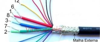
Features of the connecting cable
As a connecting cable, due to the absence of the need to use all contacts, a twisted pair is usually taken, the individual wires of which are soldered to the contacts of the plug and socket of the connector. Due to the rather compact design, it is advisable to additionally insulate the soldering points with cambric or heat-shrink tubing.
The maximum communication range according to the standard should not exceed one and a half tens of meters. If it is necessary to increase it, you should switch to a shielded cable version.