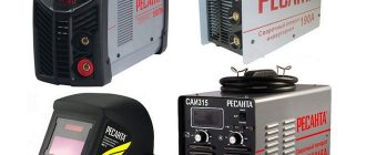
One of the best welding machines of domestic production is the Torus 250. Its distinctive feature is its unique parameters, which foreign analogues and in Russia do not have. The basis for the production of professional welding inverters Torus 250 was laid by Russian scientists and engineers - the founders of arc welding. The country's priority for the invention of electric arc welding using a metal electrode was secured by a domestic patent in 1981 and received in England, France, Germany, Austria, Belgium, Sweden, Italy, and the USA.
Types and features of welding machines Torus 250
The Torus 250 welding machine is professional equipment, produced in 2 varieties - EXTRA and EXTRA (NAKS). It is powered from a 220 V network. It can be used in production and at home, connecting to the power supply through a home outlet. It also works from the mains with drawdowns of up to 165 V and from a gas generator.
Long-term continuous welding with electrodes of 5-6 mm diameter is possible. The power of Torus 250 is enough for remote welding. The maximum permissible length of connected welding wires is 100 m.
Why do welds break?
In the previous post, I was asked to talk about typical malfunctions of RESANTA welding inverters, but I decided that it was better to still tell why welding machines generally break down and then supplement the post with typical malfunctions.
To begin with, I will say that in most cases the welding is broken by the client himself. He does not read the operating conditions and subsequently ruins the device. But there are several main reasons:
1. Reason. Ingress of dust, metal shavings, scale, snow into welding through the cooling system
.
This whole hellish mixture conducts current very well, which subsequently causes a breakdown between the tracks, between the IGBT legs, and at the terminals of the capacitors. There is even a post on this topic (https://pikabu.ru/story/remont_resantyi_250_pn_bumbarabum_60.). Therefore, at least once a year, remove dust from the devices.
2. Reason. Poor nutrition. Weak extension cords, bad sockets, low mains voltage, operation from a generator.
In general, everything that causes a drop in supply voltage.
Due to drawdowns, the current in the primary circuit increases. We have MMA welding and in order to produce, for example, 100A at the output, with a supply of 220V it takes 15A, but when our network is reduced to 120V, then instead of 15A it will take all 25A from the network. All this load is placed on the IGBT transistors, which in turn simply knocks the hell out of them. Therefore, check the voltage drop in the network while the welding inverter is operating.
Design of welding machines Torus 250
In welding inverters, and this is the Torus 250, alternating current is converted into direct current. When the voltage shifts, it becomes possible to increase the strength and frequency of the current. In version 250 of the Torus device, the electrical circuit of the transformations has been modernized and supplemented with electronics. To control the welding process, it uses an electronic board, like a computer.
“Important” The fundamental difference between inverter devices and transformer devices affects power consumption. Welding inverters consume 2 times less electricity. Their welding arc also ensures stable ignition and combustion during welding.
Recent Entries
The customer turned out to be a conscious user, which ultimately saved him a lot of money and speeded up the repair process. When all transistors have been checked and faulty ones have been replaced with good ones, the key module can be conditionally considered working. In this case, automation not only takes into account and smoothes out differences in input voltage, but also corrects even such interference as the attenuation of the welding arc due to strong wind. Diagrams of Svaris devices The Svaris welding machine is characterized by ease of use and low cost. For forging or other repairs, spot welding is used. We pick up Arrange for pick-up of equipment anywhere in Moscow and the region, or bring it yourself to our service stations, “Shchelkovskaya”, “Leninsky”, “Ryazansky”, “Lyubertsy”.
Next, we conduct a secondary inspection and conclude that this device was dropped! The capacitor was replaced and the inverter started working.
Since they are connected in parallel and a resistor is connected to the output, the leakage resistance was about 10 kOhm.
This voltage powers the powerful output stage 2.
Also, the feedback signal from the output stage is fed through current transformer T1 to an overload protection circuit made on thyristor Q3 and transistors Q4 and Q5. RDMMA refers to a new type of equipment that is created without the use of transformers. Only by taking into account the design features can the welding inverter be repaired and fine-tuned. *Under repair!* Inverter "TORUS" (Final)
Specifications
| Modification Torus 250 | EXTRA | EXTRA (NAX) |
| Power supply (V) | 165-242, 50 Hz | 165-242, 50 Hz |
| Open circuit voltage (V) | 65 | 65 |
| Maximum power consumption (kW) | 8.2 | 8.2 |
| Purpose | manual arc welding (MMA) argon arc welding (TIG) | MMA and TIG |
| Welding current range (A) | 40-250 | 40-250 |
| Electrode diameter (mm) | 2020-06-02 00:00:00 | 2020-06-02 00:00:00 |
| Percentage of operating time, duty cycle at 25 °C | 100% at 225 A 60% at 250 A | 100% at 225 A 60% at 250 A |
| Welding current indication | There is | There is |
| Weight | 5.7 kg | 5.7 kg |
| Overall dimensions, mm) | 125*190*330 | 125*190*330 |
“Important” The power of the Extra model is sufficient for household welding work with electrodes with a diameter of up to 3 mm with connection to the mains through a regular outlet.
TORUS-250 modification NAKS is recommended when welding is professional, work is carried out throughout the entire work shift, power reserves are important, and the equipment is required to be mobile and not heavy.
Advantages and disadvantages
First, about the benefits.
- Wide range of applications
The EXTRA inverter is used for arc welding using stick electrodes made of alloy steel alloy, stainless steel, low carbon. It is suitable for use in all sectors of industrial production, housing and communal services and agriculture, car repair services, construction, and everyday life. The device is distinguished by its low weight and compact shape - important characteristics for a welder who often has to move from place to place during work. Suitable for welding external and internal work.
- High-quality weld seam and ease of use
If we talk about the quality of the seam, speed and ease of operation as positive characteristics, then all this applies to inverters of the EXTRA modification. The compact unit can be placed close to the parts to be welded, avoiding the use of long wires. If necessary, the wires can be extended to 100 meters in length.
- Work from an alternative source
Powering equipment from a gas generator has become a significant advantage for residents of rural areas with an unstable power supply. You can switch to operation from a gas generator even in the event of a short circuit, without waiting for troubleshooting in the electrical network.
- Economical
The combination of high efficiency with low power consumption is very attractive when it is important to reduce energy costs.
- High reliability
All devices are assembled from components from leading global manufacturers. The manufactured equipment undergoes multi-stage testing, so the manufacturer is confident in its quality and provides a 3-year guarantee.
Now about the disadvantages. The main disadvantage of EXTRA inverter equipment is its high price. You also need to take care of the wires yourself for welding at a distance from the power source - they are not included in the kit. But this minus is controversial - not all users need them. And for those who do not use remote welding, this is even a plus - you don’t have to pay for something you don’t use.
“Conclusion” The disadvantages have nothing to do with the user characteristics of the unit.
Recommendations for repairing the welding machine “TORUS-200”. Preface.
As I understand from advertising on the Internet, Torus is produced by several manufacturers. The first such device I came across was called “Duga-200” and at the time of writing this article, seven devices of this design have passed through my hands. Externally, the device looks quite civilized, but when you look inside, the guess about its semi-handicraft production involuntarily creeps in. The installation was very sloppy; ordinary screws are used instead of self-tapping screws; the holes do not match well. In addition, varnish insulation, which should be ideal for such devices, is performed extremely poorly or not at all.
The markings of the semiconductor components were destroyed (cut off or filled with a thick layer of opaque resin) and, of course, there was no circuit, so I had to copy the circuit from a non-working device and “decipher” it based on my own knowledge of circuit design and the elemental base of modern power electronics. The diagram may contain errors, but small and unimportant ones.
I assume that this circuit is also suitable for younger Torus models, since in order to reduce the maximum welding current it is enough to reduce the number of switches in the group and the number of diode assemblies or install weaker components. Of course, this is not all, but the rest is unimportant. *** To repair a welding machine, like any other electronic device, it is highly desirable to have some knowledge of electronics and at least minimal repair experience. If you have neither one nor the other, but have a lot of desire and money, then you can try.
The required instruments are an oscilloscope and a dial avometer. It is advisable to solder with an electric soldering iron - a blowtorch is not recommended.
Any repair begins with opening and external inspection of the insides. Structurally, “Torus” consists of the following modules:
- Input rectifier module
- Output rectifier module..
- Key management board.
- Case with fan.
Let's look at everything in order.
Input rectifier module.
The input rectifier is a powerful diode bridge mounted on a radiator, which is attached to the control board from below.
The GBPC3508W bridge is extremely reliable and you have to try harder to burn it. Nevertheless, it is not superfluous to check it. Everyone knows how the bridge rings and nothing new can be invented here. For the inexperienced, we can advise you to unsolder the wires from it, so that in case of a short circuit you do not mislead yourself. It is better to immediately remove the radiator with the bridge from the board to make working with it easier in the future. Key module.
The switch module consists of four groups of four transistors per group. Each group is mounted on a separate radiator on an insulating gasket. In addition to the keys, the module includes six electrolytic capacitors for the smoothing filter of the rectifier that powers the converter (input rectifier).
Most often, a faulty transistor is immediately visible: a cracked or broken case, burnt-out terminals, but sometimes there are no external signs of a malfunction, and then a dial avometer should be used to identify the faulty transistor. We turn it on in resistance measurement mode to the Kom x1 limit and select any group. I think it would be useful to remind you that
all measurements should be carried out with the device turned off from the network .
We measure the resistance between drain and source.
For those who do not know the pinout of the IRFP 460 transistor: if you position the case with the leads down and the markings facing you, then from left to right there will be gate, drain, source
. There is an anti-parallel diode between the drain and the source, and it should ring, i.e. high resistance in one direction, low resistance in the other. A short circuit is a malfunction of one or more transistors in a group, and if there is one, the faulty transistor is detected only by desoldering.
If a group rings as expected (in one direction), this does not always mean that all transistors in the group are working. They need to be checked individually for openability. This can be done without soldering each transistor. First, we unsolder one end of the equalizing resistors from each gate, place the negative probe at the source of the first transistor, and the positive probe at the drain. The tester should show high resistance. Now for a moment we touch the positive probe (without removing the negative one) to the shutter and again transfer it to the drain. The resistance should drop to almost zero and this means that the transistor has opened. Using tweezers or a scalpel, we close the gate with the drain or source and again measure the drain-source resistance, which should increase almost to infinity (but it is more reliable to apply reverse voltage to the gate to turn off the transistor, i.e. minus to the gate, plus to the drain) and this means that the transistor has turned off. If this is the case, we move on to another transistor, otherwise we double-check and bite out the faulty transistor, since this makes it easier to prepare a place for installing a working transistor.
If all transistors in the group are operational, solder the ends of the equalizing resistors to the gates, mark the group as operational and move on to the next group.
When all transistors have been checked and faulty ones have been replaced with good ones, the key module can be conditionally considered working. Conditionally - this is because the final check will be in the presence of control signals.
Recently, switches began to be equipped with snubbers (capacitors soldered between the drain and source of each transistor), which protect the transistors from breakdown.
In this case, the efficiency of the device decreases somewhat, but the reliability increases many times over. When testing the transistors, the capacitors do not need to be unsoldered, because they do not affect the measurement results. Output rectifier module.
The output rectifier module consists of a board with two radiators on which power diode assemblies are mounted. Depending on the assemblies used, their number on the radiator may be different - two or four. The module also includes a choke and a transformer.
Diode assemblies of the output rectifier rarely fail. The two-hundredth model uses two 60CPQ150 or four 30CPQ150 assemblies, and each assembly has two diodes of 60 and 30 amperes (respectively) of maximum current each. That's a total of 240 amps DC. A reserve of 40 amperes is quite reliable, and the maximum pulse current is almost an order of magnitude greater.
Everyone knows how diodes ring. If the group rings short, you need to look for a broken diode. You can't do without desoldering, and for this it is convenient to use a soldering iron with suction.
When all diodes have been checked and faulty ones have been replaced, the module can be marked as good and we can begin checking the control board.
Key management board.
The key control board is the most complex of all units of the device, and the reliability of the device and the integrity of its components depend on its correct operation.
A preliminary check of the operation of the control board can be done without dismantling it, i.e. right on the spot. First of all, we turn off the power to the converter, for which we unsolder one of the thick wires coming from the control board (220V AC) from the input bridge and insulate its bare end with electrical tape.
Since to assess the performance of the control board it is necessary to evaluate rapidly changing signals, you cannot do without an oscilloscope (and the skill of working with it).
We insert the power plug into the socket and listen carefully. The fan rotates and after 3-5 seconds a click is heard. It is produced by the relay of the “soft” switching circuit. If there is no click or it is heard immediately after switching on, then the “soft” switching circuit is faulty. Also, if there is no click, it is worth checking the presence of +15V supply voltage. The source of this power is glued to the control board and soldered to it with four wires: two of which are 220V AC and the other two are plus and minus 15V. If there is no power, we dismantle the power supply and repair or replace it, since it is standard.
The “soft” switching circuit is very simple and is based on the activation of em. relay K2 as a result of the opening of transistor VT5 after charging capacitor C22 in its base circuit. Relay contacts S3 short-circuit resistor R40, which extinguishes the charging current of the input rectifier filter capacitors. This resistor is very weak and often fails. I replace this resistor, even if it is working, with a more powerful one to increase the reliability of the device. The absence of a relay response delay can be caused by a break in the charge capacity C22, a breakdown of the transistor VT5 and a breakdown of the dinistor analogue VD4 in the transistor base circuit. Next, we check for the presence of key control signals. These signals are sent via four twisted pairs of wires to the gate buses of the key module. We set the oscilloscope sweep to 5 µs/div, and the attenuator to 5 or 2v/div. We connect the common wire of the oscilloscope to the common wire of the control board (occupies a noticeable part of the front side area), and use a probe to check the signals on legs 1 and 7 of the DD2 and DD3 microcircuits. Normally, there should be rectangular pulses with a rounded front with an amplitude of about 15 V and a frequency of about 100 KHz. If there are pulses, you should check their passage to each gate.
If the device has been in someone’s “skillful” hands before, it’s a good idea to check the phasing of the control signals: if the twisted pairs are reversed, then there is a risk of running into a through current, and if the wires in the pair are reversed, the key will not open. I came across devices literally “plowed” by “craftsmen” and these devices had to be checked thoroughly. The situation is further complicated by the fact that the assembly quality of the devices is semi-handicraft and it is not always possible to distinguish the soldering of the manufacturer from the soldering of the “craftsman”.
For those uninformed, I can clarify: the gate should receive positive (relative to the source) pulses with an amplitude of about 15V. At the same time, groups 1 and 4 should open in one measure and 2 and 3 in another measure. Signal in-phase can be determined using a two-channel oscilloscope.
If the control signals from the control board arrive at each gate with the required amplitude and in the required phase, you can try to turn on the device. In order to insure against the consequences of an undetected malfunction, we turn on the power of the converter through a 150-200 W incandescent lamp - it is more convenient to connect it to the alternating circuit of the input rectifier bridge. We solder all the wires that were previously soldered taking into account the lamp and turn on the device into the network and look at the lamp. At the first moment, the lamp may flash brightly (the filter capacities are charging), but it should glow faintly all the time. A bright glow indicates a short circuit in the circuit or load circuit. .When all the faults are eliminated, unsolder the lamp, solder the power wire to the bridge and turn on the device to the network. We measure the voltage at the output terminals - the normal voltage level should be about 60 DC volts.
*** In the case when the control board does not produce triggering pulses, for ease of operation it is better to separate it from all nodes, i.e. unsolder the twisted pairs from the keys, having previously marked the groups and wires, unsolder the overheating sensors and insulate the ends of the wires, unsolder and disconnect the input rectifier bridge, unsolder the power cord.
Next, solder the power cord, preferably through a 50-100W light bulb, and plug it into a power outlet. First of all, you should check the presence of +15V power on pins 3,6,9 of microcircuits DD2 and DD3 and rectangular clock pulses on pins 10 and 12 of the same microcircuits. A couple of times I encountered the burnout of a resistor in the DD3 power circuit, although after that the microcircuit itself had to be replaced. If there are clock pulses on legs 10 and 12 (i.e., at the inputs), but there are no pulses on legs 1 and 7 (i.e., at the outputs), leg 11 needs to be connected to the common wire, and if the microcircuit is working properly, the pulses at the outputs should to appear. There are no pulses - feel free to replace the microcircuit. In normal condition, leg 11 of microcircuits DD2 and DD3 may not have an exact zero (i.e., the microcircuit is closed) and to check whether the microcircuit is faulty or closed, you need to apply an exact zero to leg 11.
If the driver inputs (DD2 and DD3) do not receive clock pulses, then they need to be looked for at pins 9 and 10 of the PWM chip - DD4. If they are absent, check the +15V power supply at pins 8, 11, 12. You can check whether the red indicator on the front panel of the device is lit, and if so, then the operating mode toggle switch is most likely turned off. You can also check whether one of the two overheating sensors is shorted (on the output rectifier radiator and on the inductor). If all efforts are in vain, we replace the microcircuit.
You have achieved control pulses at the outputs of both drivers.
It would seem that this is happiness, but this happiness may be followed by fireworks when you try to light an arc. The fact is that there is also a current regulation and current protection circuit, and if this protection does not work, then you risk going to the second round of troubleshooting. The adjustment and protection circuit is implemented on the DD1 chip and its wiring. The current sensor is a ring coil L1 through which the thick power wire of the converter passes. At pins 1 and 7 of the DD1 microcircuit, rectangular driver closing pulses are formed. You can check the operation of the circuit in different ways. I use the following: I unsolder one end of the L1 coil and solder a 3V AC voltage source instead. This could be a transformer from a power adapter or something original. I supply 3V variables and watch the signals at pins 1 and 7 of the DD1 microcircuit - short rectangular pulses with a frequency of 50Hz. At the same time, the ring transformers emit quiet sounds (vaguely reminiscent of the voice of a grasshopper), and the triggering pulses are interrupted at a frequency of 50 Hz. April 2009 V.A. Tretyakov
Operating principle of welding machines Torus 250
Topyc 250 inverters, like the entire Torus line, are easy to use. They have a special knob to adjust the current. To notify the user whether the equipment is turned on or not, a light indicator is used - the welder is informed in red that the device is turned off or overheated. Green indicates that the unit is operational.
After making sure that the device is turned off, cables are connected to it, and the working parts are grounded. Then an electrode with an electrode holder is prepared for manual arc welding, and the device is connected to the network. The green and red indicators should light up and the fan should turn on.
Then the switch is moved to position “1”, the red indicator should go out. The device is ready for use, parts can be welded. To weld metals, an electrode is touched to the site of the planned seam and the arc is ignited. By turning a special knob, the welding current is adjusted to the desired value.
Recommendations for working with devices
- Preparing the unit for operation should begin by checking the condition of the wires, contacts, and terminals. It is recommended to pay attention to their condition during welding.
- When the unit has turned off in automatic mode, as indicated by the red indicator, it does not need to be turned on immediately. The device must be given time to cool down.
- The unit must be handled with care, not dropped or subjected to mechanical impacts.
- It is not recommended to operate the device in rooms with a high degree of dust.
- Due to the formation of condensation, there are restrictions on operation at sub-zero temperatures.
- After finishing work, there is no need to rush to disconnect the unit from the power supply. You need to wait a few minutes, giving the fan time to idle. This will extend the time before repairing the fan and its lifespan.
- It is not recommended to leave the electrodes in the holder for a long time unnecessarily.
- Do not use adjustable wrenches when removing electrodes.
If repairs are made independently, rather than at a Torus equipment service center, the user loses warranty service.
