Gear wheels have become very widespread. Their main purpose is to transmit force or rotation. As a rule, such an element is engaged at the time of operation. Spur gears are characterized by quite a large number of features that must be taken into account. For example, the length of the common normal of a gear can vary over a fairly large range. Let's look at this indicator in more detail.
Calculation of the length of the common normal of a gear
To check the quality of manufacturing of the surfaces of the teeth of involute cylindrical wheels, two types of control are very widely used in practice: measuring the size by rollers (balls) and measuring the length of the common normal.
The measured values are compared with. . values calculated by the designer, which he is obliged to indicate in the table on the detail drawings of the gear and gear. Since to measure the length of the common normal it is enough to have only a caliper, this method of monitoring the thickness of the teeth is practically more accessible and is widely used especially in the single (repair) production of cylindrical gears of low accuracy. It should be noted that this control method is quite accurate due to the direct method of measuring the part, as opposed to measuring the size using rollers, which introduce additional error with their tolerances. The length of the common normal refers to the parameters characterizing the norm of the lateral clearance in the gear drive.
Let's calculate the length of the common normal in Excel.
If you do not have MS Excel on your computer, you can perform the calculation in Calc from the free Open Office package.
We consider the external
engagement! The calculation is regulated by GOST 16532-70. The measurement diagram is shown below in the figure. Measurements are taken in the plane of the normal (perpendicular) surface of the teeth. For helical wheels (especially at large angles of inclination), after calculations it is necessary to make sure that the width of the wheel crown is “enough” to carry out the measurement.
Let's start the calculation. We write the initial data in cells with a light turquoise fill, and read the calculation results in cells with a light yellow fill. Traditionally, cells with a light green fill contain source data that is less susceptible to change.
Fill in the initial data:
1. Engagement module m
we write in millimeters
to cell D3: 8,000
2. Number of teeth z
, controlled wheel we write down
to cell D4: 27,000
3. the angle of inclination of the gear teeth b in degrees
to cell D5: 17,2342
4. Enter the displacement coefficient of the original contour x
to cell D6: 0,350
5. Write down the profile angle of the normal initial contour a
to cell D7: 20,000
Next, the calculation in
Excel is performed automatically - we find two auxiliary and two main required parameters:
6. the profile angle at in degrees
in cell D9: =ATAN (TAN (D7/180*PI())/COS (D5/180*PI()))/PI()*180 =20.861
at =arctg(tg(a)/cos(b))
7. We calculate the conditional number of wheel teeth zk
in cell D10: =D4*(TAN (D9/180*PI()) -D9/180*PI())/(TAN (D7/180*PI()) -D7/180*PI()) =30,777
zk = z *(tg ( at ) - at )/(tg ( a ) - a )
8. Read the number of teeth in the length of the common normal zn
in cell D11: =ROUND(0.5+D10*ACOS (D10*COS (D7/180*PI())/(D10+2*D6))/PI();0) =4,000
zn =0.5+ zk * arcos ( zk * cos ( a )/( zk +2* x ))/π rounded to the nearest integer
9. The length of the common normal W in millimeters is calculated
in cell D12: =D3*((PI()*D11-PI()/2+(TAN (D7/180*PI()) -D7/180*PI())*OCRVDOWN(D10;1))* COS (D7/180*PI())+0.014*(D10-OCRVDOWN(D10;1))+0.684*D6) =88,023
W = m *((π* zn -π/2+(tg ( a ) — a )* zk' )*cos ( a )+0.014*( zk — zk' )+0.684* x )
Here zk '
-integer part from
zk
(“rounding down”).
So, further in our example, we must take a caliper, measure the length of the common normal of four teeth (several times and different groups) and obtain values equal to the calculated value for a high-quality cut wheel.
In fairness, it is necessary to mention that to measure the length of the common normal, there is a special tool - a normal gauge. The normal gauge is made on the basis of a caliper or micrometer, supplying the latter with special jaws and a dial indicator that are convenient for performing measurements.
Tolerances of cylindrical gears are regulated by GOST1643-81. In particular, tolerances are assigned to the length of the common normal depending on the type of mating and the standard of lateral clearance.
I'll grumble a little. In reference books and in GOST, the above calculation is written in such a way that “you need to deal with beer for two days, “jumping” from table to table.” Apparently this was always done in such cases by the authors to give themselves “the highest importance and significance”... And ordinary students and engineers need to be “intimidated” by the abundance of transitions from page to page, so that on the fourth or fifth transition to a new table or diagram they forget that generally do. If, at the end of everything, we add something completely terrible - like an involute (these are not euros or dollars, but this is the function), then that’s it - the job will be done. For every hundred mechanical engineers, let's get one or two who understand a little about gears! And if you get into the jungle of contour displacement to obtain certain power or quality changes, you find out that in Germany and Japan they first calculate and optimize the transmission, and then make a tool for it... And we still calculate everything using a standardized tool - a = 20 degrees ...
The topic of gears, begun in the article “Calculation of gears,” will certainly be continued. Follow the announcements.
About control dimensions of gears and side clearance
A little about methods for measuring tooth thickness.
Most gear drives require side clearance to operate properly. In gears with adjustable axles, the gap can be adjusted by changing the center distance. In gears with a constant center distance, the clearance is provided when cutting the wheel teeth. To do this, a tolerance field with two minuses is set for the parameter characterizing the tooth thickness. Thus, a certain gap between j nmin teeth is guaranteed in the transmission. The magnitude of the side clearance and the tolerance for the side clearance (tooth thickness) are specified in the form of a mate (A, B, C, D, E, H). A is the roughest type of mating, H is the most precise type of mating (the minimum guaranteed gap is zero). The type of coupling is indicated in the degree of accuracy of the wheel (for example, 8-B)
There are several different geometric parameters that can be used to express the thickness of the tooth and therefore the lateral clearance in the gear:
- tooth thickness along the chord S c ;
- common normal length W ;
- ball size M ;
- displacement of the original contour E H ;
- interaxle distance in backlash-free engagement with the reference wheel;
These parameters within one wheel are connected by strict geometric relationships. Those. Knowing one parameter, you can calculate any other. I will not give formulas here. All the required calculations are in GOST 16532-70 “Cylindrical involute gear transmissions of external gearing. Calculation of geometry" and in various programs.
According to GOST 1643-81 Basic standards of interchangeability. Cylindrical gear transmissions. The tolerances of all measurement methods are equal to each other, therefore the wheel manufacturer has every right to use for control not the parameter indicated in the drawing, but another, if he guarantees the measurement with the required accuracy.
The tolerance values in the standards are also related to each other, i.e. To achieve the same specified clearance, the wheel manufacturer may use different measurement methods. All methods have their advantages and disadvantages, and I will try to talk about them briefly and the benefits of using each of them. To measure each parameter, there are devices of various designs, but as an example I will give examples of overhead devices that can be used directly when cutting a gear without removing it from the machine.
The deviation of each size is specified by two values: the smallest deviation (corresponds to the upper limit of the tolerance field, i.e. the minimum gap in the gear) and the size tolerance (corresponds to the lower limit of the tolerance field, i.e. the maximum gap in the transmission)
- for the tooth thickness along the chord, the smallest deviation of the tooth thickness E cs and the tolerance for the tooth thickness T c (see GOST 1643 tables 20, 21)
- for the length of the common normal, the smallest deviation of the average length of the common normal E Wms and the tolerance for the average length of the common normal T Wm (see GOST 1643 Tables 16, 17,18). “Average” here means that the control evaluates the arithmetic average of several measurements on different gear teeth.
- for the ball size, the tolerance is determined by recalculating the tolerances for the length of the common normal E Wms and T Wm (for calculation, see GOST 1643, paragraph 3.7)
- to shift the original contour, set the smallest additional displacement of the original contour E H and the tolerance for the displacement of the original contour T H (see GOST 1643, tables 14, 15).
Chord thickness.
Measuring tooth thickness along the chord is the most common measurement method in practice. The essence of the method is to measure the length of the chord between the left and right sides of the tooth at a given height. Of course, tooth thickness can be measured in an infinite number of places along the height of the tooth, but in practice, in most cases, tooth thickness is measured along a constant chord. For measurements, special instruments are used - chordal tooth gauges (vernier tooth gauges and indicator tooth gauges)
Advantages:
- the value does not depend on the number of teeth and the angle of inclination of the wheel and is calculated using fairly simple formulas.
- several measurements. made in different places of the wheel, allow one to evaluate the radial runout of the wheel and the corresponding fluctuation in the gear gap.
Flaws:
- The gear gauge is based on the tops of the wheel teeth, i.e. for accurate measurements, you need to calculate the installation height of the device taking into account the actual diameter of the vertices or process the diameter of the vertices with a tolerance that guarantees a sufficiently accurate measurement;
- the gear gauge comes into contact with the edges of the wheel being measured, this leads to faster wear of the tool and a decrease in measurement accuracy;
- In the case of a caliper, the measurement accuracy, like any caliper, is limited. The measurement error is usually no better than 0.05-0.1 mm.
When cutting a wheel on a gear hobbing machine, by measuring the constant chord, you can calculate the required radial feed for infeed:
plunging feed = chord thickness change / sin( 2 * engagement angle α)
with a standard initial contour with engagement angle α=20°:
plunging feed = 1.556 * chord thickness change
Offset of the original contour.
An overhead device for measuring displacement is called a displacement gear gauge.
The jaws of the device have the shape of a recess. The device is adjusted using rollers (each module has its own diameter). The adjusted device imitates the depression of the rack in engagement with the wheel having the theoretical diameter of the vertices. The indicator resting on the top of the tooth shows the displacement of the rack in the radial direction, i.e. The reading of the device is proportional to the radial feed of the hob cutter when processing on a gear hobbing machine. As the tooth thickness decreases, the instrument moves closer to the tooth cavity and the instrument needle moves to “+”. In general, offset measurement has the same advantages and disadvantages as chord thickness measurement.
Length of the common normal (size in girth).
To explain what the length of the common normal is, we can use the analogy of a thread and a spool. Let's imagine that one thread unwinds the left involute, and the other the right involute. At some point, both threads will lie on the same straight line and touch the spool at the same point. The length of the segment between the sides of the tooth will be the length of the common normal. Theoretically, for measurement, you can take a segment between any pair of teeth intersected by this straight line, but in practice, only those segments that intersect the actual cut surface of the tooth are suitable for measurement. If you calculate the number of teeth in the girth using the formula from GOST 16532-70, then the device will touch the teeth at points as close as possible to the pitch diameter.
Advantages:
- measurement is carried out with simple instruments (normal gauge, caliper, micrometric normal gauge). It is quite simple to calibrate the device using a standard wheel or a set of gauge blocks;
- the measurement does not require any bases. The basing occurs directly on the involute surfaces of the teeth;
- the device does not have edge contact with the wheel being measured, the measuring surfaces wear out less;
- the length of the common normal is measured along the line of contact of the wheels in engagement, i.e. the sum of the deviations of the two wheels will be equal to the gap in the pair (without taking into account radial runout and other errors);
- By measuring the general normal, the fundamental pitch of the wheel can be calculated. This can help in determining the module and angle of engagement of the wheel, when setting up the machine, and in assessing the accuracy of the gear cutting tool.
Overall this is the most accurate measurement method.
Flaws:
- when measuring narrow multi-toothed wheels, sometimes the width of the wheel is not enough to cover the required number of teeth;
- when cutting with a hob cutter on a gear hobbing machine, measuring the general normal does not reveal the radial runout of the wheel. In this case, it may be necessary to additionally check the radial runout of the ring (for example, using a ball, roller, or using a special device;
When cutting a wheel on a gear hobbing machine, by measuring the length of the common normal, you can calculate the required radial feed for infeed:
infeed = changes in common normal length / (2 * sin (engagement angle α))
with a standard initial contour with engagement angle α=20°:
plunging feed = 1.462 * changes in the length of the common normal
Size by balls (rollers)
This method measures the distance between the extreme points of balls or rollers inserted into opposite cavities of the wheel. When measuring helical gears, balls are used, because... The contact of the roller with the opposite sides of the cavity does not occur in parallel lines and the roller will swing in the cavity. According to GOST, it is recommended to take the diameter of the ball (roller) = 1.7 * module. With this diameter, the balls (rollers) will contact the tooth surfaces close to the pitch diameter.
To measure spur gears, rollers, balls and measuring wires are used in accordance with GOST 2475-88 Wires and rollers. Specifications
balls are used to measure helical gears
Advantages:
- measurements are carried out with universal instruments for measuring lengths (calipers, micrometer) and balls/rollers whose diameter can be quite easily controlled;
- convenient to measure small-module wheels;
- the measurement does not require any bases. The basing occurs directly on the involute surfaces of the teeth;
- the measurement possibility is not limited by the geometric parameters of the wheel.
Flaws:
- the measurement result is influenced by the accuracy of the tooth profile;
- the measurement shows the arithmetic mean of the thicknesses of opposing teeth, i.e. does not fully detect the radial runout of the crown
________________________
Useful links on dental processing
On the issue of involute.
Gears and Reverse engineering.
On the issue of gear alignment, a little about runout and contact patch
Modified on December 26, 2011 by tmpr
We calculate the length of the common normal using the formula
W = m × W1,
where W1 is the length of the common normal for the gear at m = 1 mm [2].
W =1.25 ∙ 10.7246= 53.623 µm.
We select the smallest deviation of the length of the general normal Еws according to the GOST 1643-81 table. Еws = -25 µm.
The largest deviation of the length of the general normal Ewe is determined by the formula:
where Tw is the tolerance for the length of the common normal, determined according to the GOST 1643-81 table based on the radial runout tolerance Fr, which is selected according to Table 6 depending on the degree of kinematic accuracy (Fr = 36 μm).
Ewi = –25 – 40 = -65 µm.
Then the length of the common normal in the drawing of the gear will look like
Tolerances for the dimensions and locations of the base surfaces of the wheel are assigned taking into account the selected indicators of control of the ring gear.
Since the outer surface of the gear is not used as a base surface (measuring and setting), the tolerance for the outer diameter Tda is assigned as for non-mating dimensions - h14, and the radial runout of the outer surface is determined by the formula [2]:
The tolerance for axial runout of the base end is determined by the formula [2]
where Fb is the tolerance for the error of tooth direction according to the degree of contact completeness norm mm;
B – width of the ring gear mm;
D – diameter at which runout is determined
d = (z1-2.4)∙m =(12 - 2.4) ∙5 = 48 mm
The accuracy of the base hole according to [2], depending on the degree of accuracy of the gear 7, will be H7. The roughness of the working surface of the teeth is determined based on the degree of accuracy in terms of smooth operation Ra = 3.2 µm.
Task 9. Calculation of dimensional tolerances included in the dimensional chain
-
increasing size - decreasing size
-
closing link
Closing link tolerance
Average number of tolerance units
Let's find the number of tolerance units
We choose IT = 10, at which a = 64
Let us determine the tolerances for the links of the dimensional chain:
It follows that all parts are performed according to the 10th accuracy level.
Conclusion
As a result of completing the course work, the skills of calculating and assigning interference fits, calculating the calibers of plugs and brackets for controlling the hole and shaft, calculating and selecting fits for rolling bearing rings, determining the dimensions and tolerances of connection elements for keyed connections, determining nominal and limiting dimensions for all thread diameters for a given threaded connection, determining the numerical values of controlled indicators of accuracy standards and the amount of lateral clearance required for the normal operation of a given gear train, calculating the dimensional chain for a given value of the closing link.
All calculations were carried out using state standards, educational and reference literature.
The acquired skill is the basis for further engineering activities
Bibliography
1 A. P. Martynov, L. N. Abramova “Methodological instructions for completing coursework for students of all specialties in the discipline “Engineering Mechanics” on the topic “Limit gauges for testing surfaces” Kramatorsk 2000.
2. Tolerances and landings: A reference book in 2 parts / Ed. V.D. Myagkova. – 5th ed., revised. and additional - L.: Mechanical Engineering, 1978. – 544 p.
3. E.V.Perevoznikova, M.P.Khudyakov. Metrology, standardization, certification. Tutorial. Part 1 "Metrology". Severodvinsk. Sevmashvtuz, 2007. – 88 p.
4. GOST 24853-81 “Smooth gauges for sizes up to 500. Tolerances”
5. GOST 25347-82 “Geometric characteristics of products. Ranges of tolerances, maximum deviations of holes and shafts.”
1.3. Tolerances for measuring dimensions of cylindrical gears
The formulas discussed above for calculating the nominal measuring dimensions of cylindrical gears guarantee backlash-free engagement of the wheels in the gear. In real gears, guaranteed lateral clearance
in order to eliminate jamming of teeth when operating under load as a result of thermal deformation of transmission parts, as well as to place a layer of lubricant on the working profiles of the teeth.
The lateral clearance in the meshing is also necessary to compensate for errors in the manufacture and installation of the gear. It is determined mainly by the value of the axle distance a w
of the gear and the thickness
s of
the wheel teeth.
The standard for involute gear cylindrical gears (GOST 1643-81) establishes eight types of tolerances for lateral clearance: h
,
d
,
c
,
b
,
a
,
z
,
y
,
x
(tolerance designations are arranged in ascending order of tolerance).
The accepted value of the guaranteed lateral clearance is the basis for assigning the type of
gear mating.
The same standard provides for six types of mating: H
- zero gap,
E
- small gap,
C
and
D
- reduced gap,
B
- normal gap,
A
- increased gap.
Matings of types H
,
E
and
C
require increased precision in the manufacture of wheel teeth.
They are used for reversible gears with high requirements for kinematic transmission accuracy, as well as in the presence of torsional vibrations of the transmission shafts. Most often in average mechanical engineering, gears with coupling types B
and
C
.
In the absence of special requirements for the gear drive, with each type of mating, a certain type of lateral clearance tolerance is used, denoted by a lowercase letter similar to the letter of the mating type (for example, A
-
a
,
B
-
b
,
C
-
c
, etc.).
The tolerance field for the measuring size of a gear is always directed towards the tooth body, therefore the maximum deviations of the measuring size (upper and lower) always have negative values [1].
Length of the common normal of the gear
Gear wheels have become very widespread. Their main purpose is to transmit force or rotation. As a rule, such an element is engaged at the time of operation. Spur gears are characterized by quite a large number of features that must be taken into account. For example, the length of the common normal of a gear can vary over a fairly large range. Let's look at this indicator in more detail.
What is the length of the common normal?
To ensure the functioning of the mechanism represented by gears, the main indicators are measured using two methods, one of which involves the use of rollers, the second is determining the length of the common normal. When considering the normal, you should pay attention to the following points:
- Almost all cylindrical involute gears of external gearing and other types are produced taking into account the considered indicator.
- The length is determined by the distance between opposite sides of the same cavity.
- This indicator depends on the diameters of the gears, as well as some other parameters.
Measurement principles
As previously noted, measurement of the gear normal is carried out to determine the workmanship of the product in question. Among the features of the measurement procedure, the following points can be noted:
- In most cases, only one measuring device is needed to obtain the required data - a caliper. It is characterized by relatively high accuracy and low cost, and is found in many production sites. After obtaining the required data, you can calculate the length of the general normal of the gear.
- The considered method for determining the total length of the normal has become widespread due to its availability. However, only products with a relatively low degree of accuracy can be checked.
- It is worth considering that size calculations based on rollers are not carried out due to the relatively low accuracy.
The length of the general normal of the helical gear is calculated due to the fact that a similar indicator is used when determining the standard of lateral clearance when creating a gear drive.
Mechanisms with external gearing have become quite widespread. GOST 16532-70 gear calculations are performed in the plane of the normal tooth surface. In addition, with an oblique position of the tooth, after calculations, attention is paid to ensuring that the width of the wheel rim allows the required measurements to be taken.
Download GOST 16532-70
When performing calculations, you can use not only formulas, but also special programs. A fairly common type of such program is a table made in Excel. As a rule, the table provides for entering the following information:
- Engagement module. This indicator is considered one of the main ones and is calculated at the time of design. As a rule, it is indicated in the table with the letter “m”.
- Number of teeth. This parameter is also decisive. It can vary over a fairly large range. In the table and technical documentation, indicators are designated by the letter
- Tilt angle. This value is measured in degrees, indicated by the letter b.
- Main contour displacement coefficient (x).
- Profile angle of the normal original contour.
After filling out this information, you can calculate the tolerance for the length of the general normal of the gear and many other important indicators that are taken into account during the design.
Software of this type has become quite widespread due to the fact that it is easy to use and can be installed on a smartphone or other mobile device. Entering data is quite simple; the program calculates a variety of indicators that are required in production. Typically, it is required to determine the following values:
- Profile angle.
- Conventional number of wheel teeth.
- Number of teeth in the length of the common normal.
- Lengths of the common normal.
The KOMPAS-3D program has become very widespread in the design field. It is used to obtain drawings of various types; basic indicators are also calculated automatically. A library called “Shafts and mechanical transmissions 2D” can be used for work. In this case, the calculation is carried out automatically, which reduces the likelihood of errors.
It is possible to carry out calculations using conventional formulas. They are as follows:
The first formula is suitable for determining the length of the common normal of spur gears without displacement, the second for versions with displacement. W1 refers to the length of the common normal of the cylindrical wheels. It is worth considering that such an indicator depends on the number of teeth of the entire wheel, as well as the number of teeth that are covered during the measurement.
Do not forget that when carrying out the calculations under consideration, tabular data is required. Such tables indicate the following information:
- Total number of wheel teeth.
- The number of teeth that are covered when taking measurements.
From this documentation you can find out the required data for performing various calculations.
Helical cylindrical wheels have become quite widespread. They are required in case of crossed shafts. The mechanisms under consideration retain the established dependence; another important parameter is the interaxial angle.
Such design options are not recommended for transmission of rotation, as they are characterized by low efficiency. This is why other mechanisms with spur gears should be considered.
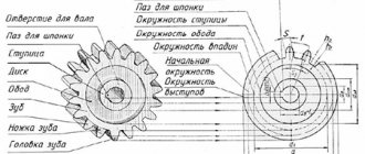
Involute gearing of internal gearing is also widely used. The main elements of this version can be called the following:
- Tooth.
- Depression.
- Ring gear.
- Surface of peaks and valleys.
A fairly large number of different tables are used when calculating the main parameters. That is why, when developing a project, you should be guided by various regulatory documentation.
Classification of gears and accuracy requirements for them.
Gears and gears are classified according to various criteria:
- by the type of surfaces on which the teeth are located (cylindrical and conical, internal and external),
- in the direction of the teeth (straight, helical, helical, chevron),
- according to the profile of the teeth (involute, cycloidal, clockwise, lantern, Novikova),
- in the direction of the axes of rotation (cylindrical - with parallel axes, conical - with intersecting, screw and worm - with intersecting).
- by design : open (unframed) and closed (framed);
- by circumferential speed : low-speed (up to 3 m/s), for medium speeds (3-15 m/s), high-speed (over 15 m/s);
- by number of stages : single- and multi-stage;
- according to the arrangement of teeth in the gear and wheels : external and internal;
- according to the relative mobility of the geometric axes of gear wheels : with fixed wheel axes - ordinary gears; with movable axles of some wheels - planetary gears.
- in terms of meshing accuracy . The standard provides 12 degrees of accuracy.
- By purpose they are distinguished : power transmissions intended for transmitting power; kinematic transmissions, that is, transmissions that do not transmit significant power, but perform purely kinematic functions.
The basis for the classification is not limited to the examples given. Among the many classifications, the most important for selecting accuracy parameters are those that determine the functional purpose of the transmission.
Gear transmission with cylindrical wheels: a - spur; b - helical; c - chevron; g - conical; d - with a circular tooth; e - with internal gearing.
The requirements for the accuracy of gears depend on the functional purpose of the gears and their operating conditions.
In instruments, dividing machines, in technological equipment for cutting threads and gears, so-called “counting gears” (in which the main attention is paid to the proportionality of the angles of rotation of gear wheels (kinematic transmission accuracy). The wheels of these gears in most cases have a small modulus and operate at light loads and low speeds.
“Power” or heavily loaded gears, in which high demands are not placed on the accuracy of wheel rotation (gears in jacks, winches, presses, etc.).
In gearboxes of turbines and high-speed engines, and in other products with high rotational speed, “high-speed gears” (high-speed, high-speed gears) are used, for which the main requirements are for smooth operation, which is necessary to reduce the level of vibration and noise during product operation.
If gears do not have a clearly defined operational character, they are classified as general-purpose gears. Such transmissions are not subject to increased accuracy requirements.
Norms and degrees of accuracy of gears and gears.
- kinematic accuracy standards;
- standards for smooth operation;
- contact standards;
- side clearance standards.
Norms of kinematic accuracy. Requirements have been established for the parameters of wheels and gears, which affect the inaccuracy of transmission for a full revolution of the wheel, i.e. this is the error in the angle of rotation of the wheel per 1 full revolution compared to if instead there are absolutely accurate wheels.
Most important:
- in dividing mechanisms
- when applying and practicing circular divisions
Smoothness standards: refer to pairs of gears, associated with kinematic accuracy and appear many times during one revolution of the wheel. One or more times on the entire tooth, highest value
- works at high speeds
- no noise or vibration
Standards for tooth contact: requirements are established for those parameters that determine the size of the surface of the tangent teeth of mating wheels
Particularly important:
for heavily loaded gears
Side clearance standards: establish requirements for wheel parameters that affect the amount of clearance along an idle profile in contact with operating profiles.
The standard standardizes uniform accuracy series for normalizing kinematics, smoothness and tooth contact.
GOST 1643 - 81 allows you to set twelve degrees of accuracy of cylindrical gears and gears - from 1 to 12 in descending order of accuracy.
Currently, tolerances and maximum deviations of the parameters of gears and gears are normalized for degrees of accuracy 3...12, and degrees 1 and 2 are provided as promising.
For each gear (and gear), accuracy standards (degrees of accuracy) of three types are established, which determine the degrees of kinematic accuracy, smooth operation and tooth contact.
Regardless of the degree of accuracy, types of mates are established that determine the requirements for the lateral clearance.
GOST establishes for gears and gears with a module greater than 1 mm six types of mates (A, B, C, D, E, H) and eight types of tolerance (a, b, c, d, h, x, y, z) guaranteed side clearance jnmin
Designation of the accuracy of gears and gears.
7 – C GOST 1643-81 – cylindrical gear with degree of accuracy 7 according to all three standards, with gear mating C and correspondence between the mating type and the class of deviations of the center distance;
8 – 7 – 6 – Va GOST 1643-81 – cylindrical gear with degree of accuracy 8 according to kinematic accuracy standards, with degree 7 according to smoothness standards, with degree 6 according to tooth contact standards, with mating type B , type of tolerance for lateral clearance a and correspondence between the type of mating and the class of deviations of the interaxial distance;
7 – 600y – GOST 1643-81 – transmission 7th degree of accuracy with a guaranteed side clearance of 600 microns (not corresponding to any of the six types of mates) and a tolerance for the side clearance of type y ;
7 – Ca /V- 128 GOST 1643-81 – transmission with degree of accuracy 7 according to all standards, with wheel mating type C , side clearance tolerance type a and a coarser class of center distance deviations – V and reduced side clearance of 128 microns .
Accuracy indicators of gears and gears. Main indicators of kinematic accuracy
The kinematic accuracy of wheels is most fully revealed when measuring the kinematic error or the accumulated pitch error of the gear wheel, which are complex indicators.
Instead of these parameters, private parameters can be used (radial runout of the ring gear and fluctuation in the length of the common normal).
The runout of the working axis of the gear cutting machine and the inaccuracy of the installation of the wheel blank relative to this axis cause the appearance of a radial component of the kinematic error.
The tangential component of the kinematic error is associated with errors in the angular (“dividing”) kinematic movements of the elements of the gear cutting machine.
Basic indicators of smoothness
Indicators of smoothness are deviations of the pitch of the gear teeth and deviations of the meshing pitch from the nominal values, as well as errors in the tooth profile.
The deviation of the (face) pitch of the teeth of a gear wheel is understood as the difference between the actual pitch and the calculated face pitch of the gear wheel.
The actual pitch of engagement is understood as the distance between parallel planes tangent to two active lateral surfaces of the same name of adjacent gear teeth.
Tooth profile error is the normal distance between two nominal end profiles closest to each other, between which the actual end profile is located on the active section of the gear tooth.
Main indicators of contact completeness
The completeness of contact of the working surfaces of the teeth is assessed by the contact patch (integral contact indicator) or by private indicators.
To control the contact patch, the side surface of the smaller or measuring wheel is coated with paint (minimum lead or Prussian blue is used), and the layer thickness does not exceed (4...6) microns, and the wheels are run in with light braking. The dimensions of the contact patch are determined in relative units - percentages of the length and height of the active surface of the tooth. When assessing the absolute length of the contact patch, the gaps in the patch are subtracted from the total length (in millimeters) if they exceed the value of the gear module.
Assessment of the accuracy of the contact of the lateral surface of the teeth in the gear can be carried out by separate control of the elements that affect the longitudinal and height contacts of the gear teeth.
Basic indicators of the gap between the non-working side surfaces of the teeth
The following can be used as indicators of the gap between the side surfaces of the teeth for a gear:
- interaxle distance, determined by the size of the tooth of the controlled wheel during complex control in backlash-free engagement with the measuring wheel;
- thickness of the tooth along the chord at a given distance from the circumference of the protrusions;
- the length of the common normal, the value of which depends on the thickness of the tooth;
- roller size M , determined by the displacement of the original contour.
Monitoring the accuracy of gears and gears. Instruments for monitoring gear parameters
To monitor the parameters of gears, many specially designed devices are used. These include:
- Kinematometers and interaxle gauges (can be used to monitor fluctuations in the center distance per wheel revolution (an indicator from the norms of kinematic accuracy), fluctuations in the center distance on one tooth (an indicator from a private complex for assessing smoothness standards), deviations of the center distance from the nominal (indicators for assessing lateral standards gap).The same device can be used to check the contact patch.
- Pedometers (step control devices),
- Normal gauges (devices for monitoring deviations and fluctuations in the length of the common normal).
Some devices are designed to control only one parameter ( an involute meter to control the tooth profile, a special pedometer to control the engagement pitch), others allow you to control several parameters, including those related to different accuracy standards.
Errors of gears and gears. The influence of errors on the performance and reliability of transmission.
The main reasons for unsmooth operation are errors in gears, such as incorrect relative position of the teeth (pitch errors) and inaccuracy in the shape of the working surfaces (tooth profile shape errors).
Errors in gears occur during cutting; they are caused by four types of violations in the settings of gear-processing equipment and tool defects, namely:
- Radial inaccuracies (incorrect setting of the distance between the workpiece and the tool, inaccurate tool size);
- Tangential (errors in the division chain of a gear cutting machine caused by inaccuracy of the gears);
- Axial (non-parallel movement of the tool relative to the axis of the workpiece when cutting teeth);
- Errors in the producing surface of the tool (processing with imprecise tools).
Radial, tangential and axial disturbances in the adjustment of equipment when cutting gears lead, among other things, to a change in the guaranteed (minimum) lateral clearance between the non-working surfaces of the gear teeth, which are needed to accommodate the lubricant and compensate for the increase in the volume of the teeth when they are heated.