Published on August 06, 2016 Category: Mechanics |
Before the widespread use of CNC machines, the teeth of chain drive sprockets were most often cut on conventional milling machines with disk cutters in dividing heads or, less commonly, with hobs on gear hobbing machines. But to fully match the tooth profile...
...when processing a theoretical profile with a disk cutter, it is necessary to make “its own” cutter for each number of sprocket teeth. The production of a huge range of expensive cutters is not economically feasible, and for a chain of one standard size they began to make 5 cutters, as a kind of compromise between the accuracy of the resulting profile and the cost.
Milling cutter No. 1 – for z=7 and 8
Milling cutter No. 2 – for z=9…11
Milling cutter No. 3 – for z=12…17
Milling cutter No. 4 – for z=18…35
Milling cutter No. 5 – for z>35
Today, on CNC plasma, laser, electrical discharge, waterjet cutting and CNC milling machines, it is possible to produce chain sprockets with tooth profiles that exactly correspond to theory without special expensive tools. This, of course, has a positive effect on the wear resistance of both the chain and teeth during transmission operation.
When creating a control program for the manufacture of tooth profiles for a chain drive sprocket, in most cases it is necessary to obtain or make a dxf file with a full-size drawing of the part outline (on a scale of 1:1).
Modern CAD programs for mechanical designers solve this problem in “a couple of mouse clicks.” The geometric calculation of a chain drive sprocket presented below in Excel will show “how they do it” and will help make a drawing for those who do not have these expensive CAD programs.
Sprocket ring dimensions
When designing a chain sprocket, it is taken into account that it must perform a number of basic functions:
- transmit torque from the drive shaft to the driven shaft;
- grab and release chain links without jerking or hitting;
- hold the mechanism in the plane of rotation.
To do this, its shape and dimensions must strictly correspond to the calculation results.
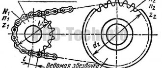
According to the recommendations of GOST 591-69, which regulates sprockets for drive roller and bushing chains, the design is based on the following initial parameters:
- chain pitch t;
- number of z waves;
- engagement circle diameter d1;
The main dimensions that determine the geometric shape of the product are:
- pitch circle diameter D div;
- diameter of the protrusion circle D ext;
- radius of depressions r;
Calculation of the parameters of the chain drive sprocket for a given chain pitch is carried out in the following sequence:
- The axes of the link hinges during engagement with the teeth of the chain drive are located on the pitch circle; the diameter is calculated using the formula:
- Calculation of the circumference of the protrusions:
- Calculation of the radius of the depressions (in mm) r = 0.5025 * d1 + 0.05.
- Calculation of the diameter of the circle of the depressions D depression = D division - 2 * r.
Download GOST 591-69
When constructing a drawing of a sprocket for a chain drive, D ext is calculated with an accuracy of 0.1 millimeters, other parameters are calculated with an accuracy of 0.01 mm.
Parameters and modes of accelerated bench tests of circuits for reliability
B.1 The following groups of circuit tests are established:
A - for chains operating primarily in the transmissions of motorcycles, scooters, in an oil bath or with periodic lubrication;
B – for chains operating primarily in open low-speed gears with periodic lubrication (transmissions of agricultural and similar machines);
B – for chains operating in drives of machines for general industrial use under conditions of periodic lubrication;
G – for chains operating primarily in high-speed gears in an oil bath.
B.2 The conditions for bench tests of circuits for reliability must correspond to those specified in tables B.1, B.2.
B.3 The design load for multi-row chains of types 2PR, 3PR and 4PR, tested according to the modes of tables B.1 and B.2, is determined by multiplying the design load for the corresponding single-row chains by a coefficient equal to:
1.8 – for a double-row chain;
2.5 – for a three-row chain;
3.0 – for a four-row chain.
B.4 The duration of the test according to tables B.1, B.2 is indicated taking into account the running-in period.
For multi-row chains of types 2PR, 3PR and 4PR, the norms of average time to failure and established failure-free operating time are determined by multiplying the average time to failure and established failure-free operating time for the corresponding single-row chains by a coefficient equal to 0.8, respectively; 0.6; 0.5.
B.5 In tables B.1, B.2, the maximum increase in the length of a chain section from its initial value with the number of links according to table 8 is given without taking into account wear during the running-in period.
Table B.1 – Test group A
| Chain size | Basic body parameters | Test modes and results | Maximum increase in the length of the measured segment, mm | ||||||
| Number of links in the circuit | Number of sprocket teeth | Drive sprocket rotation speed, min-1 | Transferable load, daN | Run-in period | Average operating time to failure, no less | Established trouble-free operating time, not less | |||
| leading | slave | h | |||||||
| PR-8-4.6 | 120 | 21 | 21 | 3200 | 25 | 10 | 1000 | 660 | 1,2 |
| PR-9.525-9.1 | 120 | 21 | 21 | 3000 | 60 | 15 | 1100 | 700 | 1,4 |
| PV-9.525-11.5 | 44 | 15 | 31 | 2600 | 36 | 40 | 1100 | 700 | 2,0 |
| PV-9,525-13 | 66 | 24 | 52 | 2600 | 53 | 40 | 1100 | 700 | 2,0 |
| 2PV-9.525-20 | 66 | 24 | 52 | 2600 | 65 | 40 | 1100 | 700 | 3,0 |
| PR-12.7-10-1 | 112 | 19 | 48 | 1200 | 40 | 20 | 950 | 600 | 1,9 |
| PR-12.7-9 | 112 | 19 | 48 | 1200 | 50 | 20 | 950 | 600 | 1,9 |
| PR-12.7-18.2-1 | 110 | 17 | 40 | 1200 | 125 | 60 | 1100 | 700 | 2,5 |
| PR-12.7-18.2 | 110 | 17 | 44 | 1280 | 140 | 60 | 1100 | 700 | 2,5 |
| PR-15.875-23-1 | 100 | 16 | 42 | 1180 | 175 | 60 | 1100 | 700 | 3,1 |
| PR-15.875-23 | 100 | 16 | 42 | 1180 | 220 | 60 | 1100 | 700 | 3,1 |
Table B.2 – Test group B
| Chain size | Base Path Options | Test modes and results | |||||||
| Number of links in the circuit | Number of sprocket teeth | Drive sprocket rotation speed, min-1 | Transferable load, daN | Run-in period | Average time to failure, no less | Established trouble-free operating time, not less | Maximum increase in the length of the measured chain segment, mm | ||
| leading | slave | h | |||||||
| PR-19.05-31.8 | 110 | 19 | 19 | 1200 | 200 | 40 | 1200 | 760 | 1,9 |
| PR-25.4-60 | 110 | 19 | 19 | 800 | 400 | 65 | 900 | 570 | 1,9 |
| PR-31.75-89 | 100 | 17 | 17 | 600 | 605 | 100 | 850 | 540 | 2,4 |
| PR-38.1-127 | 100 | 17 | 17 | 450 | 945 | 150 | 850 | 540 | 2,3 |
| PR-44.45-172.4 | 100 | 17 | 17 | 350 | 1025 | 200 | 800 | 500 | 1,8 |
| PR-50.8-127 | 94 | 17 | 17 | 280 | 1470 | 250 | 750 | 460 | 1,8 |
| PR-63.5-354 | 94 | 17 | 17 | 220 | 2320 | 300 | 650 | 410 | 1,5 |
Keywords
: drive roller and bushing chains, dimensions, breaking load
Design of the hub and disk of chain sprockets
The hub and sprocket disc are most often cast or milled as a single piece. The hub is used to secure the product to the drive or driven shaft of the mechanism. It must provide reliable fixation, eliminating axial and radial runout of the part on the shaft. Therefore, high demands are placed on the quality of the internal surface. Fastening is carried out using:
- spline for high-speed and highly loaded chain drives;
- keys for low-speed chain drives.
The hub diameter must satisfy two requirements:
- ensure structural strength;
- do not make it heavier than necessary.
For cast iron parts, it is usually chosen equal to 1.65 of the shaft diameter; for steel parts, the calculation coefficient is reduced to 1.55.
The length of the hub is determined by the nature of the fixation on the shaft with a key or spline and is usually calculated in the range of 1.2-1.5 of the shaft diameter.
For small sprockets, the width of the disk is chosen equal to the width of the tooth. For large-sized products, especially highly loaded ones, the width is increased to 5%, depending on the radius of curvature of the base of the tooth.
Calculated sizes are rounded to the nearest number in the standard size range.
View catalogs
Sprockets with a pitch of 9.525-12.7-15.875-19.05-25.4 can be purchased ready-made from stock by selecting the required one from the catalog.
Sprockets with pitches from 31.75 mm, 38.1 mm, 44.45 mm, 50.8 mm and more are currently available ONLY to order.
1) The chain sprockets are made of high-quality structural steel 45, which is an essential condition for long-term and trouble-free operation.
2) The sprockets have a heat-treated tooth profile, thanks to special heat treatment using high-frequency “high-frequency currents”, which makes it possible to impart a given hardness, and, accordingly, wear resistance only to the teeth of the chain drive sprocket up to HRC 42 units to the required depth, and, most importantly , only with this method of heat treatment the remaining elements of the sprocket are as follows:
— The rough hole, the one-sided hub of the sprocket (its diameter and length) remain unhardened, with the initial values of the hardness of the material, which allows you to quickly and without additional costs for high-strength tools and time to carry out further machining to the required fit and overall dimensions of the unit itself, where and the sprocket works.
— Also, this processing method allows, with large diameters of the sprocket, to maintain the alignment and flatness of each tooth relative to each other over the entire diameter of the sprocket and to eliminate unacceptable values of possible radial runout due to possible warping during volumetric hardening.
— Low price, thanks to large series production
3) All sprockets supplied are marked on the side surface of the sprocket, indicating the type of chain and number of teeth, thanks to which you can determine the exact nomenclature without much loss of time. For example, the sprocket “08B30”, where: 08 is a simplified digital designation of the chain pitch of 12.7 mm, see the table below
B - indicates the chain series, the chain is manufactured in accordance with DIN 8187-1 30 - the number of sprocket teeth.
Drive sprockets for roller chains
According to the catalog, it is proposed to buy drive sprockets for roller chains in Moscow. There is a wide selection of finished products on sale, and it is also possible to purchase products of non-standard sizes to order. Our company is the official representative of several foreign manufacturers, and the products offered comply with international standards. You can order sprockets for drive chains wholesale and retail at low prices.
Design features and main types
Drive sprockets for roller chains are an integral part of the chain drive. They are metal gears, the teeth engage the rollers of the drive chain and provide energy transmission. Such products are used in various mechanisms: industrial equipment, agricultural machinery, tracked vehicles and much more. The key advantage of chain transmission is its higher load capacity compared to belt transmission, as well as a constant gear ratio. The drive sprockets of roller chains wear out over time: the surface of the teeth wears down, as a result the product ceases to cope with its functions and requires replacement. The roller design of the chain provides the gears with long-term use: sliding friction is replaced by rolling friction, the roller rolls along the tooth of the wheel, which slows down its wear. However, any parts fail over time, so the sprockets must be changed in a timely manner. Our company's catalog contains several types of sprockets:
- Leaders and followers. They differ in their location in the mechanism design and the function they perform.
- Intermediate. They are installed on the driven branch, their task is to prevent the chain from sagging when the distance between the shafts is large.
- Tension. This type of sprocket is designed to tension drive chains, this ensures accurate centering and reduces vibration when the chain moves.
In the catalog you will find a wide selection of finished products that can be used for single-row chains, as well as double-row and multi-row varieties. They are manufactured to ISO 606-94 standard as well as ANSI B29.1M standard.
Selection options
To choose the right sprockets for drive chains, you need to know the name of the mating chain, its pitch and row. In addition, you need to know the required number of wheel teeth or its outer diameter. To ensure that the mechanism operates smoothly, it is recommended to select a sprocket with a large number of teeth. In this case, the drive roller chain will move without jerking, and the transmission ratio will remain constant. If the wheel has an odd number of teeth, it will last longer. Depending on the purpose, the following design options for sprockets for chain drives are distinguished:
- Sprockets with hub. They can be connected to the shaft using a key or bushing, the number of teeth is from 8 to 125.
- Flat gears without a hub. They are used for single-row chains; for double-row chains, a double version can be used. The products have a rough hole for boring to the required diameter in accordance with the dimensions of the shaft.
- Multi-tooth sprockets used for high precision chain transmission.
All products presented in the catalogs are equipped with a stamp on the side surface of the gear. The mark contains information about the suitable type of drive chain and the number of teeth; with its help, you can quickly select products with suitable parameters for a chain of a certain size and purpose.
Chain sprocket materials
Products are subjected to high impact loads, so steel alloys are used for their manufacture:
- with average carbon content and with alloying additives, hardened to a hardness of 45-55 units;
- subjected to cementation to a depth of 1-1.5 mm and subsequent hardening to 55-60 units.
For low-noise chain drives, materials such as textolite, polyamide and polyformaldehyde plastics are used. They absorb shock from roller chain links, reduce noise and vibration, and extend chain life. This occurs by reducing dynamic loads on the links. Such parts are less durable than steel ones, so chain drives with them are limited in terms of transmitted power. An accurate calculation of the transmission of angular position by a gear chain is carried out when designing control system mechanisms, including for aircraft.
For chain drives with low speed (no more than 2 meters per second) and low dynamic loads, cast iron is also used. By heat treatment, the hardness of products is brought to 350-430 HB units. In severe operating conditions, in agricultural machines and road mechanisms, hardened cast irons with a reduced coefficient of friction are used.
To reduce dynamic loads, noise levels and vibration in high-speed chain transmissions, special coatings are also used - both metal surfacing and spraying of a Teflon layer.
8.3.5. Service factor
Operating coefficient K e
The operating conditions of the drive chain are taken into account, affecting the wear rate of the hinges and, in fact, the service life of the chain. It is represented as a product of coefficients:
;
(8.4.)[7, p. 22]
where K d
– dynamic load coefficient, reflecting the influence of the nature of the transmitted load on the wear of the hinges (Table 8.3.5.1.);
K a
– coefficient of influence of chain length or transmission center distance “
a ”
(Table 8.3.5.2.), it is recommended to take
a = (30...50)р c
;
K n
– takes into account the influence of the inclination of the gear to the horizon on the wear of the hinges (Table 8.3.5.2.);
K r
– coefficient of influence of the type of chain tension adjustment (Table 8.3.5.2.); for low-speed gears, the tension is usually unregulated, and excessive sagging of the driven branch is eliminated by one or two chain links;
K T
– reflects the influence of the ambient temperature in which the chain drive operates (Table 8.3.5.2.);
K dir
– takes into account the operating mode of the transmission, or the number of work shifts (Table 8.3.5.2.);
K cm
– coefficient taking into account the influence of the nature of chain lubrication (Table 8.3.5.2.); since the lubrication method is prescribed depending on the chain speed (Table 8.3.5.3.), which is unknown at this stage of the calculation, it can be approximately determined by the dependence:
; (8.5.)[7, p. 22]
where with
– numerical coefficient selected according to the rotation speed of the drive sprocket
n 1
(rpm):
с=1.3…1.5 at n1 ≤ 250 rpm;
с=1.5…1.75 at n1 ≈300…700 rpm;
с=1.8…2.0 at n1 ≥ 750 rpm;
T1
– torque on the drive sprocket shaft, Nm.
Dynamic load factor
Actuator, equipment
The nature of the chain drive
Read also: How to replace the chuck on a Makita drill
Belt conveyors, chain conveyors with minor load fluctuations
Uniform load without shocks and impacts
Conveyors with load fluctuations, compressors, metal cutting equipment, dryers, paper machines
Uniform stroke with individual small shocks;
work with light and medium impacts
Presses, crushers, mining and oil production equipment, rolling mills, other equipment with reversible and shock loads
Medium shocks and extreme pulsating load;
strong impacts or impacts with alternating loads
Coefficients taking into account the operating conditions of the chain drive
Transmission operating conditions
Coefficient of influence of chain length or center distance K a
Center distance a:
Chain tension adjustment coefficient K p
Adjusting the position of the axis of one of the sprockets (moving supports);
adjustment with pull-off stars or pressure rollers;
unregulated center distance.
Chain lubrication coefficient K cm
(recommendations for types of lubrication according to table 7.3.5.3.)
Continuous oil bath or circulation lubrication;
regular drip or intra-joint when working in a clean environment;
internally hinged when working in a dusty environment;
People began using gears back in antiquity. The idea of transmitting torque not through direct contact of two gears, but over a long distance using an endless chain, belongs to the brilliant artist and inventor Leonardo da Vinci. In practice, such drives were implemented at the beginning of the 19th century. In order for the mechanism to work effectively, an accurate calculation of all its elements is necessary, and above all, the sprockets.
LIMIT DEVIATIONS
2.1. Two degrees of precision in the manufacture of sprocket teeth are established:
1st degree of accuracy for sprockets operating in chain drives and devices at speed v
= 3 – 5 m/s.
2nd degree of accuracy for sprockets operating in chain drives and devices at speed v
< 3 m/s, as well as for sprockets that represent an assembly unit.
2.2. The maximum deviations of the main dimensions of the sprockets for degrees of accuracy 1 and 2 must correspond to those indicated in the table. 4.
Table 4
Maximum deviations of the main dimensions of sprockets
| Name of parameters | Sprocket type | Limit deviations for degrees of accuracy, mm | |
| 1 | 2 | ||
| Step difference | 1, 2 | δ tz = 0.01 √ | δ tz = 0.025 √ |
| 3 | |||
| Diameter of the circle of the depressions | 1, 2 | δ Di = -0.032 √ | δ Di = -0.080 √ |
| 3 | |||
| Radial runout of the cavities and axial runout of the ring gear | 1, 2, 3 | δ z = 0.001 | δ z = 0.005 |