Spline connections
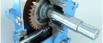
Spline connections are a type of connection between shafts and bushings along mating surfaces of a complex profile with projections (splines) and depressions. They are designed to transmit torque, ensure good centering of the bushing on the shaft, and easy relative movement of parts along the axis. Technologically, these connections are more complex than keyed ones, but due to the large number of splines they allow the transmission of significant torques and provide lower stress concentrations.
Depending on the shape of the tooth profile (spline), straight-sided, involute and triangular spline connections are distinguished. Triangular spline joints with fine splines are usually used for fixed joints. At the interstate level, elements and connections with a straight-sided tooth profile have been standardized (GOST 1139-80 “Straight-sided spline connections. Dimensions and tolerances”) and involute (GOST 6033-80 “Involute spline connections with a profile angle of 30°. Dimensions, tolerances and measured values ").
The most widely used are straight-sided spline joints with an even number of splines, which are used for movable as well as fixed joints. The dimensions and number of teeth of spline connections with a straight-sided profile in accordance with GOST 1139-80 depend on the series (light, heavy). With the same internal diameters, heavy series are distinguished by an increase in the height of the diameter. The heavy series has a larger number of splines compared to the medium one.
In straight-sided and evolveite spline joints, mating (fitting) can be carried out along three surfaces (along the outer cylindrical surface, inner cylindrical surface and along the lateral surfaces of the sleeve cavities and the shaft spline). The difficulties of mating on three surfaces at the same time (unjustifiably high requirements for the accuracy of all elements in size, shape and location) led to certain peculiarities in solving problems:
- for any spline connection, the concepts of centering surface and non-centering surfaces have been introduced;
- in a spline connection, at least two matings are made - along the centering surface and along one of the non-centering surfaces;
- For non-centering mating surfaces, fits with large guaranteed gaps and rough tolerance margins are prescribed, or even a gap of nominal dimensions is provided (without forming a fit).
Matings along the side surfaces of the spline (by size) are carried out in any spline connection (direct, involute, triangular) regardless of the choice of the centering element.
In principle, three methods of centering are possible in any spline connection of the sleeve and shaft (along the outer cylindrical surface, inner cylindrical surface and along the side surfaces of the spline). A schematic representation of centering methods in a spline connection is shown in Fig. 3.112.
The centering diagrams along the outer diameter (Fig. 3.112, a), along the inner diameter (Fig. 3.112, b), and along the lateral sides of the teeth (Fig. 3.110, c) conventionally show gaps along non-centering diameters.
The choice of centering method is determined by operational requirements and technology for producing spline surfaces. To obtain a spline on a shaft, a workpiece in the form of a smooth shaft is usually processed with a special tool (shaping cutter, grinding wheel). The tool has a profile that matches the shape of the cavity, with the full profile being achieved in one or more passes.
A spline hole in serial and mass production is produced by broaching (processing by broaching - a special multi-edged cutting tool that forms the full profile of the spline hole in one pass of the tool). Broaching can be the final operation or after it additional processing of the part is carried out. If, after broaching, the part is hardened, additional processing of the centering element becomes necessary, since heat treatment of a complex part leads to warping of the surface and distortion of the geometric parameters (the part “leads”).
Centering along the outer and inner diameters of the corresponding cylindrical surfaces ( and ) is used to ensure relatively high requirements for the alignment of the sleeve and shaft. Centering along the side surfaces of the teeth is used when there are less stringent requirements for alignment and the need to reduce dynamic loads on the splines. Dynamic shock loads in spline joints arise due to the gaps between the sides of the splines and spline cavities when the product operates in reverse and start-stop modes.
The accuracy of centering the bushing and shaft along the outer and inner diameters ( and ) is almost the same, and the choice of a centering element in such cases is determined by the design requirements and capabilities of the technological equipment.
Centering is used in connections that transmit small torque, when a relatively low hardness of the sleeve is allowed - (40...45). This centering method is used for stationary connections or connections with relatively rare mutual axial movements of parts, in which there is practically no wear on the surfaces. The sleeve (usually after normalization) is finally processed by finishing broaching.
Centering is used for movable spline connections transmitting high torques. In such connections, the sleeve must be sufficiently hard, and since the hardened surface cannot be processed by finishing broaching, the final technological operation of processing the spline hole is grinding along the internal diameter. The tolerance fields for the diameters and sizes of splined shafts and bushings, as well as recommended fits for straight-sided spline joints for various centering methods, are regulated by GOST 1139-80 and are given in table. 3.31-3.33.
Symbols in the drawings
The symbol for a spline connection contains:
- a letter indicating the centering surface;
- number of splines and nominal dimensions, and connections;
- designations of landings placed after the corresponding dimensions.
Tolerance fields for non-centering diameters may not be indicated in the designation.
Examples of symbols for different mates for a straight-sided spline connection with the number of teeth, internal diameter, external diameter, and tooth width are presented below.
Mating designation when centered along the internal diameter, with a fit along the centering diameter and along the width of the tooth:
Designation when centering along the outer diameter, with a fit along the centering diameter and along the width of the tooth:
Designation when centering on the sides of the teeth:
The symbols of individual spline surfaces (internal and external) differ in that instead of fits, the designations of the tolerance fields of the corresponding dimensions are written down. An example of a bushing symbol when centered along the inner diameter:
An example of a shaft symbol when centered along the internal diameter:
The parameters of involute spline connections, including the number of splines (teeth), modulus values, tolerance ranges and fits are determined by GOST 6033-80. The advantages of an involute spline profile over a straight-sided one are the ability to provide slightly better centering on the side surfaces of the teeth, as well as smaller dimensions when transmitting the same moments. The involute spline has increased bending strength because it thickens towards the base.
In involute spline connections, centering along the side surfaces of the teeth is used more often than along the outer diameter. Centering along the inner diameter is also allowed (in this case, the profile should be made with a flat or rounded shape of the bottom of the cavity), but such centering is practically not used.
Since involute splines and cavities have a variable width, special tolerances (with different degrees of accuracy) and original designations (first the degree of accuracy, then the main deviation) have been developed for them, in contrast to straight-sided spline surfaces.
There are two types of tolerances for the thickness of the shaft spline and the width of the sleeve cavities - a size tolerance (- for the thickness of the shaft spline and - for the width of the sleeve cavities) and - a total tolerance, including tolerances for the actual size of the element and tolerances for deviations in the shape and location of the profile elements slot and recesses.
For the width of the bushing cavities, one main deviation and degrees of accuracy of 7, 9 and 11 are normalized. For the thickness of the shaft spline, ten main deviations and degrees of accuracy are set from 7 to 11.
Designations for involute spline connections include nominal diameter, module, fit designation placed after the size or module designation, and standard number.
An example of the designation of an involute spline connection with centering on the side surfaces of the teeth:
(, module, fit on the sides of the slot).
An example of the designation of an involute spline connection with a diameter of , , with centering along and a fit along the centering diameter:
An example of the designation of an involute spline connection with a diameter, when centered along the internal diameter with a fit along the centering diameter:
In addition to dimensional accuracy standards, spline surfaces of parts are subject to additional requirements for the accuracy of shape and location of surfaces, as well as certain requirements for their microgeometry.
When assigning tolerances for the shape and location of spline joint elements, you can be guided by the following recommendations (Fig. 3.113).
For straight spline connections:
- Tolerances for parallelism of the plane of symmetry of the shaft splines (or slots of the splined sleeve) relative to the axis of the centering surface over a length of 100 mm should not exceed 0.03 mm - in high-precision connections (with dimensional tolerances from up to ) and 0.05 mm - in normal-precision connections ( with dimensional tolerances from to ). When centering along the sides of the spline, an additional base is selected - the axis of one of the non-centering surfaces of the spline shaft (usually with a tighter tolerance);
- Tolerances for radial runout of the centering surfaces of the spline shaft (base - the common axis of the seating surfaces of the bearing journals of the shaft) should be assigned according to the seventh degree of accuracy of GOST 24643 with tolerances of the centering surfaces of 6...B grades and according to the eighth degree of accuracy with tolerances of the centering surfaces of 9...10 grades.
For involute spline connections, the limit values of radial runout and tooth direction tolerance should be taken in accordance with GOST 6033.
The surface roughness parameters of the elements of straight-sided and involute spline joints must be consistent with the tightest macrogeometry tolerances. The parameter values should not exceed 1.25 μm for centering surfaces, 2.5 μm for non-centering side surfaces of the splines of movable joints, and for fixed connections - 4.0 μm for non-centering side surfaces of the splines and 10 μm for non-centering cylindrical surfaces of the splines.
Inspection of spline connection elements
To control splined parts, gauges are used. In accordance with the Taylor principle, complex go-through gauges are used, which represent a prototype of the mating part (spline shaft or bushing with a length corresponding to the length of the spline mating) and a set of non-go through gauges for element-by-element control (Fig. 3.114).
Go-through gauges provide comprehensive control of all sizes, shapes and locations of the surfaces of a spline shaft or bushing. The complex gauge must pass under its own weight along the entire length of the controlled surface.
Each of the no-go gauges only checks the actual size of the corresponding element. Using no-go gauges, each element of the part is checked in a number of sections, and passage in any of the controlled sections gives grounds to recognize the part as defective.
The tolerances of gauges for testing splined parts are regulated by GOST 7951-80 (for straight-sided ones) and GOST 24969-81 (for involute splined parts).
This lecture is taken from the lectures page on standardization of accuracy:
Standardization of accuracy: course of lectures
Perhaps these pages will help you:
| Pin connections: designations and purpose |
| Keyed connections: designations and purpose |
| Interchangeability, methods for monitoring gears and gears |
| Mathematical processing of measurement results |
Selection of equipment and tools
Cutting is performed on machines:
The parts are then polished on grinding machines.
In small-scale and individual production, spline cutting is very often carried out on spline milling or gear hobbing equipment using a hob cutter and the rolling method. The use of such a tool is effective for both straight-sided and involute splines.
A horizontal milling machine for cutting splines is used in conjunction with a shaped disc cutter. For simultaneous cutting of several grooves, a dividing head is used. It is worth noting that this method is used extremely rarely for the manufacture of splines due to inaccuracies in pitch and width. It would be advisable to rough-process the part on a horizontal milling machine with a disk cutter, leaving allowance for finishing and grinding. Finishing of the grooves is carried out with special end mills, and for a triangular spline connection, triangular cutters are used.
The running-in method using a cutter is used. For the high quality of the resulting surfaces, gear shaping equipment is used in mass production.
In addition to slotting machines, planing and broaching machines have become widespread in the mass and large-scale production of spline joints. Such equipment is several times more efficient and productive than milling machines. Planing cutting is carried out using a set of cutters, the number and dimensions of which depend on the number of teeth, the width and depth of the joint grooves. When broaching, a tool called a broach is used. This tool has several cutting teeth of different heights, which, when moving forward, cut off part of the metal from the workpiece.
For the manufacture of involute joints, cold rolling is used using special roller heads. This tool produces products with a large number of teeth. The cold rolling method is 10 times more efficient than milling.
After cutting the teeth and heat treatment, all products are ground. This allows you to achieve the required roughness and avoid snagging of mating parts during operation. For grinding use the following tool:
In some cases, a mandrel is used to grind internal surfaces.
Application
The need to use gear connections arises when it is necessary to transmit large torque and high demands are placed on the alignment of the driving and driven parts and the accuracy of movement. Splines allow the bushing to move along the axis, changing the gear ratio without stopping the mechanism. Due to this, they are used in gearboxes of cars, machine tools, and loading units.
The purpose of the spline, like the key, is to transmit torque at a given angular velocity.
The load distribution relative to the axis of rotation is uniform, according to the number of teeth, radial runout is eliminated. This is used in precision instruments where precision is required.
Rotation using triangular teeth is found in household appliances and power tools:
In all areas of mechanical engineering, machine tool construction, machines and other vehicles, a compact and powerful rotation transmission unit is used.
Advantages and disadvantages
When designing mechanisms that transmit rotation with high loads, they most often choose a splined connection. It has enormous advantages in certain cases and can replace several keyed joints. There are also disadvantages. It is necessary to weigh all the arguments for and against when choosing a connection method.
Compared to keys, the advantages of spline connections include:
The splines are manufactured in accordance with GOST and Standards, have strictly standardized dimensions and the parts for the connection are easy to select. Simplified assembly of components and fitting of parts.
The disadvantages of spline connections include:
When overloaded, the key is simply cut off, preventing the transfer of increased load to the working mechanism and preventing its breakage. The part is simple and cheap, easy to change.
In spline joints, in an emergency, a tooth or the entire machine may break. Replacing parts is difficult and expensive.