Our company has been producing shafts, axles, bushings, pulleys and other products obtained by turning in St. Petersburg for more than a quarter of a century. You can also perform a wide range of metalworking work with us. We manufacture custom parts according to the Customer's drawings, sketches and samples.
Just call us or send us a drawing by email!
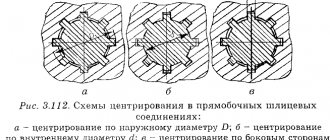
Let's consider the concept of fit using the example of manufacturing axles (shafts) and bushings (their internal holes) according to the Customer's drawings.
How to connect mechanism shafts?
To transmit axial rotation, shafts are used, on which various gears and sprockets can be mounted. The connection is carried out using various methods, for example, couplings are used to connect shafts. Their features include the following points:
- It is possible to dismantle.
- The collection and production of the final product is greatly simplified.
- Many types of products allow you to compensate for various types of displacements that may occur during operation of the device.
- The device can withstand significant load.
Today, parts are connected to each other using welding technology extremely rarely. This is due to the fact that vibration and other impacts can cause cracks and other defects.
Incorrect fixation may result in device failure. The product is selected depending on the operating conditions. For example, shafts can move in a variety of directions.
Typical damage to working surfaces
Fatigue spalling
– the most common damage to the tooth surface. Small depressions appear on the working surfaces, which turn into sinks. The spalling is of a fatigue nature and is caused by contact stresses. Chipping leads to increased contact pressure and disruption of the transmission. In open gears, the surface layers wear away before fatigue cracks appear in them.
To prevent chipping, it is necessary to increase the hardness of the material by heat treatment, or increase the degree of transmission accuracy, and correctly assign dimensions based on contact stress fatigue.
Abrasive wear
is the main cause of gear failure due to poor lubrication. These are open transmissions, as well as closed ones located in a clogged environment. For worn gears:
- gaps in engagement increase, noise, vibration, and dynamic overloads increase;
- the shape of the tooth is distorted;
- cross-sectional dimensions and tooth strength decrease.
The main measures to prevent wear are increasing the hardness of the tooth surface, protecting against contamination, and using special oils. When calculating contact endurance, abrasive wear is taken into account by underestimating the permissible contact stresses.
Jamming
occurs in highly loaded and high-speed transmissions. At the point of contact of the teeth, an increased temperature occurs, leading to molecular adhesion of the metal with subsequent separation. The torn particles then scratch the rubbing surfaces.
Typically, seizures occur due to the squeezing out of the oil film between the teeth. Preventive measures - correct choice of oil type and cooling.
Fractured tooth
– failure is associated with bending stresses that have a pulsating nature.
A broken tooth can lead to very serious consequences, including the destruction of shafts and bearings. To prevent fracture, the tooth is calculated using bending stresses. This calculation for closed gears is performed as a test after calculating contact stresses. For open gears, where there is a high probability of accidental overloads, this calculation is performed as a design calculation. Fatigue chipping, abrasive wear and galling are caused by the surface strength
, and fracture is caused by
the volumetric strength of the teeth
.
Since surface damage is the main type of failure for closed gears, the calculation for contact endurance is performed as a design one; bending calculation - as a test. For open passes it’s the other way around.
Homemade coupling
To significantly reduce costs, the possibility of using a homemade design is being considered. Among the features we highlight the following points:
- To create a homemade design, you need a sprocket that can be removed from the crankshaft of an internal combustion engine.
- The transmission of rotation is carried out using a chain. Due to the use of steel in the manufacture of this product, strength increases significantly.
- The connection is made through two coupling halves. In this case, the star should be sawn in half. A cut-off part of the sprocket will be welded onto each coupling half.
- The coupling half is fastened using bolts. However, this connection method is not recommended if the load applied is significant. Fixation of detachable elements is ensured by a key when transmitting high force.
The above information indicates that such a product can be made using available materials. In this case, the resulting device is installed to transmit high torque.
Basic requirements for the accuracy of gear assembly
When installing and assembling gears, the following requirements are imposed to check the correctness of the work:
- checking the specified center-to-center distance, parallelism of the shaft axes and absence of distortions (Figure 4.35);
Figure 4.35 – Checking the parallelism of the shafts
- checking the pitch circle;
- radial and axial runout of the gear wheel should not exceed the maximum values;
- side clearance measurement;
- checking tooth thickness;
- checking wheel alignment;
- final check of paint engagement (Figure 4.36, Figure 4.37).
Figure 4.36 – Check when adjusting the engagement of the teeth of a bevel gear using paint: a) correctly adjusted engagement (a clear imprint of paint, shifted to the thin part of the tooth); b) reduced radial clearance; c) increased radial clearance; d) axial displacement of the wheels (it is necessary to move the drive wheel)
Figure 4.37 – Checking the correct installation of the worm wheel relative to the worm using a paint imprint on the teeth (H is the entry point of the worm turn into the teeth of the worm wheel): a) correct engagement (the contact spot is located symmetrically and occupies 70...75% of the tooth surface); b), c) the worm wheel is shifted away from the axis (the arrow shows the direction of the shift to eliminate the defect); d) the worm wheel is skewed; e) increased center-to-center distance; e) reduced center-to-center distance
In cylindrical gears, the non-parallelism and misalignment of the shafts should not exceed (for every 1000 mm of length) the values indicated in Table 4.6.
Table 4.6 - Allowable values of skew and non-parallelism
| Types of gears | Limit value, mm | |
| non-parallelism | skew | |
| In gearboxes | 0,3 | 0,25 |
| In open gears with the module: | ||
| up to 6 mm | 1,0 | 0,8 |
| from 6 to 14 mm | 0,8 | |
| from 14 to 20 mm | 0,6 | 0,5 |
The non-parallelism of the shafts can be established with a caliper, using a stretched string and a surface planer, with a gauge, and the misalignment of the shafts can be determined by a level with a division value of 0.1 mm per 1000 mm of length.
In worm gearboxes 2Ch-40, 2Ch-63, 2Ch-80, to save cutters and ease the assembly of gearboxes, the initial contact patch is located in the middle part (Figure 4.38a). This is the main reason for the occurrence of scoring on the surface of the teeth, intense heat generation, and a decrease in the efficiency of the gearbox. The durability of such transmissions is significantly reduced.
(A) | (b) |
Figure 4.38 – Options for the location of the initial contact patch on the side surface of the worm wheel teeth (for the right direction of the worm turns), where 1 is the direction of rotation of the worm; 2 – middle plane of the worm wheel; 3 – the end of the teeth on the side where the worm turns disengage from the wheel tooth: | |
a) initial spot in typical designs of gearboxes 2Ch-40, 2Ch-63, 2Ch-80; | b) optimal initial contact patch used in modernized gearboxes 2Ch-40M, 2Ch-63M, 2Ch-80M |
The 2Ch-40M, 2Ch-63M, 2Ch-80M gearboxes use worm gears with an optimal location of the initial contact patch at the end of the teeth at the exit of the worm turn from engagement (Figure 4.38b) - a prerequisite for high performance, reliable and long-term operation of modernized worm gearboxes.
| < 4.5. Examples of rolling bearing disassembly diagrams | Content | 4.7. Shaft alignment > |
0 0 votes
Article rating
Classification of couplings
There are many different similar products that are used to transmit rotation. The classification by purpose is as follows:
- Permanent or connecting.
- Coupled and steerable.
Drive models are installed in a wide variety of designs. Neither are required for direct force transmission.
Shaft connecting products are used for constant transmission of rotation. They are divided into several main groups:
- Tough.
- Deaf.
- Connecting.
- Movable or flexible.
The simplest design option can be called blind couplings. In the manufacture of bushings and other elements, a wide variety of materials can be used, most of which are characterized by a high degree of protection from environmental influences.
Cone adapter couplings have become quite widespread, as they are easy to manufacture and can last for a long period. Splined versions can also be installed, which can transmit large forces during operation.
The classification of flexible design options is also carried out according to a large number of different characteristics. The following are widely used:
- Expansion. They are characterized by the fact that they can compensate for the axial displacement of parts relative to each other.
- Cross. Such mechanisms are installed in cases where there is a possibility of radial displacement.
- Membrane and drive, which are designed for radial and axial displacement. The leashes have a special element that ensures the position of both elements is fixed.
The selection of the most suitable connecting element is carried out according to the diametrical dimensions. The coupling halves compensate for the displacement of the axis, however, to increase the efficiency, oil is added. In most cases, steel is used in manufacturing, which is characterized by increased wear resistance. If it is necessary to protect the mechanism from the effects of electricity, special materials with certain properties are used.
Do not forget that cross products are characterized by a significant drawback - an increase in backlash due to severe wear of the protrusions.
In some cases, a leash version is used, which is also characterized by certain advantages and disadvantages.
What fits can a shaft be made with?
However, the standards try to limit all possible combinations of fits, used deviations and qualities. When producing axles , shafts, bushings and other parts, you should try to use only the recommended fits. And among them, give preference to the “preferred” ones, which in tables are usually highlighted in bold or with a bold frame:
The assigned degree of surface roughness of the mating parts depends on the choice of fit.
Rigid shaft connection
A fairly large number of different methods of connecting shafts are used, all of them are characterized by certain qualities. The rigid connection method is used when the connection is made taking into account the absence of the likelihood of the nodes moving relative to each other at the time of operation. The classic connection method is characterized by the following features:
- In most cases, the connection is made using flanges, which are part of various mechanisms. Installation of rigid couplings is also carried out; their installation is carried out using the pressing method.
- The single-support version of the shaft has become quite widespread. In this case, the connection itself is used as a second support.
- Bolts can also be used for fixation. At the same time, they must fit tightly into the hole, otherwise serious problems may arise.
- In this case, a gear or transversely folded coupling is often used.
The transversely folded version is used for connecting various parts that are installed in electrical machines and other various units. This design consists of the following elements:
- Two coupling halves. They are mounted on the ends of shafts, which are connected into one system.
- Both parts of the structure under consideration have centering protrusions and a special recess; the connection is ensured by strong bolts.
- Safety couplings cannot be turned due to a special key hole.
- Axial displacement is eliminated due to locking screws that are screwed in at the ends.
A more complex version can be called a gear coupling, which also consists of two separate parts. The outer surface consists of teeth that mesh to ensure a reliable connection. Axial displacement is eliminated through the use of bolts.
Landings
Nominal size Dn=dn 100,000 100,000 100,000 Limit sizes. hole DmaxDmin
100,035100,000
100,035100,000
100,035100,000
Limit shaft dimensions dmaxdmin
99,92899,874
100,025100,003
100,073100,051
Hole tolerance TD 0.035 0.035 0.035 Toleranceshaft
Td 0.054 0.035 0.022 Limit clearances SmaxSmin
0,1070,072
0,032——
—-—-
Ultimate tension NmaxNmin
—-—-
0,025—-
0,0730,016
Average clearances Sav 0.0895 0.0035 —- Average interference Nav —- —- 0.0445 Fit tolerance with clearance TPS 0.035 —- —- Transitional TPP —- 0.057 —- With interference TPN —- —- 0.016Semi-rigid shaft connection
The semi-rigid type of connection is characterized by certain features. An example is the case of connecting a turbogenerator shaft to a steam turbine. In most cases, a semi-rigid gear-spring coupling is placed on the motor shaft.
The considered version of the connecting element is characterized by the following features:
- The design consists of two coupling halves, which are fixed on both parts. The device is installed in a similar way.
- Fixation of one element relative to another is carried out due to an elastic wave-shaped tape spring, which is often called a compensator.
To ensure the required level of protection, a casing is used, which is made from a variety of environmentally resistant materials. Minor changes in the position of the two elements being connected are compensated by a special element.
Main characteristics of interfaces in the 100JT7mm shaft system
Characteristics | Legend | |||
| Nominal size | Dn=dn | 100,000 | 100,000 | 100,000 |
| Limit sizes hole | Dmax Dmin | 100,126 100,072 | 100,016 99,962 | 99,876 99,822 |
| Limit shaft dimensions | dmax dmin | 100,000 99,965 | 100,000 99,965 | 100,000 99,965 |
| Hole tolerance | T.D. | 0,054 | 0,054 | 0,054 |
| Tolerance shaft | Td | 0,035 | 0,035 | 0,035 |
| Limit clearances | Smax Smin | 0,161 0,072 | 0,051 —- | —- —- |
| Limit interference | Nmax Nmin | —- —- | 0,038 —- | 0,178 0,089 |
| Average clearances | Sav | 0,1165 | 0,0075 | —- |
| Average interference | Nav | —- | —- | 0,1335 |
| Clearance fit tolerance | TPS | 0,089 | —- | —- |
| Transitional | Chamber of Commerce and Industry | —- | 0,089 | —- |
| With interference | TPN | —- | —- | 0,089 |
Elastic shaft connection
At the time of operation of the device, there is a possibility of displacement of two elements relative to each other. This problem can be solved through the use of special elements. Elastic devices can be installed in a wide variety of cases, they are characterized by the following features:
- Installation is possible in case of lateral or angular displacement of the shafts at the interface.
- Bush-pin parts have become quite widespread.
The classic device is represented by two coupling halves, which are connected using special bolt pins.
Special leather washers and cuffs are placed on the surface, which are secured using rubber cuffs.
What is a hinge
A hinge is a kinematic pair, one element of which performs a rotational movement, turning relative to the second element. The simplest and most commonly used hinge is the door hinge. A distinctive feature of the hinge joint, which is used in mechanics, is the ability of the structural parts united by it to perform angular movement. In hinges there is no transfer of bending moment between parts of the structure.
In diagrams and technical drawings, a hinge joint is depicted as a circle of small diameter. This circle can combine two or more structural elements, sometimes adjacent to only one.
If the image of a hinge is superimposed on the image of a beam, it means that the beam has a composite structure assembled on hinges. If the hinge is only adjacent to it in the diagram, then such a beam is solid, a hinge is connected to it.
Installation of a friction clutch on a high-speed shaft
If necessary, you can install the friction clutch yourself with a small set of tools. To obtain a high-quality result, you need to follow common recommendations:
- Before starting work, you should make sure that the structure does not have significant defects. Even minor defects cause a decrease in the strength of the connection.
- Elastic couplings have become quite widespread. Their peculiarity lies in the presence of a special element, due to which displacements are compensated. At the time of installation, you need to be careful, since too much force can cause damage to the active element. This should also be taken into account when installing safety couplings.
- In most cases, fixation is carried out by pressing the mechanism. You can eliminate the possibility of the device turning by using a key.
At the time of installation, it is not recommended to use a makeshift fixation method, as this may cause damage to the structure. An example is a change in shape and the appearance of dents, cracks, a decrease in strength and many other points.
Hello student
Shaft-bushing connections include connections with coaxial male and female surfaces designed to transmit torque. The term “shaft” should apply to both shafts and axles, and other parts with a covered surface. The bushings can be gears mounted on a shaft, coupling halves, pulleys, sprockets.
Keyed connections
Keyed connections are used to connect parts to shafts using keys that are installed in the grooves of the part and the shaft and transmit torque.
The connections are widely used due to their simplicity of design and low cost. Their disadvantages are the weakening of the shaft by the keyway and a decrease in the fatigue strength of the shaft due to stress concentration. It is not recommended to use keys on hollow shafts.
The most commonly used key connections are using prismatic and segment keys.
For parallel keys in certain ranges of shaft diameters, the dimensions of the key section (width b, height h, chamfer c or radius of curvature r) and the dimensions of the grooves (depth of the shaft groove t and sleeve t1 and radius of curvature r) are standardized. The length of the key is selected from the standard.
For segment keys in certain intervals of shaft diameters, the dimensions of the key (width b, height h, diameter dIII, chamfer c) and the dimensions of the grooves (depth of the shaft groove t and bushing and radius of curvature r) are standardized.
Through grooves for the key in the bushing are made by pulling, and blind grooves are made by chiselling. The grooves on the shaft are milled: for a parallel key - with a finger cutter, and for a segment key - with a disk cutter. To avoid fitting the ends of the parallel key, the length of the groove l' is made greater than the length of the key l. It is not recommended to extend the grooves into the shaft steps, since cutting them into the step increases stress concentration.
The connection with a segment key is more technologically advanced than with a prismatic key, but the depth of the groove on the shaft is greater, which greatly weakens the shaft. The short length of the key limits the load-bearing capacity, so segment keys are used to transmit small torques.
Rice. 1
Rice. 2
The key is made with a deviation of width h9 and is placed in the shaft groove with interference, and in the sleeve groove with clearance. Accordingly, fits in the shaft system are recommended P9/h9 and Js9/h9 for a parallel key, N9/h9 and Js9/h9 for a segmental key. Parallel keys can be used as guides in movable key joints. In this case, it is recommended to fit into the groove of the H9/h9 bushing.
The bushing is installed on the shaft using a transition fit H7/k6 or an interference fit under cyclic loading, and is fixed in the axial direction by a shaft collar, nut, end stop, set screw or other means.
Using a key, the bushing is fixed to the shaft in the circumferential direction. Under the influence of torque, crushing, shearing and bending stresses arise in the key. But in standard-section keys, the shear and bending stresses are small, so the strength of the keyed connection is checked only by bearing stresses:
where FCM is the resulting force acting on the side face of the key, FCM * T/(0, 5d); Acm is the crushing area of the side face, Acm = lph/2 - for a parallel key, Acm = l(h - t) - for a segmental key; T is the design torque; [asm] - permissible bearing stress.
For fixed keyed connections, the permissible bearing stress for different loads is recommended as follows: for static - [asm = 0.8at, for pulsating - [atcm] = 0.55at, for alternating load - [asm] = 0.4at. The at value is taken for the least durable material of the connection parts (key, shaft or bushing). In LA connections, keys made of clean-drawn steel 45 or steel 30KhGSA are used.
The length of the coupling between the bushing and the shaft L is usually taken equal to (1... 1, 2)d. The use of axial tightening of the connection based on the ends of the bushing makes it possible to reduce it to a value of less than 0.8d.
If the strength of the connection is insufficient, it can be increased by using a key of a larger standard section (if the shaft strength is sufficient) or by increasing the length of the parallel key. Installing two keys along the centering circle is undesirable, since it does not increase the strength of the connection due to the uneven distribution of the load between the keys, but reduces the strength of the shaft.
In addition to connections with parallel and segment keys, connections with cylindrical keys are used, which use standard cylindrical pins with dIII < 0, 2d. The pin is inserted into the hole using an interference fit. Such a connection can only be made if the tool is conveniently accessible for jointly drilling and reaming holes at the ends of the bushing and shaft. Joint processing of the iodine key hole on the shaft and in the bushing allows you to obtain a lot
Rice. 3
keyed connection (up to four keys) with uniform load distribution between the keys. In combination with low weakening of the shaft section and low stress concentration, this results in a high load-bearing capacity of the connection. However, the connection turns out to be permanent. The strength of such a connection is checked using the formula where the crushing area of one key is Acm = lpdIII/2.
For axial fixation of the bushing on the shaft in the case of a connection with cylindrical keys, several screws are usually used, evenly spaced along the centering circle. Threaded holes for screws, as well as holes for keys, are made in the bushing and shaft assembly.
Literature used: Machine parts and design fundamentals: textbook. for universities / G. I. Roshchin, E. A. Samoilov, N. A. Alekseeva and others; edited by G. I. Roshchin and E. A. Samoilova. - M.: Bustard, 2006. - 415, [1] p.: ill. - (Higher education).
Download abstract: You do not have access to download files from our server. HOW TO DOWNLOAD HERE
Archive password: privetstudent.com
Installation of friction and ball safety clutches on a low-speed shaft
Safety devices eliminate the possibility of damage to main elements in the event of overload. In this case, the installation process is practically no different:
- Fixation is carried out using a dowel. This method is characterized by very high reliability.
- The coupling halves are fitted under tension. This eliminates the possibility of backlash and other problems.
- When fitting, do not apply much force, as a serious defect may occur.
There are special tools on sale that greatly simplify installation work.
Where is the swivel joint applicable?
It is possible to use a hinged connection in practice in accordance with its degree of freedom. A complex hinge can have up to six degrees of freedom in the assembly. Three degrees are for translation, and three are for rotation. The more degrees of freedom, the more interesting the joint is for the modeling process.
A simple cylindrical hinge is common in household and industrial engineering: all types of door connections, plumbing elements (rotary faucets), tools such as pliers, scissors, any where flat parts are displaced, etc.
The spherical (ball) joint is used in the automotive industry in the chassis, in remote controls, in mechanical engineering and robotics.
Cardan (Hooke's joint) in the transmission of rotational motion from the engine to the rear-wheel drive of a car, from the power take-off shaft to attachments in special equipment, wherever the transmission occurs between shafts located at an angle.
Movable CV joints are installed in front-wheel drive vehicles.
Installation of friction clutches on the low-speed shaft of the output gearbox
Often the product is installed on a gearbox to connect it to an electric motor. This can be attributed to the fact that the gearbox may jam, which leads to overheating of the engine. A friction clutch eliminates the possibility of such a problem. Among the installation features we note:
- Do not apply impact loads as they may damage the product itself.
- To simplify the entry of the cage, lubricant can be used.
- Violation of installation rules may cause damage to the main part.
Self-installation should be carried out exclusively taking into account the recommendations, since even a minor defect causes a reduction in service life.
There are simply a huge number of different parts on sale, due to which there are no significant problems when choosing. The main criteria include the type of material used in manufacturing, as well as the diametrical size. When choosing, attention is paid to how the displacement of the connected elements can occur.
Gear Assembly
For gears and gears, degrees of accuracy are provided: 5, 6, 7, 8, 9, 10, 11 (the designation is given in descending order of accuracy). Standards are presented for the kinematic accuracy of the wheel, smooth operation and tooth contact. Kinematic accuracy is the total error of the gear rotation angle per revolution. The smooth operation of the wheel is determined by turning the assembled gear with a torque wrench. The tooth contact standards determine the size of the contact patch of mating teeth (Table 4.4). Regardless of the degree of accuracy, lateral standards have been established ( aN
) and radial (
aP
) clearances:
aH = (0.02…0.10) × m
;
aP = (0.15…0.30) × m
(Table 4.5).
Table 4.4 – Standards of tooth contact in cylindrical gears, %, not less
| Degree of accuracy | By height | By lenght |
| 3 | 65 | 95 |
| 4 | 60 | 90 |
| 5 | 55 | 80 |
| 6 | 50 | 70 |
| 7 | 45 | 60 |
| 8 | 40 | 50 |
| 9 | 30 | 40 |
| 10 | 25 | 30 |
| 11 | 20 | 25 |
Table 4.5 – The amount of lateral clearance in the engagement of cylindrical gears, mm
| Center distance, mm | Accuracy class | |
| 3 | 4 | |
| up to 100 | 0,10…0,35 | 0,15…0,45 |
| 100…200 | 0,12…0,45 | 0,17…0,60 |
| 200…400 | 0,16…0,60 | 0,21…0,80 |
| 400…800 | 0,24…0,85 | 0,29…1,10 |
| 800…1200 | 0,32…1,20 | 0,37…1,60 |
| 1200…1600 | 0,44…1,60 | 0,45…2,10 |
| 1600…2000 | – | 0,53…2,60 |
The side clearance in large gears of a large module is checked by rolling lead wires between the teeth, installed along the length of the tooth. The diameter of the wires is 1.4...1.5 times the side gap. Each wire is lubricated with technical petroleum jelly and placed on the tooth in the form of a U-shaped bracket. The thickness of the flattened parts of the wires on both sides of the tooth is measured with a micrometer, which in total gives the lateral clearance. At the same time, the non-parallelism and misalignment of the axes are determined.
When checking the norms of tooth contact, the teeth of the smaller wheel are coated with a thin layer of paint and the gear pair is rotated, after which the traces of contact on the teeth of the large wheel are examined. The main reason for improper fit is non-parallelism and misalignment of the axes of the holes in the housing or errors in the gear-shaft assembly. Heating the female part above the tempering temperature is prohibited.
Lubricants used for hinge joints
- Lithium based. Reliable greases with high preservation characteristics. Reduces loads on node connections up to ten times. Neutralizes dust and is compatible with almost all polymer materials for anthers. Disadvantage: they have low anti-corrosion protection and destroy some plastics.
- Based on molybdenum disulfide. Long-lasting lubricants up to one hundred thousand mileage. Excellent lubricating and anti-corrosion characteristics. Does not destroy plastics. Disadvantage: if moisture gets in, the lubricant loses its properties.
- Barium based. Good lubricants with the advantages of lithium and molybdenum disulfide. They are also not afraid of moisture. The disadvantage is destruction at low temperatures and high price.