To reliably hold gases under pressure up to 180 atm, cylinders with thick walls up to 6 mm are used. To dose the gas supply, cylinder valves are used, to which reducers are connected. In order not to produce many different reducers according to the connection method, cylinder valves are produced in certain sizes and standards, and are designed for installation on gas cylinders with a volume of 10 to 40 liters. We will consider further what their structure and types are, as well as the rules of operation. This will help you choose the right equipment and use it correctly.
Checking tightness and completing work
When checking the tightness of the valve connection, you will need to pump gas under pressure into the gas cylinder.
This can be done in two ways:
- Pump gas using compressor equipment or a car pump.
- Connect two cylinders with a hose, the first of which is empty (tested), and the second is filled with gas.
First, under the control of a pressure gauge, you need to fill the test cylinder with gas with a pressure of 1.5-2 atmospheres. After this, soap foam is applied to the connection and the tap is opened slightly.
If soap bubbles are not inflated anywhere, then the connection is sealed. But if even slight swelling of foam appears, you will have to re-tighten the valve.
When immersing the valve in water, it is advisable to close the side fitting with a plug so that water and suspended particles contained in it do not get into the locking mechanism
If the cylinder is small, then you can immerse its valve in a small bowl of water and see for bubbles.
After replacing the shut-off valves, the corresponding mark must be placed in the gas cylinder passport.
It should be remembered that the methods described above for replacing a used valve are applicable only to metal tanks. If you have a composite gas storage cylinder, you cannot act this way because of the possibility of damaging the flask and breaking its seal.
Marking
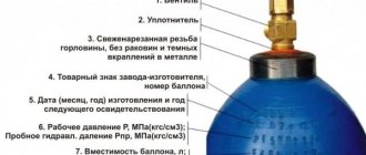
For marking, only special uniform stickers and color designations according to GOST are used: the oxygen cylinder is painted blue, and on top there is a stencil with the name of the gas made with black paint. The steel thickness is in the range of 6-8 mm, the product has no connecting joints, which increases operational reliability.
The factory marking is applied to the unpainted area under the valve; it must contain:
- cylinder number;
- group and nominal, also actual capacity in liters;
- weight in kilograms;
- testing and operating pressure;
- date of inspection;
- period of repeated hydraulic testing;
- manufacturer's and technical control mark.
It is prohibited to use containers without the above information.
Screwing in new shut-off valves
Before tightening the valve, all connected parts must be degreased to prevent clogging of the locking mechanism. To do this, you can use a cloth with regular detergent or moistened with white alcohol. After this, rinse the surfaces with plain water and allow them to dry.
A new valve is never screwed to a cylinder with bare threads. It is imperative to use a sealant: special thread compound or fluoroplastic fum tape. They are applied to the lower fitting and only after that the valve is tightened.
No additional gaskets are expected to be used between the valve and the cylinder body; a seal and appropriate clamping force will suffice
The thickness of the gas fum tape is greater than sanitary tape and is 0.1 - 0.25 mm, and its reel should be yellow. The tape is wound with tension in 3-4 layers. It is better to twist it once again when it breaks than to make the seal loose.
It is advisable to tighten the valve with a torque wrench. Steel shut-off valves are screwed with a maximum force of 480 Nm, and brass valves - 250 Nm. After clamping the valve, you can proceed to subsequent steps to test the tightness of the resulting connection.
The procedure for carrying out regular tests of cylinders
Regular tests of cylinders are carried out in accordance with RD 03112194-1094-03 and RD 03112194-1095-03. Employees who perform such work must undergo appropriate training and have the appropriate knowledge and skills.
The next tests are carried out in the following sequence:
- Acceptance of containers. At this stage of the inspection, the completeness of the cylinder is checked and the external surface is inspected. At the same time, the date of the last inspection and pressure testing is checked. If necessary, the inner surface of the container must be cleaned.
- Inspection of the inside of the container is carried out using specialized equipment.
- The fittings are dismantled and inspected. In addition, during the inspection process, technological parts can be installed, without which it is impossible to conduct hydraulic tests.
After hydraulic testing (pressure testing), it is necessary to dry the vessel from traces of the reagent. Return the dismantled fittings to their place.
The cylinder must be prepared for priming and painting. To do this, it is sandblasted. After applying a coating of the appropriate color and drying it on the surface of the cylinder, it is necessary to carry out marking in accordance with regulatory documentation. The completion of the survey work is documented by a corresponding act. The total time to complete all of the above work is 3 – 5 hours. This time includes both preparatory and main operations.
How to refill a gas cylinder?
Such devices are refueled at special points, which can be located autonomously and be part of a gas station. In the latter conditions, it is possible to refuel with gas engine fuel.
The most important nuance in this process is the fact that you need to refuel not by volume, but by weight. If you are guided by safety precautions, gas containers should be filled to a maximum of 85 percent of the total volume to avoid excessive pressure.
In order to follow safety precautions and its standards, such a device with any volume is marked with a number with a maximum permissible weight, thereby corresponding to the permissible 85 percent. The containers are placed on the scales, including fuel injection. The process stops after reaching the required mass.
But even when filling relative to the mass, overflows are not excluded, which is especially important for small-volume containers - 5 or 12. They should be filled with 2 and 6 kilograms, respectively. A high filling speed sometimes makes it impossible to see that the maximum limit has been reached. If this happens to you, be sure to ask for the excess gas to be drained. In the future, it is better to choose another place for refueling.
In general, the basic criterion for choosing a tanker is whether it has licensing documents for the use of fire and explosive objects. If the documents are present, then we can conclude that you are being served by qualified specialists who undergo special certification annually.
In other cases, you take responsibility for the operation of the refilled container. And you risk not only your money, but also the safety of your home and life. In addition, an unlicensed gas station is a violation of the law and may entail not only administrative, but also criminal liability under the article on illegal business activity.
The information provided in the review does not claim to be accurate encyclopedic data and is largely dictated by our experience. But we are confident that it can help you save a lot of time and money.
How to calculate the optimal amount of gas?
The amount of fuel required for travel is calculated individually in each case. When calculating fuel consumption, the characteristics of the trip are taken into account. When planning a trip in a harsh climate, special attention should be paid to such an element as a windbreak. Without this additional module, the burner efficiency is significantly reduced and heat loss increases.
Gas calculation for one person:
- Economical use – 50 grams.
- Normal conditions are 80 grams.
- Comfortable conditions -100 grams.
When planning a mountain climb, the required volume of gas for one person per day is approximately 160-200 grams.
Portable gas cylinders gave a powerful impetus to the development of the production of travel heating pads. Today it is one of the most popular types of fuel, which can significantly increase travel comfort.
Types of gas valves
Before examining shut-off valves in detail, it is necessary to clarify that they are just a part of a container for transporting and storing various gases under pressure. Cylinders are manufactured from carbon or alloy steel in accordance with GOST 949-72. They differ from each other in color and volume, but the device is the same. Thus, a gas cylinder consists of a valve, a seal, a thread and a seamless tank with the passport data assigned by the manufacturer stamped on it.
Valves are divided into several types, depending on what the cylinders are filled with: liquefied gas, oxygen or propane-butane. At the same time, there are practically no distinctive design features; only the valve markings differ according to GOST standards:
Operating rules
Welding is a particularly dangerous type of production activity, therefore there are rules for the transportation and storage of oxygen:
- Strict marking and painting in the appropriate color.
- The initial pressure inside the container is 150 atm, maximum use is allowed up to 1 atm, the valve is closed, and the cylinder is sent for refueling.
- Full consumption is prohibited, since the oxygen station must determine its type.
- Transportation only on racks with shock absorbers, where each container is securely fastened.
- In production and construction sites, containers are transported only on trolleys.
- When used, the cylinder is located no closer than 5 m from the welding site.
- It is forbidden to keep containers in direct sunlight for a long time.
- It is necessary to close the cylinder from exposure to precipitation.
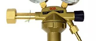
- The reducer automatically regulates the gas supply; it must be kept clean.
Periodically, all similar containers undergo certification : an initial check - upon receipt, and then when refueling at an oxygen station.
Components of a gas cylinder
Requirements for production processes and technical characteristics of gas cylinders are regulated by rather old GOSTs 949-73 and 15860-84.
The maximum operating pressure in the devices ranges from 1.6 MPa to 19.6 MPa, and the wall thickness can vary from 1.5 to 8.9 mm.
A standard gas cylinder assembly consists of the following elements:
- Cylinder body.
- Valve with shut-off valves.
- Valve closing cap.
- Backing rings for fixation and transportation.
- Support shoe.
An important element of the cylinder is also the technical information stamped on it.
The bottom of the cylinders is shaped like a hemisphere for uniform distribution of internal pressure. For better stability of the body, a shoe is welded on the outside, on the lower edges of which there are often holes for attaching the cylinder to horizontal surfaces.
You will learn about the types of gas cylinders and the features of their markings in this article, which we recommend viewing and reading.
Features of the containers used
The cylinder intended for storing oxygen looks like a steel pipe, so the weight of the product is impressive - inside there is a compressed gas volume of 40 cubic meters. decimeters. Devices of a smaller volume are also used, for example, an oxygen breathing cartridge used in medicine weighs no more than 1 kg. Any cylinder consists of two main parts:
- Valve , it is located on top and is made of brass, the weight of the product is up to 2 kg. During transportation, it is covered with a cap made of metal or durable plastic.
- A shoe is welded to the bottom of the product - a steel strip made of a similar metal; it serves as a reliable support when the cylinder is in a vertical position. Weight - up to 5 kg.
Why shouldn’t you fill up at regular gas stations?
The question of whether it is possible to refill household gas cylinders at a gas filling station is worth considering in more detail. According to the law, liquefied gas can only be sold in specially equipped points. But many gas stations are trying to make money by circumventing the law.
When purchasing gas at such a gas station, consumers should remember not only legal liability, but also the danger that an incorrectly filled cylinder poses.
Household cylinders can only be refilled at points where there is special equipment and a license. Compliance with the rules indicated in the poster is a mandatory condition that guarantees safety
And the risks are great if:
- the container is not checked for leaks;
- inspection control, and therefore serviceability, is not carried out;
- but the most important thing is that at car gas stations there is no way to check the filling capacity required by the approved standards (85% of the volume).
The free zone creates a “vapor cap” that prevents gas expansion. For example, when heated under the sun. How much liquid substance is needed can be easily calculated by dividing the nominal volume by 1.43. For example, for a cylinder designed for 22 liters, it is enough to add 15.38 liters of liquefied gas.
If there is no cut-off valve, the work is carried out literally “by eye”, so there is a high possibility of overfilling the container, which means increasing the possibility of a catastrophic risk.
Therefore, before filling an empty gas cylinder at a gas station, make sure that the station has special equipment for this, including weighing scales. But it is better to fill containers at special gas filling stations to ensure weight control.
Before refueling, the cylinder is weighed so as not to exceed the permissible weight parameters after refueling.Rules of use and useful recommendations
Safety precautions include hygiene requirements and precautions when working with flammable substances.
- Before carrying out any manipulations with the container containing compressed oxygen, it should be securely secured or ensured stability.
- Do not touch the valve of the container containing compressed oxygen with hands that contain residues of flammable substances. Otherwise, the cylinder may explode. Installation of the gearbox must also be done with clean hands.
- To avoid breakdown of the valve, do not heat the container to a temperature exceeding 50 degrees Celsius.
- A damaged cylinder must be sent in for repair, and the residual pressure should be about 3-5 atmospheres. It is not recommended to repair gas containers yourself. Please note that there is a risk of explosion when cutting.
- Remember that the oxygen cylinder also consists of parts that wear out over time. Regularly check the condition of the valve, safety valve, and fitting plug.
- Compressed oxygen is a fire hazard, so it is prohibited to bleed cylinders in enclosed spaces.
Independent work
What to do if the gas cylinder is leaking gas? The following manipulations will be required (only suitable for VK-94 models).
Take a 2.7 cm wrench. Tighten the nut (marked in the image). The motion vector is clockwise (CW).
When the flywheel opens and the valve of the propane tank is released, unscrew the flywheel in the opposite direction to the very limit.
If these options do not produce an effect, then you must:
- Unscrew the nut located under the flywheel. The movement is against the emergency. It is then removed from the tank.
- Using a wrench, unscrew the nut at the top of the flywheel by 1 cm.
- The rod is removed from it. There is a sealing gasket there.
It should have two holes:
- internal - maximum 8.5 mm.
- external – identical to the internal parameter of the nut (diameter).
After installing a new product, the rod should be placed very tightly. He will need to be hammered. You can do this with a hammer or the flat side of a key. After which the flywheel returns to its position and is screwed with a nut. It should not be screwed all the way. There is no need to clamp the spring here. It should be taut. Otherwise, the flywheel will not rotate.
Such measures often become a solution to a dilemma - what to do if a gas cylinder leaks? It is important at the end of the operation to put the assembly back on the cylinder and screw it with a nut. Vector - according to emergencies
You need a 2.7 cm key. Force: 5-7 kg. Don't screw it all the way.
If you have a VKB faucet, you cannot disassemble it yourself. If there is still gas in the container and even a small percentage of residual pressure, opening the nut is life-threatening! After all, only it holds back the pressure in this unit. It can only be repaired in a devastated state.
There is a small hole at the back of this valve. If the diaphragms are breached, gas escapes.
The VKB modification is usually mounted on a helium tank. For other gases use VK-94.
When was the first balloon invented?
The first portable gas cylinder was developed in 1950. Its creation gave a powerful impetus to the development of gas burner production. However, cylinders with such fuel were rarely used to operate such devices. This is due to the fact that gas mixtures based on propane and butane reacted quite strongly to temperature fluctuations, so this fuel was used only in lanterns.
A more advanced type of fuel for gas cylinders, isobutane, was developed in 1986. This mixture of gases is not affected by different temperatures.
Checking tightness and completing work
When checking the tightness of the valve connection, you will need to pump gas under pressure into the gas cylinder. This can be done in two ways:
- Pump gas using compressor equipment or a car pump.
- Connect two cylinders with a hose, the first of which is empty (tested), and the second is filled with gas.
First, under the control of a pressure gauge, you need to fill the test cylinder with gas with a pressure of 1.5-2 atmospheres. After this, soap foam is applied to the connection and the tap is opened slightly. If soap bubbles are not inflated anywhere, then the connection is sealed. But if even slight swelling of foam appears, you will have to re-tighten the valve.
When immersing the valve in water, it is advisable to close the side fitting with a plug so that water and suspended particles contained in it do not get into the locking mechanism
If the cylinder is small, then you can immerse its valve in a small bowl of water and see for bubbles.
After replacing the shut-off valves, the corresponding mark must be placed in the gas cylinder passport.
Balloon valves: types and replacement
The valve for a gas cylinder is a very special representative of shut-off and control valves.
After all, this unit must ensure not only accurate dosing of gas flow, but also absolute tightness of both the housing and the mounting unit for the fittings and cylinder. The classification of shut-off valves for cylinders is based on the contents of high-pressure containers.
And based on this principle, valves are divided into:
- Fittings for liquefied gas cylinders
- Fittings for oxygen cylinders
- Fittings for propane-butane cylinders
However, there are no special design differences between the valves. However, the markings for these devices are completely different. Thus, the oxygen cylinder valve is marked in blue, the propane valve in red, the acetylene valve in white, the hydrogen valve in green, and so on, in accordance with GOST standards.
DIY Gas Valve Troubleshooting Guide
A modern gas cylinder complies with GOST 949-72 and is a durable all-welded element made of carbon or alloy steel. According to the standard, the thickness of the cylinder walls cannot be less than 2 millimeters. In order for the gas inside to press equally on the upper and lower parts, they are made concave and convex.
The cylinders themselves, depending on the substance in them and its quantity, can have different sizes, shapes and colors. But one thing remains unchanged - any gas cylinder must have passport data assigned at the factory. In the upper part there is a neck equipped with a thread into which the valve is inserted.
- Valve malfunction - the flywheel does not turn or there are other problems;
- Corrosion, dents or other damage on the body of the cylinder and valve part;
- The inspection date has expired;
- You can feel the gas in the air;
- A crooked or damaged cylinder shoe;
- There is no plug on the fitting.
The cylinder itself is solid, and it’s unlikely that anything will break there. Therefore, the majority of malfunctions concern gas valves.
Procedure:
- Repairs are carried out in a well-ventilated area;
- We open the shut-off assembly to allow the remaining gas to escape;
- To turn the valve manually or with a gas wrench, you need to warm up this element. In this case, there is no danger, since the cylinder contains only gas vapors, and not their mixture with air, which is explosive in the first place. The only thing that needs to be monitored is moderate heating of the structure, since overheating can increase the pressure in the cylinder. The point of warming up is that the metal expands and it becomes possible to unscrew the valve even manually, or with a slight lever force in the form of the same gas wrench;
- After removing the element, the conical fitting is sealed - a sealant or fluoroplastic tape is applied to it;
- A new valve is installed, after which the fact and time of repair are entered into the cylinder passport. Installation is carried out with a special torque wrench, which makes it possible to correctly dose the forces and not break the thread. The maximum pressure allowed in this case is 480 Nm for steel and 250 for brass valves;
- Having removed the valve from the cylinder, it is necessary to drain the condensate from it, if we are talking about propane-butane, which we widely use. This procedure is practically never performed by anyone, despite the fact that it is extremely desirable. However, it is necessary to drain it away from residential buildings, since this condensate has an extremely unpleasant odor.
Requirements for production processes and technical characteristics of gas cylinders are regulated by rather old GOSTs 949-73 and 15860-84.
The maximum operating pressure in the devices ranges from 1.6 MPa to 19.6 MPa, and the wall thickness can vary from 1.5 to 8.9 mm.
The protective cap on gas cylinders can be screwed onto a special neck thread, completely closing the valve, or it can be welded to the body and only protect the valve from accidental external impacts.
A standard gas cylinder assembly consists of the following elements:
- Cylinder body.
- Valve with shut-off valves.
- Valve closing cap.
- Backing rings for fixation and transportation.
- Support shoe.
The information stamped on the cylinder is used by service centers when refueling and re-inspecting equipment, so you should not paint it heavily
The bottom of the cylinders is shaped like a hemisphere for uniform distribution of internal pressure. For better stability of the body, a shoe is welded on the outside, on the lower edges of which there are often holes for attaching the cylinder to horizontal surfaces.
You will learn about the types of gas cylinders and the features of their markings in this article, which we recommend viewing and reading.
- It is prohibited to use faulty gas cylinders;
- It is prohibited to store cylinders in places of permanent residence of people;
- Do not open the valve very quickly: the head electrified by the gas stream can cause an explosion;
- periodically check the serviceability and tightness of the valve;
- It is prohibited to use or have two propane-butane cylinders at the same workplace at the same time.
Fire safety rules when using cylinders
- It is prohibited to use faulty gas cylinders;
- It is prohibited to store cylinders in places of permanent residence of people;
- Do not open the valve very quickly: the head electrified by the gas stream can cause an explosion;
- periodically check the serviceability and tightness of the valve;
- It is prohibited to use or have two propane-butane cylinders at the same workplace at the same time.
If you have never worked on unscrewing a tap, then it would be a good idea to familiarize yourself with the safety rules before starting such work.
The operation of the valve is regulated by documents such as PB 12-368-00 “Safety Rules in the Gas Industry”, Resolution No. 91 of June 11, 2003 “Rules for the Construction and Safe Operation of Pressure Vessels” and GOST 12.2.008-75.
Disassembly, repair and replacement of the valve should only be carried out by persons authorized to repair gas equipment. Repairing a device under pressure is strictly prohibited. Therefore, if you notice that the valve is leaking or faulty, then the right decision would be to contact a gas service representative, rather than carry out repairs at your own peril and risk.
If you want to disassemble an old cylinder in order to make a useful homemade product from it, such as a potbelly stove, smokehouse or gas grill, then it is worth remembering that these actions cannot be called safe. And you will have to bear the consequences.
Home craftsmen are rich in ideas for constructing interesting and functional homemade products from old gas cylinders. Thus, a home grill will become not only a useful device, but also a very stylish addition to the interior of the gazebo.
Next, let's look at the basic safety rules that are important to follow:
- To release the remaining gas, you should smoothly and slowly unscrew the valve flywheel.
- Do not disassemble or cut a pressure cylinder under any circumstances.
- There should be no other cylinders near the vessel being disassembled.
If you are just about to unscrew the valve and have not had time to do anything yet, and the smell of gas is clearly audible in the garage where the cylinder was located, you should ensure that this room is ventilated as much as possible. Why open the gates, windows, doors (if any), and immediately leave.
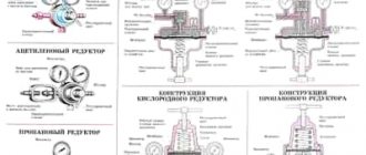
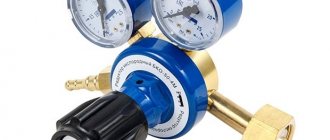
How does a cylinder reducer work:
1 Direct gearbox
An ordinary simple gas pressure reducing device consists of two chambers with an area of high and low pressure, separated by a rubber membrane. In addition, the “reducer” is equipped with an inlet and outlet fitting. Modern devices are designed in such a way that the bellows connection is screwed directly into the gearbox. Increasingly, you can find a gas reducer with a third fitting intended for mounting the monomer.
After gas is supplied through the hose and then through the fitting, it enters the chamber. The created gas pressure tends to open the valve. On the reverse side, a shut-off spring presses on the valve, returning it back to a special seat, popularly called a “saddle.” Returning to its place, the valve prevents the uncontrolled flow of high-pressure gas from the cylinder.
Membrane
The second acting force inside the gearbox is a rubber membrane that divides the device into high and low pressure areas. The membrane acts as an “assistant” to high pressure and, in turn, tends to lift the valve from the seat, opening the passage. Thus, the membrane is between two opposing forces. One surface is pressed by a pressure spring (not to be confused with the return spring of the valve), which wants to open the valve, on the other hand, the gas that has already passed into the low pressure zone presses on it.
The compression spring has manual adjustment of the pressure applied to the valve. We advise you to buy a gas reducer with a seat for a pressure gauge, this way it will be easier for you to adjust the spring pressure to the desired output pressure values.
As the gas leaves the reducer to the source of consumption, the pressure in the working space chamber decreases, allowing the pressure spring to straighten. She then begins to push the valve out of the seat, again allowing the device to be filled with gas. Accordingly, the pressure creeps up, pressing on the membrane and reducing the size of the pressure spring. The valve moves back into the seat, narrowing the gap, reducing the gas filling of the reducer. The process is then repeated until the pressure equalizes to the set value.
It should be recognized that gearboxes for direct type gas cylinders, due to their complex design, are not in high demand; reverse type gearboxes are much more widespread; by the way, they are considered devices with a high degree of safety.
2 Reverse gearbox
The operation of the device consists of the opposite action described above. Liquefied blue fuel is supplied to a chamber where high pressure is created. The bottled gas accumulates and prevents the valve from opening. To ensure gas flow into the household appliance, you need to turn the regulator in the direction of the right-hand thread.
On the back of the regulator handle there is a long screw, which, when screwed, presses on the pressure spring. As it contracts, it begins to bend the elastic membrane to the upper position. Thus, the transfer disk, through the rod, exerts pressure on the return spring. The valve begins to move and begins to open slightly, increasing the gap. Blue fuel rushes into the gap and fills the working chamber with low pressure.
In the working chamber, in the gas hose and in the cylinder, the pressure begins to increase. Under the influence of pressure, the membrane is straightened, assisted in this by a constantly compressed spring. As a result of mechanical interactions, the transfer disk lowers, weakening the return spring, which tends to return the valve to its seat. By closing the gap, the flow of gas from the cylinder into the working chamber is naturally limited. Then, with a decrease in pressure in the bellows liner, the reverse process starts.
In a word, as a result of checks and balances, the swing can be balanced and the gas reducer automatically maintains balanced pressure, without sudden jumps and drops.
Text of the book “Welding: A Practical Guide for Electric and Gas Welders”
2. Cylinders for compressed gases, valves for cylinders
Steel cylinders of small and medium capacity for gases for pressures up to 20 MPa (200 kgf/cm2) must comply with the requirements of existing regulatory documents.
Cylinders have different capacities of gases with a certain pressure. Cylinders with a volume of up to 12 dm3 (liters) are classified as small-capacity cylinders. Cylinders with a volume from 20 to 50 dm3 are classified as medium-capacity cylinders.
Cylinders intended for storage and transportation of compressed, liquefied and dissolved gases at temperatures from -50 to +60 ° C are made of seamless pipes.
Cylinders designed for operating pressures of 10, 15 and 20 MPa (100, 150 and 200 kgf/cm2) are made of carbon steel, and cylinders designed for operating pressures of 15 and 20 MPa (150 and 200 kgf/cm2) are made of alloy steel. become.
Oxygen cylinders are produced for a design pressure of 15 MPa (150 kgf/cm2), and acetylene cylinders are produced for a design pressure of 10 MPa (100 kgf/cm2).
The most common are cylinders with a capacity of 40 dm3.
Requirements for cylinders for compressed gases are regulated by the rules of Gosgortekhnadzor. The cylinders are painted on the outside in conventional colors, depending on the type of gas.
At the customer's request, the cylinders may not be painted. However, the mark must be clearly visible on the spherical part at the neck of the cylinder. In table 52 shows the conventional colors of the cylinders.
Table 52
Conventional colors for cylinders for storing and transporting various gases
Part of the upper sphere of the cylinder is not painted and passport data is stamped on it: trademark of the manufacturer; cylinder number; date (month, year) of manufacture and year of the next test, which are carried out every five years; weight of an empty cylinder in kg; cylinder capacity in dm3; OTK stamp.
Oxygen cylinders weigh 43.5 and 60 kg with a body length of 1390 mm. To calculate the amount of oxygen in a cylinder, you need to multiply the cylinder capacity in dm3 by the gas pressure in kgf/cm2, for example, with a cylinder capacity of 40 dm3 and a pressure of a cylinder filled with oxygen of 15 MPa (150 kgf/cm2), the amount of oxygen in the cylinder is 40 • 150 = 6000 dm3, or 6 m3. The structure of an oxygen cylinder is shown in Fig. 89, a.
Rice. 89.
Cylinders for compressed gases:
a
– oxygen;
b
– acetylene;
c
– (welded) for propane-butane;
1
– bottom;
2
– support shoe;
3
– body;
4
– neck;
5
– valve;
6
– cap;
7
– porous mass;
8
– nameplate;
9
– backing rings
The bottom of the cylinders rests on shoes to avoid impacts on the body during transportation and to ensure a stable vertical position when installed at the gas station. The upper part of the cylinders is also protected from accidental impacts by thick-walled caps.
The cylinder at the welding station is installed vertically and secured with a chain or clamp to prevent it from falling. During short-term installation work, the cylinder can be laid on the ground so that the valve is higher than the cylinder shoe; for this, the upper part of the cylinder is supported on a wooden lining with a cutout.
The cylinder is prepared for use in the following order: open the cap; unscrew the fitting plug; inspect the valve to make sure there are no traces of grease or oil.
If the presence of oil is noticed on the valve, then such a cylinder cannot be used and the welder must put this cylinder aside and inform the foreman or work supervisor about this.
If the valve is working properly, its fitting is blown out by briefly turning the handwheel at a small angle, while standing to the side of the valve fitting.
If the valve does not open or has a gas leak (poisoning), the cylinder should be set aside to be sent back to the oxygen plant for repair.
Next, check the condition of the reducer union nut and attach the reducer to the cylinder valve, then loosen the reducer adjusting screw.
By slowly rotating the handwheel, open the cylinder valve and set the operating oxygen pressure using the adjusting screw of the reducer. After this, you can select gas from the cylinder.
When the gas pressure in the reducer decreases, the gas cools. If the gas contains moisture, freezing of the valve and reducer channels may occur. In this case, the valve and reducer should be heated only with hot water or steam.
Acetylene cylinders for the safe storage of gas under high pressure are filled with a special porous mass of charcoal, pumice, infusor soil and impregnated with acetone, in which acetylene is highly soluble. Being in the pores of the mass, acetylene dissolved in acetone becomes explosion-proof and can be stored in a cylinder under pressure up to 2.5-3.0 MPa (25-30 kgf/cm2). The nominal pressure in the acetylene cylinder is set to 1.9 MPa (19 kgf/cm2) at 20 °C.
When the cylinder valve is opened, acetylene is released from the acetone and exits as a gas through the reducer into the burner hose. Acetone remains in the pores of the mass and again dissolves acetylene during subsequent filling of the cylinders with gas.
Acetylene from cylinders, compared to acetylene from a generator, provides greater safety during operation, has higher purity, contains less moisture, and provides higher gas pressure in front of the torch or cutter.
To determine the amount of acetylene, it is necessary to weigh the empty and filled cylinders. Empty cylinders should be stored with valves tightly closed to avoid leakage of acetone. The structure of an acetylene cylinder is shown in Fig. 89, b.
Propane-butane cylinders are made by welding from carbon steel sheets with a wall thickness of 3 mm and a capacity of 40 and 55 dm3; they are designed for a maximum operating pressure of 1.6 MPa (16 kgf/cm2). The design of a propane-butane cylinder is shown in Fig. 89, v.
Valves for oxygen cylinders are made of brass. Steel cannot be used for valve parts in contact with oxygen, as it is highly corroded in the environment of compressed moist oxygen. In an oxygen valve, due to accidental ingress of oil or ignition from friction of a homemade oil seal gasket, steel parts may catch fire, since steel can burn in a stream of compressed oxygen.
Rice. 90.
Valve for oxygen cylinder:
1
– gasket;
2
– spindle;
3
– spring;
4
– valve;
5
– coupling;
6
– handwheel
Brass does not burn in oxygen and is safe to use in oxygen valves. Handwheels, plugs and other valve parts are made of aluminum alloys or plastics.
The oxygen valve (Fig. 90) has a gland seal with a nylon gasket (1), into which the spindle (2) rests with a shoulder, pressed by a spring (3), and when the valve is open (4) by gas pressure. The rotation of the handwheel (6) is transmitted to the valve through a coupling (5) placed on the square shanks of the spindle and valve.
In Fig. Figure 91 shows another example of an oxygen valve - a membrane one. Membrane
(1)
made of phosphor bronze or stainless steel with a thickness of 0.1-0.15 mm. The valve is closed by the valve
(2)
.
Acetylene valves (Fig. 92) are made of steel, the use of which in this case is safe. On the contrary, it is prohibited to use copper and alloys containing more than 70% copper in acetylene valves, since acetylene can form an explosive compound with copper - acetylene copper.
The gearbox is connected to the acetylene valve with a clamp equipped with a screw. The spindle is rotated with a socket wrench placed on the square end of the spindle. Bottom of spindle (1)
has an ebonite insert and serves as a valve (2).
A set of leather rings is used to seal the oil seal (3). A felt filter (4) is inserted into the valve shank .
Different designs of oxygen and acetylene valves, as well as different colors of cylinders, prevent the possibility of mistakenly filling an oxygen cylinder with acetylene, and vice versa. An error poses a great danger, as it can lead to an explosion of cylinders when they are filled with the wrong gas for which they are intended.
Valves for propane-butane (Fig. 93) have a steel body (1),
valve
(2)
and spindle
(4),
connected by an elastic rubber cuff
(3),
which ensures the tightness of the stuffing box nut.
There are some features associated with the material of the cylinder valve body and the direction of the thread of the side fittings, which are given in table. 53.
Rice. 92.
Valve for acetylene cylinder:
1
– spindle;
2
– valve;
3
– stuffing box seal;
4
– filter
Rice. 93.
Valve for
propane-butane: 1
- frame;
2
– valve;
3
– rubber cuff;
4
– spindle
Rice. 91.
Membrane type valve:
1
– membrane;
2
– valve
Table 53
Materials of cylinder valve bodies and thread direction of side fittings
Control questions:
1. What capacities and pressures are cylinders made for storing and transporting compressed gases?
2. What colors are the cylinders painted in?
3. Tell us what you know about the design of cylinders?
4. What do you need to know about preparing cylinders for use?
5. Why do valves freeze and what should be used to defrost them?
6. Tell us what you know about oxygen valves?
7. How do oxygen valves differ from acetylene valves?
8. Explain the rules for storing cylinders at the welding station.
9. How is acetylene stored in cylinders?
10. What is the difference between a propane-butane cylinder and an acetylene cylinder?
3. Gearboxes, gas distribution ramps, sleeves (hoses), pipelines
Reducers serve to reduce the pressure of gas taken from a cylinder or gas pipeline and maintain this pressure constant, regardless of the decrease in gas pressure in the cylinder.
The industry produces single-chamber and double-chamber gearboxes. In two-chamber (two-stage) reducers, the pressure is reduced in two stages: in the first stage, the pressure is reduced from an initial value of 15 MPa (150 kgf/cm2) to an intermediate value of 4 MPa (40 kgf/cm2), and in the second - to a final operating pressure of 0. 3–1.5 MPa (3–15 kgf/cm2). Two-stage reducers provide almost constant gas pressure on the burner and are less prone to freezing, however, they are more complex in design than single-chamber ones and are much more expensive.
There are regulatory documents for gas reducers powering posts and installations for gas welding, cutting, soldering, surfacing, heating and other gas-flame processing processes. The service life of gearboxes is determined to be 4.5–7.5 years. 17 types of gearboxes are produced, but about 10 types are most widely used.
Gearbox brands are designated by letters and numbers. The letters carry the following information: B - cylinder, C - network, P - ramp, A - acetylene, B - hydrogen, K - oxygen, M - methane, P - propane, O - one stage with a spring setting, D - two stages with spring setting, Z – one stage with a pneumatic adjuster.
The numbers indicate the highest throughput of the gearboxes in m3/h. Each type of gearbox corresponds to one or more brands. Gearboxes are manufactured in accordance with existing regulatory documents for operation in various climatic conditions.
Cylinder and network reducers for oxygen, hydrogen and acetylene are used to operate at temperatures from -25 to +50 °C.
Cylinder and network reducers for propane and methane are used to operate at temperatures from -15 to +45 °C.
Ramp gearboxes are designed to operate at temperatures from plus 50 to minus 50 °C. The main parameters of the gearboxes used are shown in table. 54
Table 54
Main parameters of the gearboxes used
The gear housings are painted in the same color as the cylinders: oxygen – blue, acetylene – white, propane – red. Acetylene reducers operate similar to oxygen reducers. Their difference lies in the method of connection to the cylinder valve. This is also different from reducers used for other flammable gases.
Before connecting the reducer to the cylinder valve, it is necessary to blow out the valve fitting; Make sure that the gasket on the gearbox fitting and the threads of the gearbox union nut are in good condition and that they are free of contamination.
Having connected the reducer to the valve, completely loosen the adjusting screw of the reducer, and then open the cylinder valve, monitoring the readings of the high pressure gauge. The working pressure is set by rotating the adjusting screw clockwise. When the pressure reaches the specified value, you can release gas into the burner.
The sequence of actions for handling gearboxes is: (1) removing the valve; (2) valve purge; (3) securing the union nut; (4) setting the working pressure using a monometer.
During breaks in operation, it is necessary to loosen the gearbox spring, release the gas from the burner and rotate the gearbox adjusting screw counterclockwise until the gas pressure on the low pressure gauge is zero. After this, close the cylinder valve.
The gearbox pressure gauges must be in good working order and checked (see GOVERNOR'S stamp). Repair of gearboxes and pressure gauges is carried out only by specialized workshops or instrumentation laboratories of enterprises that have special equipment, trained and certified specialists and permission to carry out repair work from the State Metrological Service.
If oxygen consumption is significant, it should be supplied to the welding shop through a pipeline from a battery of oxygen cylinders. Gas distribution ramps are used for this purpose.
Cylinders are installed in one or two groups, connected by flexible copper tubes to pipes - manifolds through valves. Each manifold has a main shut-off valve. When gas is taken from one collector, new cylinders filled with gas are connected to the second. The valves allow you to disconnect each cylinder from the ramp without interrupting the gas extraction from the remaining cylinders. The ramp has a central reducer to reduce the pressure of the gas supplied to the workshop through the pipeline. Ramps are installed in a separate isolated room. Oxygen cylinders for pressures up to 15 MPa (150 kgf/cm2) are connected to the ramp with copper tubes with an outer diameter of 8 mm, a wall thickness of 1.5 mm and an internal diameter of 5 mm.
Distribution ramps also exist for acetylene cylinders. Clamps of acetylene gearboxes are attached to the collector steel pipe through armored flexible rubber-fabric hoses. A shut-off valve and a ramp acetylene reducer are installed on the manifold.
Sleeves (hoses) are used to supply gas to the burner or cutter. Rubber hoses for gas welding and metal cutting are manufactured according to specifications or international standard requirements. Specifications apply to rubber hoses with a thread frame used for supplying under pressure acetylene, city gas, propane, butane, liquid fuel and oxygen to tools for gas welding or metal cutting. The hoses are operational in areas with temperate and tropical climates at ambient temperatures from -35 to +70 °C and in areas with cold climates - from -55 to +70 °C.
Depending on their purpose, rubber hoses are divided into the following classes:
for supplying acetylene, city gas, propane and butane at a pressure of 0.63 MPa (6.3 kgf/cm2);
for supplying liquid fuel: A-72 gasoline, white spirit, kerosene or their mixture under a pressure of 0.63 MPa (6.3 kgf/cm2);
for supplying oxygen under pressure of 2 MPa (20 kgf/cm2) and 4 MPa (40 kgf/cm2). The main dimensions and minimum bending radius of the hoses are indicated in table. 55.
Table 55
Main dimensions and minimum bending radius of sleeves
Example of a symbol: Hose 1-16-0.63 GOST 9356-75 (I – class; 16 – internal diameter in mm; 0.63 MPa – working pressure; for work in temperate climates).
If the word GOST is preceded by the letter T, then such hoses are used for work in areas with a tropical climate, if the letters KHL are used for work in areas with a cold climate.
Depending on the purpose of the sleeve, its outer layer should be tinted near the marking site in the appropriate color:
red color – class I hose for acetylene, city gas, propane and butane;
yellow color – class II hose for liquid fuel;
blue color – class III hose for oxygen.
An outer layer of black color is allowed for hoses of all classes operating in areas with tropical, temperate and cold climates, as well as designation of the hose class with two rubber colored stripes on the outer layer for all climatic areas or two risks. Oxygen hoses with a black outer layer are not marked with a hose class designation.
Each sleeve is marked along its entire length at intervals using embossing and colored paint.
Pipelines for supplying acetylene are laid from seamless steel pipes connected by welding. The acetylene pipeline is painted white. The dimensions of pipes for low pressure acetylene are given in table. 56.
Table 56
Pipe sizes for low pressure acetylene pipeline supplied to welding stations
The internal diameter of the medium pressure acetylene pipeline 0.01–0.15 MPa (0.1–1.5 kgf/cm2) should not exceed 50 mm; high pressure acetylene pipeline over 0.15 MPa (1.5 kgf/cm2) – no more than 20 mm. When gas flow is high, two or more parallel pipelines are laid.
The pipeline is laid along walls and columns at a height of at least 2.5 m from the floor.
To drain condensate, the pipeline is given a slope of 0.002 towards the moisture collector. Branches from the main pipe to the gate valves are made from pipes with an internal diameter of 13 mm (1/2 inch).
Pipelines for oxygen under a pressure of 1.50 MPa (15 kgf/cm2) are made of steel gas welded (reinforced), seamless or electric-welded pipes. At a pressure of 1.5–6.4 MPa (15–64 kgf/cm2), only seamless steel pipes are used. At pressures above 6.4 MPa (64 kgf/cm2), copper or brass seamless pipes are used, since at high pressure a steel pipe may ignite in oxygen from a spark due to friction of scale particles on the walls of the pipe, accidental ingress and self-ignition of oil, and gaskets catching fire and other phenomena associated with local heat release.
Oxygen lines are painted blue. When laying an oxygen pipeline in the ground, seamless steel pipes are used, regardless of gas pressure.
Pipes for oxygen are connected to each other by welding; for copper pipes, joints are soldered with hard copper-zinc solder into the socket or on couplings.
All pipes for oxygen supply after installation, before putting into operation, must be degreased by washing with a solvent (carbon tetrachloride), followed by blowing with steam or dry air, cleared of oil vapors, until the solvent is completely removed (odor disappears).
When laying together, the oxygen line is located below the acetylene line, with a distance between them of at least 250 mm and a height from the floor level of at least 2.5 m.
To supply oxygen to welding stations at low pressure 0.5-1.0 MPa (5-10 kgf/cm2), the diameter of the oxygen pipeline is selected according to the table. 57.
Table 57
Pipe sizes for the low pressure oxygen pipeline supplied to the welding stations
Control questions:
1. What is the purpose of gearboxes and the principles of operation of a single-chamber gearbox?
2. What is the difference between a two-chamber gearbox and a single-chamber gearbox?
3. How are gearbox brands identified?
4. What are the requirements for gearboxes based on climatic conditions?
5. What colors are gearboxes painted and why?
6. Explain the rules for handling gearboxes.
7. Explain about oxygen cylinder ramps.
8. How do acetylene cylinder ramps differ from oxygen cylinders?
9. Tell us about sleeves (hoses).
10. What do you know about oxygen and acetylene pipelines?
4. Welding torches
The welding torch serves as the main tool for manual gas welding. In the burner, oxygen and acetylene are mixed in the required quantities. The resulting combustible mixture flows from the channel of the torch mouthpiece at a given speed and, when burned, produces a stable welding flame, which melts the base and filler metal at the welding site. The burner also serves to regulate the thermal power of the flame by changing the flow of combustible gas and oxygen. According to the method of supplying oxygen, flammable gas and the design of their mixing unit, two types of burners are used: injection and non-injector (Fig. 94).
In an injection burner, the mixing chamber begins with a small cylindrical section, smoothly turning into a more elongated conical section.
Injector burners operate on low and medium pressure acetylene. Acetylene is supplied to the mixing part of the injection burner by sucking it with a stream of oxygen emerging at high speed from the nozzle hole called the injector. The process of sucking gas of lower pressure into a stream of gas supplied at higher pressure is called injection.
Rice. 94.
Design of a gas mixing unit in burners:
A
– injection;
b
– non-injector;
1
– oxygen channel;
2
– acetylene channel;
3
– injector nozzle;
4
– mixing chamber;
5
– fuel mixture tube
The diagram of the injection burner assembly or mixing chamber is shown in Fig. 94, a.
Oxygen under pressure enters through channel (1) into the injector nozzle
(3).
When oxygen flows out of the nozzle at high speed, a vacuum is created in channel (2), through which acetylene is sucked in.
Oxygen and acetylene enter the mixing chamber (4),
having a conically expanding channel (diffuser), where they mix and form a combustible mixture, which goes through the tube (5) into the torch mouthpiece, forming a welding flame at the exit from it during combustion.
The diagram of the mixing unit of an injectionless burner is shown in Fig. 94, b. In this burner there is oxygen through channel (1) and combustible gas (acetylene) through channel (2)
enter under equal pressure into the cylindrical channel of the mixer
(4),
combine in it into a combustible mixture, which is directed through the tube
(5)
into the burner mouthpiece, forming a flame at the outlet.
For normal operation of the injection burner, the pressure of oxygen entering it must be 0.2-0.4 MPa (2-4 kgf/cm2), and acetylene - from 0.001 to 0.01 MPa (0.01-0.1 kgf/cm2 ).
To create the necessary vacuum in the burner, the distance between the end of the injector nozzle and the entrance to the mixing chamber is essential.
As this distance increases to the injection limit, the suction increases, and as it decreases, it decreases. Stable flame combustion with a normal composition of the mixture for acetylene-oxygen burners and mouthpieces is ensured when the mixture flow rate from the mouthpiece nozzle is in the range of 50-170 m/s (for mouthpieces with an outlet channel diameter of 0.6-3.5 mm). In this case, the excess pressure of the mixture in the tube in front of the mouthpiece should be in the range of 0.003-0.027 MPa (0.03-0.27 kgf/cm2).
At a mixture flow rate of 20–40 m/s, pops and reverse flame impacts occur, and at a speed of up to 140–240 m/s, the flame can break off from the burner mouthpiece.
Injection burners can operate at an average acetylene pressure of up to 0.15 MPa (1.5 kgf/cm2). However, when operating from an acetylene cylinder with an injection burner, the acetylene pressure in front of it must be maintained within the range of 0.02–0.05 MPa (0.2–0.5 kgf/cm2), which reduces the possibility of popping and backfire.
For better heat dissipation, mouthpieces are made of highly thermally conductive materials - MZ grade copper or Br.XO.5 chromium bronze. Splashes of molten metal adhere to these materials to a lesser extent. The mouthpieces of low-power water-cooled burners are made of leaded brass LS59-1.
For stable combustion and the correct shape of the flame, careful processing of the surface of the outlet channel of the mouthpiece is required. Burrs, dents, and other damage may cause flame separation, popping, or kickback. The outside of the mouthpieces is polished to a mirror finish to prevent the adhesion of metal spatters.
The injection device of the burner provides a certain “reserve of acetylene,” i.e., an increase in its flow rate when the acetylene valve of the burner is fully open compared to the nominal gas flow rate for a given mouthpiece number. Burners provide an acetylene supply of up to 15%, and cutters - up to 10% of the maximum gas flow.
Various burners are used in production, differing in design, power and purpose. The most common universal welding torches are of medium power, and for body repair work - low power.
The torches are equipped with a set of replaceable tips of various sizes, differing in gas flow and intended for welding metal of various thicknesses.
The tip number is selected in accordance with the thickness of the metal being welded and the required specific acetylene consumption in dm3/h per 1 mm of thickness. In table 58-62 show the technical characteristics of the most common low- and medium-power burners.
Table 58
Technical characteristics of injection burners
Table 59
Welding torches for acetylene substitute gases
* Burner GZU-3 – universal; GZU-4 – for welding cast iron and non-ferrous metals (except copper), as well as surfacing, soldering, heating.
Table 60
Table 61
Universal acetylene-oxygen torches
* Burner type G1 is non-injector, other types are injection. ** The GS-4 burner is intended for heating, the G2-04 burner is similar in design to the previously produced G2-02, “Zvezdochka”, “Malyutka” burners; The GZ-03 burner replaced the produced Zvezda, Moskva, GS-3, GS-3A burners.
Table 62
Technical characteristics of injectionless burners type G1
Single-flame universal burners for oxy-acetylene welding, soldering and heating are manufactured in accordance with existing regulatory documents, which provide for four types of burners: G1 – micro-power burners, injection-free; G2 – low power injection burners; G3 – medium power burners, injection; G4 – high power injection burners.
Low power burner G2 is supplied with nozzles No. 0; 1; 2; 3; 4. The set of G3 medium power burners includes a barrel and seven tips attached to the burner barrel with a union nut. The low-power torch is designed for welding thin metals and works with a hose with a diameter of 6 mm.
The welder usually has to work with torches of different power, so it is necessary to provide a hose connector for moving from a low-power torch to a medium-power torch. The hoses have an internal diameter for the burner fitting of 6 and 9 mm. When changing burners, the hoses are changed; adapters are used for this - nipples 6 and 9 mm.
For the propane-butane-oxygen mixture, burners of the GZU-3 and GZM-4 types are produced. The first is intended for welding steel 0.5-7 mm, the second is for heating the metal. For gas-flame cleaning of metal surfaces from rust, old paint, etc., GAO-2 acetylene-oxygen burners are produced. The width of the surface processed by the burner in one pass is 100 mm.
Various types of burners are widely used in production: acetylene burners “Iskra-BM”, acetylene burners G-3 “Donmet”, propane burners “Iskra-6VP”, GV “Termika-10”, etc.
A serviceable, correctly assembled and adjusted torch should produce a normal, stable welding flame. If the burning is uneven, the flame comes off the mouthpiece, goes out, or gives back strokes and pops, you should carefully adjust the oxygen and acetylene supply with the valves. If after adjustment the problems are not eliminated, then they are caused by malfunctions in the burner itself: leaks in connections, damage to the outlet channel of the mouthpiece or injector, incorrect installation of burner parts during assembly, clogged channels, wear of parts, etc.
Before starting work, check the serviceability of the burner.
To check the injector, put a hose on the oxygen nipple, and insert a tip into the burner body, the union nut of which is smoothly tightened with a wrench.
Having set the oxygen pressure in accordance with the tip number, oxygen is released into the burner by opening the oxygen valve. A vacuum should form in the acetylene nipple of the torch, which can be easily detected by placing a finger on the nipple hole, which should be suctioned. If there is suction, the burner is working.
If there is no suction, you should check:
Is the injector pressed tightly enough to the seat of the burner body? If a leak is detected, the injector should be moved until it rests against the seat with the tip inserted into the barrel;
whether the channels of the mouthpiece, mixing chamber and acetylene tube are clogged. If clogged, it is necessary to clean the channels with thin copper wire and blow them out.
After checking the burner, connect both hoses, secure them to the nipples with clamps and ignite the combustible mixture.
If, when igniting the mixture, the burner makes a popping sound or when the acetylene valve is fully opened, excess acetylene does not appear in the flame (black soot), it is necessary to check whether the union nut of the tip is tightened well, whether the oxygen pressure is sufficient and whether there are any obstacles to the flow of acetylene into the burner (water in the hose , bending the hose, pressing the hose with parts, twisting the hose, etc.).
When the burner stops working, as well as when there are frequent pops or backfires, you must first close the acetylene valve, then the oxygen valve.
Sometimes frequent pops and kickbacks are caused by the mouthpiece overheating after prolonged use. In this case, it is necessary to extinguish the burner flame in the order mentioned and cool the burner mouthpiece in a handy vessel with water.
The injection burner operates normally and reliably if the ratio of the diameters of the injector channels, mixing chamber and mouthpiece are selected correctly.
If the mouthpiece is burnt, has nicks and its hole is heavily developed, the end of the mouthpiece should be carefully filed with a small file, lightly caulked or hammered, and then calibrated with a drill of the appropriate diameter (see Table 60). The surface of the mouthpiece must be polished.
Gas leaks through the burner valve seals are eliminated by replacing the seal packing or tightening the seal nuts.
Control questions:
1. What is the purpose of a welding torch?
2. What is the difference between injection and non-injector burners?
3. What is the purpose of the injector?
4. What happens to the burner flame when the flow rate of the combustible mixture increases excessively?
5. Why do pops and kickbacks occur?
6. Why is careful mouthpiece care required?
7. What types of burners are there?
8. What are the G2 and G3 burners equipped with?
9. Tell us about adjusting burners in case of malfunction.
Hands off!
First, about the prohibitions. Yes, dear reader, I have no doubt that you are full of enthusiasm and are eager to carry out the transfer of the gas pipe in the kitchen yourself. However, please take the restrictions I have listed as seriously as possible:
You cannot move the gas riser in the kitchen. All you can do is change where the tap attaches to it or the length of that tap;
Polyethylene and plastic pipes in general should not be used indoors. SNiP 2.04.08-87 in paragraph 4.85 directly states that polyethylene is prohibited for laying in residential buildings, and in paragraph 6.2 it states what materials should be used;
Do not close general plug valves, ball valves and valves on gas supply inlets and risers. If at the time you turn off the gas, someone is cooking food, the fire will go out, and after starting it will continue to flow into the kitchen. The result of such a development of events is usually described in TV reports by random witnesses: there is no one among the residents to tell about it;
Finally, the main thing: PB (safety rules) 12-368-00 prohibit any gas-hazardous work carried out by persons who have not undergone instructions and exams on safe work methods.
Simply put: only a representative of Gorgaz or a licensed gas equipment servicing company should connect any gas appliances.
What will happen
If you are incredibly lucky and, without the necessary knowledge and practical experience, prevent a gas leak, your amateurishness will be revealed during the first scheduled inspection of gas equipment by representatives of the gas service.
The consequences are unpredictable: they can either turn a blind eye to the work you have done or draw up a report on an administrative offense that endangered the life and health of people.
Worst case scenario... Comrades, I won’t spoil your mood. Everyone knows what a gas explosion in a residential building is.
It should be noted: the gas pipeline has relatively low pressure (unlike, for example, a water supply). Based on this, there is no need to shut off the entire gas network. However, safety measures still need to be taken. First of all, the window must be open when carrying out work. The doors to the kitchen should be tightly closed, and the cracks should be plugged with rags or towels.
We begin the work by dismantling the used gas tap. We remove it using a gas wrench. As soon as the faucet is removed, we plug the pipe with a thumb pad. At this time, the assistant screws FUM tape onto the new faucet or applies sealant to the threaded connection.
Next you need to make sure the connection is tight. To do this, use the old proven method with a soap solution. A soapy solution should be applied to the connection and if bubbles appear, the connection will leak. The defect must be corrected immediately: remove the tap and repeat sealing the connection.
Read more: Self-clamping terminal blocks: types and features of using selection rules
At the end of the work, you should thoroughly ventilate the kitchen area and connect the gas stove to the system. Even in the absence of professional skills, the operation to replace a gas tap takes no more than 15 minutes. The advantage of doing the work yourself is significant cost savings. However, if you do not have confidence in your own abilities, it is better to entrust this work to specialists from the gas supplier’s service department.
Purpose of the gas valve
PSK is a safety valve element responsible for the safety of the gas pipeline and gas equipment connected to it. During operation, the valve is in a closed position, therefore it is classified as a closed pipe fitting.
Such devices are installed not only on gas pipelines, they are an integral part of other communications - water supply, heating networks. Everywhere they perform the same function - they stabilize the pressure in the network, provide the operating parameters necessary for the proper functioning of the system.
The valve serves to relieve excess gas if pressure parameters become critical. Fuel that creates an imbalance in the system is discharged into an auxiliary pipeline or discharged into the atmosphere
The pressure surge is usually short-lived and depends on a number of factors.
Reasons that can cause excess pressure in the system:
- breakdown of connected gas equipment - double-circuit boiler, instantaneous water heater or capacitive boiler, shut-off valves;
- use of fuel of inappropriate composition;
- change in temperature indicators in the pipeline;
- failure in the thermal-mechanical circuit.
The installation location of the gas safety valve is standard, depending on the efficiency of the application: either in the pressure regulator, or immediately behind it. After automatic operation of the valve, it returns to its operating – closed state.
In a gas network, the valve is a separate device or integrated into the pressure regulator. It is triggered if the operating gas pressure exceeds the nominal level by 15%
What are the consequences of the absence of a PSK on the network? The most common consequences are mechanical destruction of the pipeline or breakdown of connected equipment, which can cause a gas leak.
There is also a possibility of an explosion, so it is necessary to constantly monitor the serviceability of the device, carry out timely maintenance and replace failed elements
Along with relief devices, gas safety shut-off valves are also used, with the help of which the fuel supply is shut off. This happens automatically. The shut-off valve element is installed on the pipeline, in the gap between the filter and the pressure regulator.
The operating limit of the SPD is indicated in the technical data sheet of the device. The upper critical parameter is usually equal to the formula: slave. pressure +25%.
Types of plates for gas cylinders
It’s worth saying right away that there are gas stoves that can work with both main natural gas and bottled liquefied gas. Reconfiguration requires replacement of nozzles and adjustment. So, in principle, any of them is suitable for a dacha.
Tabletop gas stoves are mobile... why not...
Another thing is that in “field” conditions it is used much less and less often than in everyday life. For this reason, the simplest and smallest models are chosen. After all, now water for tea is most often heated with an electric kettle, and prepared food is heated in a microwave oven. They only cook on the gas stove at the dacha, and even the simplest dishes. Some housewives also make twists. That's all. That’s why they usually buy one or two burner stoves. However, there is a fairly wide selection to suit any requirements and needs.
Table and floor
According to the installation method, gas stoves for dachas are divided into tabletop and floor-mounted. Technical characteristics do not differ only in dimensions. Desktop ones are usually made the simplest, without any additional options. This is exactly a country/hiking option with minimal weight and dimensions.
For rare visits, “this will do”, but you can’t place the cylinder next to it
Which gas stove is better for a summer cottage under a cylinder? Tabletop or floor-standing? It's all about the availability of free space. If you have somewhere to install a floor-standing option, take it. Even if they are more expensive, they themselves can serve as a cabinet. And there are usually not enough of them (cabinets) at the dacha. Just remember that you still need to find a place to store the cylinder. It can be located nearby (the minimum distance between the stove and the cylinder is 0.5 meters and at a distance of at least 1 meter from the heating devices), or it can stand on the street in a special cabinet that is locked with a key.
If, on the contrary, there is space on the table, but not on the floor, a tabletop version of a gas stove will do. The best part is that they cost one and a half to two thousand rubles.
Number and type of burners
A gas stove for a summer cottage under a cylinder can have from one to four burners. A single-burner is suitable if there are only one or two people at the dacha and you don’t do any twisting. To prepare breakfast/dinner for a family of three to four people and a small amount of preserves, two burners are enough. Well, if you need it and dinner for a full family, take it with three or four burners.
Options for tabletop gas stoves for a summer cottage under a cylinder
Recently, in addition to standard, medium-sized burners, they began to make even larger and smaller ones. This is convenient, since dishes come in different diameters. Such “excesses” are available only on four-burner options.
In addition, there are models that have electric burners in addition to gas burners. If there is light in the area, and you need a stove for your cottage with a cylinder for three or four burners, this is also convenient. The gas in the cylinder tends to run out at the most inopportune moment. If you don't have a spare one, at least start a fire. And if you have an electric burner, you can finish the process and hold out until the cylinder is filled.
Availability of additional options
The range of additional functions just for gas burners is small. These are electric or piezo ignition and gas control. Both functions are useful, but how necessary it is is up to you to judge. It’s worth saying right away that they are very rare in desktop versions.
Gas tabletop stove with electric oven underneath
Where is bottled oxygen used?
Compressed oxygen has found application in many areas:
- Metallurgy: it is used to improve the quality of metal and increase the productivity of smelting furnaces.
- Chemical industry: production of acids. Liquefied gas is used to produce explosives.
- Aviation: fuel oxidation in engines.
- Medicine: replenishing oxygen deficiency, treating cardiovascular diseases and asthma.
- Fishing industry: enrichment of water bodies.
- Construction: when cutting metal surfaces and welding them.
- Pulp and paper industry: oxygen in cylinders is required for pulp cleaning and paper bleaching.
- Science: conducting research.
how many cubic meters are in a 50 liter liquefied gas cylinder?
Answer: 5 cubes.
How many cubes are 1000 liters? Answer: 1 cubic meter. 10000 liters how many cubes? Answer: 10 cu. m. 140 liters is how many cubes? Answer: 0.14 cubic meters. 1500 liters how many cubes? Answer: 1.5 cubic meters.
To simplify the calculations, we suggest you use our online calculator for converting liters to cubes, but you can always do it yourself by using a regular calculator to convert cubes to liters or liters to cubes.
| Author | Message |
| Hello ! I ask the moderators not to scold me yet, I don’t know where else to ask. I bought a couple of empty freon cylinders and want to make a small air receiver. The compressor is also from a domestic refrigerator. What pressure can these cylinders withstand? so don't rush!!! I looked through your forum on refrigerator accessories and did not find the answer. but I found a photo of the cylinders. |