Indication of the slope on the roof plan
Angular dimensions are indicated on the drawings in degrees, minutes and seconds with the designation of the unit of measurement ( GOST 2.307-2011 “Unified system of design documentation (ESKD). Drawing dimensions and maximum deviations “).
In accordance with GOST R 21.1101-2013 “System of design documentation for construction (SPDS). Basic requirements for design and working documentation” , on the plans the direction of the slope of the planes is indicated by an arrow, above which, if necessary, the numerical value of the slope is indicated as a percentage or as a ratio of the unit height of the plane to the corresponding horizontal projection. It is allowed to indicate the numerical value of the slope in ppm or as a decimal fraction accurate to the third digit.
On sections, sections and diagrams, a sign is placed in front of the dimensional number that determines the numerical value of the slope,
the acute angle of which should be directed towards the slope (except for the steepness of the slopes of embankments and excavations). The slope designation is applied directly above the contour line or on the shelf of the leader line.
Also, instead of the angle sign, the letter designation of the slope ( i ) is also found in the drawings.
Percentages usually indicate the slope angles of roofs, ramps, flights of stairs, etc.
To determine the slope angle in percent (%) (see drawing 1) you need: 0.2 m / 4 m x 100 = 5% .
To determine the slope angle in ppm (‰) it is necessary: 0.2 m / 4 m x 1000 = 50 ‰ .
The same slope value can also be designated as the ratio of the height to the length of the horizontal section — 1:20 (4 / 0,2 = 20).
The dimensions for the slope angle expressed in ppm are calculated in a similar way, only instead of dividing by 100 , dividing by 1000 .
Note: in order to enter the ppm symbol ( ‰ ) on the computer, you must turn on NumLock , press the Alt 0137 on the numeric keypad , release the Alt after which the ‰ .
Source
Construction Features - Construction of slope and taper
Contents of the material
- Construction Features
- Dividing a circle
- Connecting lines
- Box curved lines
- Constructing slope and taper
- Pattern curves
- All pages
CONSTRUCTION OF SLOPE AND TAPER
CONSTRUCTION AND DESIGNATION OF SLOPE
Slope is the quantity that characterizes the inclination of one straight line to another straight line. Slope is expressed as a fraction or percentage.
The slope i of segment BC relative to segment BA is determined by the ratio of the legs of the right triangle ABC (Fig. 69, a), i.e.
To construct a straight line BC (Fig. 69, a) with a given slope to a horizontal straight line, for example 1:4, it is necessary to lay off a segment A B equal to four units of length from point A to the left, and a segment AC equal to one unit of length upward. Points C and B are connected by a straight line, which gives the direction of the desired slope.
Slopes are used when drawing parts, for example, steel beams and rails produced on rolling mills, and some parts made by casting (Fig. 69, e).
When drawing the contour of a part with a slope, first a slope line is drawn (Fig. 69, c and d), and then a contour.
If the slope is specified as a percentage, for example, 20% (Fig. 69, b), then the slope line is constructed in the same way as the hypotenuse of a right triangle. The length of one of the legs is taken equal to 100%, and the other - 20%. Obviously, a slope of 20% is otherwise a slope of 1:5.
According to GOST 2.307-68, in front of the dimensional number that determines the slope, a symbol is applied, the acute angle of which should be directed towards the slope (Fig. 69, c and d).
Learning to read drawings. Roof
The roof is the upper part of almost any structure, protecting it from atmospheric influences. Therefore, when drawing up estimates for the construction of residential, public and industrial buildings, it is necessary to determine the cost of roofing work. Along with selecting prices, the estimator is faced with the task of calculating the volume of work, which can only be realized by studying the design documentation in detail.
A certain standard of data has been approved, which must be indicated in the project documentation. According to the rules of SP 17.13330.2017 “Roofs. Updated edition of SNiP II-26-76" (clause 4.14) in the working drawings of the roof of buildings it is necessary to indicate:
“- roof plan, its design solution, name and brands of materials and products with links to regulatory documents;
- the value of the slopes, the installation location of drainage funnels and the location of expansion joints;
— details of roofs in places where drainage funnels are installed, drainage gutters and junctions with walls, parapets, ventilation and elevator shafts, cornices, pipes, roof windows and other structural elements;
— fastening of corrugated sheets and corrugated profiles through the upper crest of the wave and corrugation using a sealing gasket.”
As you can see, not a word about the volume of construction and installation work on the roofing. And this is not surprising, because MDS 12-33.2007 “Roofing works” states (clause 3.1):
“Roofing work is carried out, as a rule, according to a work project or according to technological maps.”
And if from the Methodological Recommendations for the development and execution of a construction organization project and a work execution project MDS 12-81.2007, it can be understood that a bill of quantities for construction work is developed as part of a construction organization project (clause 5.4).
The most informative drawings for calculating the volume of roofing work are the roof plan and sections of the building. In some cases, installation diagrams for rafter structures may be needed.
The roof plan is a drawing of the horizontal projection of the roof, i.e. its projection onto the plane of the floor or earth. The most important indicator on the roof plan is its slope.
One dimension (%) of the roof slope is converted to another (degree) using the formula:
where α is the angle of inclination of the roof
Consider the roof plan of a three-apartment residential building.
The drawing indicates that the roof slope is 25°. In this case, all roof slopes have the same slope. However, there are also roofs of complex structures, for example attic type, the elements of which have different degrees of inclination relative to the horizon.
Two chimneys pass through the roof: in axes 1-2/G and 3/V-G. However, when calculating the volume of work, we do not take them into account, because according to the rules of the section “Calculation of the scope of work” of the GESN collection 81-02-12-2017 Roofing:
"2.12.1. The scope of roofing work should be calculated based on the full coverage area according to the design data, without deducting the area occupied by dormers and chimneys and without taking into account their lining.”
The cornice extension is 600 mm. This value is defined as the distance between the outer contour of the building and the outer plane of the wall, shown in the drawing with a dotted line.
Please note that the building has an axis of symmetry near the coordination axis G, therefore the roofing consists of mirror elements equal in area.
The total roof area is determined as the sum of its constituent elements: triangles, trapezoids and inclined parallelepipeds. The areas of each figure are determined using geometry formulas. The initial data are the lengths of the bases and the heights of the figures.
When determining these values, it is important to remember the following:
The roof plan is made according to traditional design rules: i.e. linear dimensions are indicated on it!
Sloping elements (roof slopes) are indicated in a horizontal projection, which means they are depicted on the drawing with distortion! Therefore, the height cannot be read from the roof plan to determine the area of geometric shapes! For these purposes, trigonometry formulas and additional data from sections of the building are used.
As you can see, when reading roofing drawings, despite their apparent simplicity, there are many nuances that require certain knowledge and extreme care!
Source
What is slope? How to determine slope? How to build a slope? Designation of slope on drawings according to GOST.
Slope . Slope is the deviation of a straight line from a vertical or horizontal position. Determination of slope. The slope is defined as the ratio of the opposite side of the angle of a right triangle to the adjacent side, that is, it is expressed by the tangent of the angle a. The slope can be calculated using the formula i=AC/AB=tga.
Construction of the slope . The example (Figure) clearly demonstrates the construction of a slope. To construct a 1:1 slope, for example, you need to lay out arbitrary but equal segments on the sides of a right angle. This slope will correspond to an angle of 45 degrees. In order to construct a slope of 1:2, you need to set aside a horizontal segment equal in value to two segments laid down vertically. As can be seen from the drawing, the slope is the ratio of the opposite side to the adjacent side, i.e. it is expressed by the tangent of the angle a.
What is the roof pitch angle measured in?
In SNiP II-26-76, this value is indicated as a percentage (%). At the moment, there are no strict rules for indicating the size of the roof slope.
The unit of measurement for roof slope is degrees or percentages (%). Their ratios are shown in the table below.
Roof slope degree-percentage ratio
| degrees | % | degrees | % | degrees | % |
| 1° | 1,75% | 16° | 28,68% | 31° | 60,09% |
| 2° | 3,50% | 17° | 30,58% | 32° | 62,48% |
| 3° | 5,24% | 18° | 32,50% | 33° | 64,93% |
| 4° | 7,00% | 19° | 34,43% | 34° | 67,45% |
| 5° | 8,75% | 20° | 36,39% | 35° | 70,01% |
| 6° | 10,51% | 21° | 38,38% | 36° | 72,65% |
| 7° | 12,28% | 22° | 40,40% | 37° | 75,35% |
| 8° | 14,05% | 23° | 42,45% | 38° | 78,13% |
| 9° | 15,84% | 24° | 44,52% | 39° | 80,98% |
| 10° | 17,64% | 25° | 46,64% | 40° | 83,90% |
| 11° | 19,44% | 26° | 48,78% | 41° | 86,92% |
| 12° | 21,25% | 27° | 50,95% | 42° | 90,04% |
| 13° | 23,09% | 28° | 53,18% | 43° | 93,25% |
| 14° | 24,94% | 29° | 55,42% | 44° | 96,58% |
| 15° | 26,80% | 30° | 57,73% | 45° | 100% |
Roof slope measurement
The slope angle is measured using an inclinometer or mathematically.
Mathematical calculation of slope
You can calculate the roof slope without using geodetic and other instruments for measuring the slope. To do this you need to know two sizes:
Using mathematical calculation, the roof slope is found as follows:
The slope angle i is equal to the ratio of the roof height H to the ground level L
In order to express the value of the slope as a percentage, this ratio is multiplied by 100. Next, to find out the value of the slope in degrees, we translate using the table of ratios located above.
To make it clearer, let's look at an example:
Laying length 4.5 m, roof height 2.0 m.
Source
GOST R 21.1101-2013 SPDS. Basic requirements for design and working documentation
This GOST establishes the basic requirements for design and working documentation for the construction of facilities for various purposes.
Requirements for applying dimensions are specified in section 5.4 of GOST R 21.1101-2013.
5.4 Applying dimensions, slopes, marks and inscriptions
5.4.1 Linear dimensions in the drawings are indicated without units of length:
5.4.2 The dimension line at its intersection with extension lines, contour lines or center lines is limited by serifs 2-4 mm long, applied with an inclination to the right at an angle of 45° to the dimension line, while the dimension lines continue beyond the outer extension lines (or, respectively, beyond contour or axial) by 0-3 mm.
When applying a diameter or radius dimension inside a circle, as well as an angular dimension, the dimension line is limited by arrows. Arrows are also used when drawing dimensions of radii and internal fillets.
When drawing dimensions on axonometric diagrams of process pipelines and engineering systems, dimension lines may be limited by arrows.
5.4.3 Markings of levels (height, depth) of structural elements, equipment, pipelines, air ducts, etc. from the reference level (conventional “zero” mark) are indicated in meters without indicating a unit of length with three decimal places separated from the whole number by a comma, beyond except in cases specified in the relevant SPDS standards.
Level marks on facades, sections and sections are placed on extension lines (or on contour lines) and are indicated with the sign “
“, made with solid thin lines with a stroke length of 2-4 mm at an angle of 45° to the extension line or contour line, in accordance with Figure 5; on plans - in a rectangle in accordance with Figure 6, except for cases specified in the relevant SPDS standards.
Figure 5
Figure 6
The “zero” mark, usually accepted for the surface of any structural element of a building or structure located near the planning surface of the earth, is indicated without a sign; relative marks above zero are indicated with a “+” sign, below zero - with a “-“ sign.
Note - As a rule, the level of the finished floor of the first floor is taken as the zero level for buildings.
5.4.4 On the plans, the direction of the slope of the planes is indicated by an arrow, above which, if necessary, the numerical value of the slope is indicated as a percentage in accordance with Figure 7a or as the ratio of the unit height of the plane to the corresponding horizontal projection (for example, 1:7).
Figure 7
It is allowed to indicate the numerical value of the slope in ppm or as a decimal fraction accurate to the third digit.
On sections, sections and diagrams, the sign "" is placed in front of the dimensional number that determines the numerical value of the slope.
“, the acute angle of which should be directed towards the slope (except for the steepness of the slopes of embankments and excavations). The slope designation is applied directly above the contour line or on the shelf of the leader line in accordance with Figure 7b.
Slopes. Construction, designation.
Slope is the deviation of a straight line from a vertical or horizontal position. Slope is defined as the ratio of the opposite leg of the angle of a right triangle to the adjacent leg, that is, it is expressed by the tangent of the angle a. The slope can be calculated using the formula i=AC/AB=tga.
Construction of the slope. The example (Figure) clearly demonstrates the construction of a slope. To construct a 1:1 slope, for example, you need to lay out arbitrary but equal segments on the sides of a right angle. This slope will correspond to an angle of 45 degrees. In order to construct a slope of 1:2, you need to set aside a horizontal segment equal in value to two segments laid down vertically. The slope is the ratio of the opposite side to the adjacent side, i.e. it is expressed by the tangent of the angle a. The designation of slopes in the drawing is carried out in accordance with GOST 2.307-68. The amount of slope is indicated on the drawing using a leader line. The sign and magnitude of the slope are indicated on the leader line shelf. The slope sign must correspond to the slope of the line being determined, that is, one of the straight lines of the slope sign must be horizontal, and the other must be inclined in the same direction as the slope line being determined. The slope of the sign line is approximately 30°.
3. . GOST 2.303-68* Types of lines. Parameters, application.
GOST 2.303-68* for use in IG establishes 9 types of lines, the parameters of which are determined from the selected parameter of the main solid thick line, the thickness of which is taken from 0.5 to 1.4 mm depending on the size, complexity of the image and format.
They are used, for example, to depict threads, splines, etc.; the corresponding ESKD standards are established.
Ticket 26
1..Direct projecting.
(perpendicular to any projection plane); a)
horizontally projecting (perpendicular to P1);
b)
front-projecting (perpendicular to P2);
c)
profile-projecting (perpendicular to P3).
2.Taper. Construction, designation.
Taper is the ratio of the diameter of the base of the cone to the height. The taper is calculated using the formula K=D/h, where D is the diameter of the base of the cone, h is the height. If the cone is truncated, then the taper is calculated as the ratio of the difference between the diameters of the truncated cone and its height. In the case of a truncated cone, the conicity formula will look like: K = (Dd)/h.
The shape and size of the cone is determined by drawing three of the listed dimensions: 1) the diameter of the large base D; 2) diameter of the small base d; 3) diameter in a given cross section Ds having a given axial position Ls; 4) cone length L; 5) cone angle a; 6) taper with . It is also allowed to indicate additional dimensions in the drawing as reference. The dimensions of standardized cones do not need to be indicated in the drawing. It is enough to indicate in the drawing the symbol of the taper according to the relevant standard.
3. . GOST 2.305-68* Images. Kinds. Main types.
Images.
The image on the frontal plane of projections is taken as the main one in the drawing. The object is positioned relative to the frontal projection plane so that the image on it gives the most complete idea of the shape and size of the object.
The images in the drawing, depending on their content, are divided into views, sections, sections, and extensions.
View is an image of the visible part of the surface of an object facing the observer.
A cut is an image of an object mentally dissected by one or more planes.
Section is an image of a figure obtained by mentally dissecting an object with one or more planes.
A callout element is an additional separate image of any part of an object that requires graphic and other explanations regarding shape, size and other data.
Kinds.
The following names of views obtained on the main projection planes (main views) are established:
1 — front view (main view); 2 — top view; 3 — left view;
4 — right view; 5 — bottom view; 6 — rear view.
Basic views are views made on the main projection planes. The six faces of the cube are taken as the main views.
Ticket 27
1.. Methods for replacing projection planes
The essence of this method is that one of the planes is replaced with a new plane located at any angle to it, but perpendicular to the non-replaced projection plane. The new plane must be chosen so that, in relation to it, the geometric figure occupies a position that ensures obtaining projections that best satisfy the requirements of the conditions of the problem being solved. To solve some problems, it is enough to replace one plane, but if this solution does not provide the required location of the geometric figure, you can replace two planes.
The use of this method is characterized by the fact that the spatial position of the given elements remains unchanged, but the system of projection planes on which new images of geometric images are constructed changes. Additional projection planes are introduced in such a way that the elements of interest to us are depicted on them in positions convenient for a specific task.
2.Circle. Dividing a circle into equal parts.
A circle is the geometric locus of points on a plane that are equidistant from a given point, called the center, at a given non-zero distance, called its radius.
Dividing a circle into eight equal parts
is done in the following sequence:
Two perpendicular axes are drawn, which, intersecting the circle at points 1,2,3,4, divide it into four equal parts; Using the well-known technique of dividing a right angle into two equal parts using a compass or square, they construct bisectors of right angles, which, intersecting with the circle at points 5, 6, 7, and 8, divide each fourth part of the circle in half.
Dividing a circle into three, six and twelve
equal parts are performed in the following sequence: Select as point 1, the point of intersection of the center line with the circle. From point 4 of the intersection of the center line with the circle, draw an arc with a radius equal to the radius of the circle R until it intersects with the circle at points 2 and 3;
Points 1, 2 and 3 divide the circle into three equal parts; From point 1 of the intersection of the center line with the circle, draw an arc with a radius equal to the radius of the circle R until it intersects the circle at points 5 and 6; Points 1 - 6 divide the circle into six equal parts; Arcs radius R drawn from points 7 and 8 will intersect the circle at points 9, 10, 11 and 12; Points 1 - 12 divide the circle into twelve equal parts.
3. GOST 2.305-68* Classification of cuts.
Sections are divided depending on the position of the cutting plane into horizontal, vertical and inclined, from the number of cutting planes into simple and complex, as well as local and expanded.
Simple cuts:
Horizontal - the cutting plane is parallel to the horizontal projection plane.
Vertical - the cutting plane is perpendicular to the horizontal projection plane.
Inclined - the secant plane makes an angle with the horizontal projection plane that is different from a right angle.
Difficult cuts:
Cuts are called stepped if the cutting planes are parallel.
Cuts are called polygonal if the cutting planes intersect.
A local cut is a cut that serves to reveal the shape of an object only in a separate, limited place. The local section is separated from the view by a solid wavy line.
Ticket 28
1.The relative position of two straight lines.
In space, two lines can either intersect, be parallel, or be crossed.
-if the lines intersect, then the points of intersection of their projections of the same name are on the same line of communication.
the parallelism of line segments is preserved in projections. if the projections of lines on all projection planes are parallel, then the lines are parallel.
Crossing lines do not belong to the same plane, i.e. do not intersect or parallel. Property: in the drawing, projections of lines of the same name, taken separately, have the characteristics of intersecting or parallel lines. Case A: the intersection points of the projections of the lines do not lie on the same connection line. Although the projections of points A and C, B and D on the same projection coincide. On the other you can clearly see that these are different points. Case B: lines are projected onto one of the planes in the form of parallel lines, and onto the other in the form of intersecting lines.
2.Connections. Definition. Types of connections
.
There are detachable and permanent connections of parts. Detachable connections include those that allow disassembly and reassembly of the connected parts without destruction or damage. These include, for example, connections made using a bolt and nut.
One-piece connections include connections of parts with a rigid mechanical connection that remains throughout their entire service life. Disassembly of such connections is impossible without destruction or damage to the parts themselves or the elements connecting them. One-piece connections include, for example, connections between parts by welding, rivets, and soldering.
In turn, detachable connections are divided into movable, allowing movement of one part relative to another, and stationary, in which parts cannot move one relative to another. An example of a movable connection of parts can be the connection of a movable nut with a support screw of a lathe, and a fixed connection is the connection of parts using a screw. There are also groups of special connections, which include connections of parts in machine transmissions, for example connections of gear wheels. This also includes connecting parts using springs, when after removing the load the parts must be returned to their original position.
3.GOST 2.305-68* Connection of half the view and half the section.
1. Developed and introduced by the Committee of Standards, Measures and Measuring Instruments under the Council of Ministers of the USSR. Developers: V.R. Verchenko, Yu.I. Stepanov, Ya.G. Old-timer, B.Ya. Kabakov, V.K. Anopova.2. Approved and put into effect by the Resolution of the Committee of Standards, Measures and Measuring Instruments under the Council of Ministers of the USSR in December 19673. The standard fully complies with ST SEV 363-88.4. Instead of GOST 3453-59 in terms of section. I - V, VII and appendices.
5. Edition (April 2000) with Amendments No. 1, 2, approved in September 1987, August 1989 (IUS 12-87, 12-89). This standard establishes the rules for depicting objects (products, structures and their components) on drawings of all industries and construction. Connection half view and half section
, where each of which is a symmetrical figure, then the dividing line is the axis of symmetry. It is also possible to separate the section and view by a thin dash-dot line, coinciding with the trace of the plane of symmetry not of the entire object, but only of its part, representing a body of rotation.
Ticket 29
1.Constructing on a diagram the length of a straight line segment in general position and its angles of inclination to projection planes by replacing projection planes
The length of segment AB and the angle of its inclination to the projection plane can be determined by introducing new projection planes. If a segment in general position is parallel to any plane, then it is obvious that it is projected onto it in natural size. Therefore, to solve this problem we need to introduce an additional projection plane P4 so that it is parallel to our segment. Plane P4 can be perpendicular to P1 or P2; only the angle of inclination to which projection plane we can determine depends on this. In the figure, P4 is perpendicular to P1.
Graphic construction algorithm:
We draw the projection axis P1P4 parallel to A1B1 and at an arbitrary distance from A1B1;
We draw projection connection lines in the system of projection planes P1P4 perpendicular to the P1P4 axis;
We put distances on them from the P1P4 axis equal to the distances from A2 and B2 to the P1P2 axis;
Connect A4 and B4.
The length of the projection A4B4 is equal to the length of the segment AB. Angle a - the angle of inclination of A4B4 to the axis P1P4 is equal to the angle of inclination AB to the projection plane P1.
If we need to find the angle of inclination of segment AB to plane P2, then an additional projection plane P4 should be introduced perpendicular to P2. All constructions are similar, only they are performed at the top of the drawing. Naturally, the required length of segment AB will be the same in both cases.
2.Thread. Education. Application.
The formation of a thread is based on the screw movement of a certain figure, consisting of uniform translational and rotational movements relative to a straight line, called the axis of the screw movement (screw axis). The screw movement can be right-handed or left-handed. If a point moves, then the spatial curve it produces is called a helical line (helix), right (Fig. 8.1) or left (Fig. 8.2).
A cylindrical helical line is formed by the uniform movement of a point along a straight line (generating a cylinder of rotation), uniformly rotating (without sliding) around a given straight line, parallel to it (the cylinder axis). The section of the helical line traversed by the point during one revolution around the axis is called a helix turn (section ABC in Fig. 8.1), and the distance between the starting and ending points of the turn (points L and C), measured along a line parallel to the thread axis, by the stroke Рн of the helical line.
The most common connections of machine parts are threaded. The widespread use of threaded connections in machines and mechanisms is explained by the simplicity and reliability of this type of fastening, the convenience of adjusting the tightening, as well as the ability to disassemble and reassemble without replacing the part. Threaded connections are the most common type of connections in general and detachable ones in particular. In modern machines, threaded parts account for over 60% of the total number of parts. The widespread use of threaded connections in mechanical engineering is explained by their advantages: versatility, high reliability, small dimensions and weight of fastening threaded parts, the ability to create and absorb large axial forces, manufacturability and the possibility of precise manufacturing.
3.GOST 2.305-68* Images. Sections. Inscriptions and symbols on the drawing.
The images in the drawing, depending on their content, are divided into types, sections, sections. View
- an image of the visible part of the surface of an object facing the observer. To reduce the number of images, it is allowed to show the necessary invisible parts of the surface of an object in views using dashed lines.
Incision
- an image of an object mentally dissected by one or more planes, while the mental dissection of an object relates only to this section and does not entail changes in other images of the same object.
The section shows what is obtained in the secant plane and what is located behind it. It is allowed to depict not everything that is located behind the cutting plane, if this is not required to understand the design of the object .
A section is an image of a figure resulting from the mental dissection of an object by one or several planes. The section shows only what is obtained directly in the cutting plane. The number of images (types, sections, sections) should be the smallest, but providing a complete picture of the subject when using the symbols, signs and inscriptions established in the relevant standards. In line drawings, regardless of the relative position of the views, it is allowed to inscribe the name and designation of the view without indicating the direction of view with an arrow, if the direction of view is determined by the name or designation of the view.
Ticket 30
1.Methods for defining a plane on a diagram. Traces of a plane.
A plane is defined by three points that do not lie on the same line. In an orthogonal drawing, a plane can be defined by three points, two intersecting lines, two parallel lines, a straight line and a point, or a plane figure. Specifying a plane by straight lines along which this plane intersects the projection planes is called specifying a plane by traces. The intersection points of the traces along the x, y, z axes are called the vanishing points of the traces of the plane. The distances from the vanishing points of the tracks to the origin of coordinates are called plane parameters. Each trace of a plane is determined by two parameters and, therefore, two traces of a plane determine its three parameters, i.e. position in space.
Traces of a plane—the line of intersection of a given plane with projection planes.
The intersection points of the plane traces with the coordinate axes are called vanishing points of the plane traces.
2.Thread. Classification.
Metric thread:
The thread profile is established by GOST 9150-81 and is a triangle with an apex angle of 60°. Inch thread:
Currently, there is no standard regulating the main dimensions of inch threads.
The previously existing OST NKTP 1260 has been canceled, and the use of inch threads in new designs is not allowed. Pipe cylindrical thread:
In accordance with GOST 6367-81, a cylindrical pipe thread has an inch thread profile, i.e. an isosceles triangle with an apex angle equal to 55..
The thread is standardized for diameters from 1/16″ to 6″ with the number of steps z from 28 to 11. The nominal thread size is conventionally related to the internal diameter of the pipe (to the nominal diameter). Thus, a thread with a nominal diameter of 1 mm has a nominal diameter of 25 mm and an outer diameter of 33.249 mm. Trapezoidal threadThread
with a profile in the form of an equilateral trapezoid with an angle of 30° (Figure 108).
Used to transmit reciprocating motion or rotation in heavily loaded moving threaded connections. Often used in the manufacture of lead screws, according to GOST 24738-81 it is performed on surfaces with diameters from 8 to 640 mm. Persistent thread:
Thread with a profile in the form of an unequal trapezoid with an angle of the working side of 3o and a non-working side of 30o (Fig. 109). Thrust threads, like trapezoidal threads, can be single-start or multi-start. Performed on surfaces with diameters from 10 to 640 mm (GOST 10177-82). It is used to transmit large forces acting in one direction: in jacks, presses, etc.
Triangular profile thread with apex angle 55°
3.GOST 2.307-68* Drawing dimensions. Linear dimensions.
This standard establishes the rules for drawing dimensions and maximum deviations on drawings and other technical documents for products from all sectors of industry and construction..
The basis for determining the required accuracy of a product during manufacturing is the maximum deviations of dimensions indicated in the drawing, as well as the maximum deviations of the shape and location of surfaces. The total number of dimensions in the drawing must be minimal, but sufficient for the manufacture and control of the product. Dimensions that cannot be made according to this drawing and indicated for greater convenience in using the drawing, are called reference. Reference dimensions are on the drawing, and in the technical requirements they write: “* Dimensions for reference.” If all the dimensions in the drawing are for reference, they are not marked with the “*” sign, but in the technical requirements the following is written: “Dimensions for reference.” On construction drawings, reference dimensions are noted and specified only in cases provided for in the relevant documents approved in the prescribed manner. The following dimensions are referenced:
a) one of the sizes of a closed dimensional chain. Maximum deviations of such dimensions are not indicated in the drawing (Fig. 1);
b) dimensions transferred from the drawings of blank products (Fig. 2);
c) dimensions that determine the position of the elements of a part to be processed on another part (Figure 3); d) dimensions on the assembly drawing, which determine the limiting positions of individual structural elements, for example, the stroke of the piston, the stroke of the valve rod of an internal combustion engine, etc. p.;e) dimensions on the assembly drawing, transferred from the drawings of parts and used as installation and connecting; f) overall dimensions on the assembly drawing, transferred from the drawings of parts or being the sum of the dimensions of several parts,
Linear dimensions and their maximum deviations in drawings and specifications are called in millimeters, without designating units. For dimensions and maximum deviations given in the technical requirements and explanatory inscriptions on the drawing field, the units of measurement must be indicated. If the dimensions in the drawing must be indicated not in millimeters, but in other units of measurement (centimeters, meters, etc.), then the corresponding dimensional numbers are written down with the designation of the unit of measurement (cm, m) or indicated in the technical requirements. On construction drawings, the units measurements in these cases may not be indicated if they are specified in the relevant documents approved in the prescribed manner. Angular dimensions and maximum deviations of angular dimensions are indicated in degrees, minutes and seconds with the designation of the unit of measurement, for example - 4°; 4°30′; 12°45'30"; 0°30'40"; 0°18′; 0°5'25"; 0°0'30"; 30°±l°; 30°±10′.
Dimensions in the drawings are indicated by dimensional numbers and dimension lines. When applying the size of a straight segment, the dimension line is drawn parallel to this segment, and extension lines are drawn perpendicular to the dimension lines (Fig. 11).
It is preferable to apply dimension lines outside the outline of the image.
Extension lines should extend beyond the ends of the dimension line arrows by 1. . 5 mm.
The minimum distances between parallel dimension lines should be 7 mm, and between the dimension and contour lines - 10 mm and are selected depending on the size of the image and the saturation of the drawing. Intersection of dimension and extension lines must be avoided (see drawing 16). Lines are not allowed contour, axial, center and extension lines as dimension lines. Extension lines are drawn from the lines of the visible contour, except for the cases specified in paragraphs. 2.14 and 2.15, and cases when when applying dimensions on an invisible contour, there is no need to draw an additional image. The dimensions of the curved profile contour are applied as shown in Fig. 16 and 17. If you need to show the coordinates of the vertex of the corner being rounded or the center of the rounding arc, then extension lines are drawn from the point of intersection of the sides of the corner being rounded or the center of the rounding arc (Fig. 18).
When depicting a product with a gap, the dimension line is not interrupted (Fig. 22)
According to section 6 Design solutions:
On the layout diagrams of elements of prefabricated structures
In accordance with clause 6.3.5, the following dimensions are indicated on the layout diagram:
On drawings of monolithic concrete and reinforced concrete structures
In accordance with clause 6.4.2, the general view drawings of monolithic structures indicate the dimensions:
Reinforcement diagrams indicate dimensions:
Working documentation for construction products
According to clause 7.1.1, working drawings of construction products (hereinafter referred to as products) are carried out in accordance with GOST 2.109. GOST 2.113, GOST 21.101 and this standard
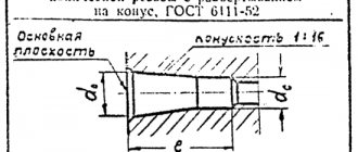
Taper
The ratio of the difference in diameters of two cross sections of a cone ( Dd.
) to the distance between them (
l
) (Fig. 6.39,
a
) is called
taper
(
K
)
: K =
(
D – d
)
/l.
Rice.
6.39. Constructing a taper and applying this value
For example, a conical element of a part with a larger base diameter of 25 mm, a smaller base diameter of 15 mm, and a length of 50 mm will have a taper K =
(
D – d
)
/l
= (25 – 15)/50 = 1/5 = 1:5.
GOST 21.502-2016 SPDS. Rules for the execution of working documentation for metal structures
This GOST establishes the composition and rules for the execution of working documentation for building metal structures, drawings of the KM brand, but does not apply to the execution of detail drawings of metal structures of the KMD brand.
General view drawings of metal structures
According to clause 6.2.2, the following dimensions are indicated on the general drawings:
Overall dimensions are given both for the entire structure as a whole (spans, length, width, height, diameter, etc.) and for its largest elements (height of trusses, etc.).
Characteristic are the dimensions that determine the shape of a building or structure and its individual parts: slopes (roofs, bottoms, road surfaces, etc.), radii of curved surfaces, dimensions that determine the change in the width of the towers along the height, etc.
Layout diagrams of elements of metal structures
In accordance with clause 6.3.1, Layout diagrams for elements of metal structures are carried out in accordance with subsection 6.3 “Layout diagrams for elements of prefabricated structures GOST 21.501-2011”, taking into account the specifics of making drawings of metal structures.
Drawings of elements of metal structures
According to clause 6.4.2, the dimensions of the elements of metal structures are indicated on the drawings:
6.4.4 The dimensions of welds and the number of fasteners are determined when developing detail drawings of the KMD grade.
Drawings of metal structures assemblies
In accordance with clause 6.5.4 The following dimensions are indicated on the assembly drawings:
Note - The thickness of parts, dimensions of welds, number, pitches and strength class of bolts or other fasteners are not indicated if they can be determined during the development of detail drawings of the KMD grade.
GOST 21.504-2016 SPDS. Rules for the execution of working documentation for wooden structures
This GOST establishes the composition, content and rules for preparing working documentation for wooden structures of buildings and structures for various purposes, including when using standard wooden structures.
Layout diagrams of structural elements
According to clause 6.2, the following dimensions are indicated on plans and sections of layout diagrams:
Assembly drawings of structures
In accordance with clause 7.2, the following dimensions are given on the assembly drawings of structures:
According to clause 7.4, the structural units show: sections of elements, shapes and sizes of inserts, dimensions, number and breakdown of connecting elements - wooden or metal plates, linings, nails, screws, bolts, screws, dowels, etc.
Drawings of structural components
According to clause 8.4, the following dimensions are indicated on the drawings of structural units:
Source