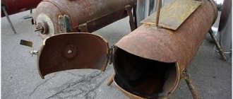
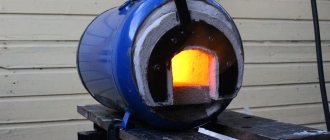
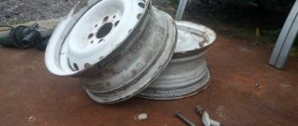
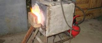
At home, homemade melting furnaces are most often used to melt aluminum. If you want to make such a stove for yourself, we would like to share with you the idea of the author of the YouTube channel Gianni Pirola Fai Da Te
.
To make a melting furnace, you will need a gas cylinder - preferably a propane one, since its metal wall thickness is 3 mm.
Please note: while most homemade smelting furnaces run on gas, this furnace option is attractive because it runs on coal. For some this may be an important characteristic.
Furnaces for aluminum: gas, fuel oil and diesel fuel
The following types of fossil fuels are used in furnaces for melting, aging and processing aluminum:
- natural gas;
- fuel oil;
- diesel fuel.
The choice of energy carrier depends on its availability at the production location. Natural gas is very convenient for use in furnaces, but it can be used if there is an accessible gas pipeline nearby. If this is not possible, then use fuel oil or diesel fuel.
Diesel fuel is more convenient than heating oil, but has a high price. Fuel oil is cheaper than diesel fuel, but its use is associated with certain difficulties.
How to build a smelter
To craft a smelter, you will need the following materials: 5 units of surtling cores and 20 units of stone. The smelter can be placed anywhere, but there must be a workbench nearby. It is better not to place the smelter indoors, as it takes up a lot of space. Once you have chosen a location, you can start building:
- Select the hammer in your inventory;
- Press F to switch to the Crafting panel;
- Press Q or E to switch to the smelter;
- Click the left mouse button to place the smelter on the selected location.
The smelter is ready to go.
Electric furnaces for melting metal
The basis of such a stove is asbestos, which can be replaced with tiles. Electrodes installed in a melting furnace with your own hands must have a voltage of 25 V.
They are made in the following order:
- They are machined from the brushes of an electric motor.
- 6 mm holes are drilled into the assembly.
- A wire with a cross section of 5 mm is passed through them.
- A nail is driven in to secure the wiring.
- In order to improve contact with graphite, the file makes notches.
Mica is placed inside the furnace as a heat insulator. When connecting to the network, you need to use a step-down transformer. After production, the oven turns on and runs for some time in idle mode.
Read also: DIY sword sheath
Graphite crucible
Graphite is a material that has many unique properties. Positive qualities of graphite:
To make a crucible from this material you will need:
Some of these materials can be used as independent units. For example, a graphite tube is essentially already a crucible; you just need to make a bottom in it.
The principle of manufacturing from all materials is the same. Let's look at the example of mortar. Two forms are made. You can roll it out of thick paper to make it easier to remove later. The outer shape has the configuration of a hollow cylinder , while the inner one is simply a cylinder. The small cylinder is inserted into the wider one. The mixture will be poured between them. The mold is placed in a plastic cup and mortar powder is poured into it. You need to fall asleep with a slide, as it will sit down when you need to compact it. 15 cubes of liquid glass are poured into this powder using a syringe. Everything is mixed and the consistency of shortcrust pastry is obtained. Stuff into the mold in small portions.
The result is something like a glass turned upside down. To prevent the form from sticking to the table, it is best to do the entire procedure on cellophane. Then the mold is turned upside down and the inner cylinder is removed. It is also best to initially glue it with cellophane or tape. Then, when removing, the shape of the crucible will not be damaged.
After the crucible has dried, it must be placed in the inductor and heated. This must be done at low temperatures , since all the water should evaporate, despite the fact that outwardly it seems as if it is not there at all. If the crucible is not preheated and you immediately start melting in it, it will most likely burst. After warming up, when you tap the crucible, it will make a ringing sound. This indicates that the crucible is well made.
By following the instructions presented, you can quite easily acquire a homemade melting furnace that will last no less than a purchased one. The main thing is to take your time, be careful in your work and not violate manufacturing technologies.
Source
Copper smelting
At home, you can use foam concrete material to melt copper. 2 cylinders with a diameter of 100 mm are cut from such material. The height of one is 100 mm, and the second is 15. Laying one on top of the other, a hole with a diameter of 15 mm is drilled in the middle. In the larger cylinder, in the middle, a funnel-shaped hole is made to a depth of 85 mm. In the middle of the cylinder, on the outside, a groove is cut and tied with wire. It is needed to ensure that the part does not fall apart due to temperature.
An adapter is placed on the gas stove. A larger cylinder is placed on top so that the conical funnel is directed upward. The top is covered with a small cylinder with a hole. When lighting the burner, lower a piece of copper rod into a small hole until it touches the wall of the funnel. After a minute the rod will melt.
Cupola
In foundry production the following are used:
– melting furnaces for producing molten metal;
– thermal furnaces for heating castings for the purpose of their subsequent heat treatment;
– dryer for drying casting molds.
In all these furnaces, the processes of converting some type of energy into heat and then transferring this heat to the material being melted, heated or dried take place.
In the foundry industry, cupola furnaces for smelting cast iron, three-phase AC electric arc furnaces for smelting steel and cast iron, steel from scrap metal and for overheating liquid cast iron produced in cupola furnaces or other primary melting furnaces, DC arc furnaces, induction crucible and channel furnaces are widely used. furnaces of industrial frequency and high frequency.
A cupola furnace is a shaft furnace designed for melting cast iron.
The metal cylindrical casing of the cupola is mounted on columns and lined with refractory bricks on the inside (Fig. 1). The supporting part (Fig. 2) absorbs the static load from the entire cupola and the dynamic load from the loaded charge and consists of a foundation slab 1
, four columns
2
, support frame
3
, bottom plate
4
, bottom
5
, mechanism
6
for opening and closing the bottom.
The cupola bottom consists of two lids (half-bottoms), which are suspended using axles on an axis passing through bearings 7
mounted on the bottom plate. The bottom slab serves to secure the lower columns and evenly distribute the load on the foundation.
To protect against hot melt residues pouring out of the cupola through the hinged bottom, the slab is deepened 150–200 mm from the floor level, which is covered with dry molding mixture.
| Rice. 1. General view of a cupola with an expanded combustion zone: 1 – foundation slab; 2 – column; 3 – support frame; 4 – hearth plate; 5 – bottom; 6 – mechanism for opening and closing the bottom; 7 – cupola furnace; 8 – tuyere; 9 – cupola shaft with water cooling of the shaft body; 10 – tuyere box; 11 – charge loading unit; 12 – metal receiver-slag separator for releasing metal and slag; 13 – device for cupola gas sampling and cleaning; 14 – chimney Rice. 2. Cupola support: 1 – foundation slab; 2 – columns; 3 – support frame; 4 – hearth plate; 5 – bottom; 6 – mechanism for opening and closing the bottom; 7 – cover rotation axis |
The cupola shaft consists of a cylindrical casing 1
(Fig. 3), made of sheet steel 6–12 mm thick. Inside the casing there is a refractory lining 2. Between the casing and the lining there is a gap of 25–30 mm, which is filled with refractory non-sintering material, for example, lean sand, to ensure unhindered expansion of the lining when heated.
| Rice. 3. Section of the cupola shaft |
The shaft is installed on the bottom plate 8
above the hole is closed with a hinged bottom
7
.
On the bottom, a pod, or flake, is filled 6
thin molding sand in a layer 200–300 mm thick.
The stuffing box has a slight slope towards the hole 4
, called the cast iron tap hole
4
.
5
adjoins it .
If the cupola is without a pit, then the cast iron taphole is sealed with clay mass during melting and is torn off only for the period of cast iron production. In a cupola furnace with a pit, the cast iron tap hole serves as a channel through which cast iron from the hearth continuously flows into the pit. Opposite the cast-iron tap hole 4
at the floor level, a working window
10
, which is used for filling the hearth, laying in firewood and igniting it, which is covered with refractory bricks during melting, clogged with molding mixture and closed with a door
9
.
To release slag, there is a slag tap hole, which is located 75–150 mm below the tuyeres. The shaft (Fig. 5) is divided in height into the lower part, from the hearth to the first row of tuyeres, called the forge, and from the first row of tuyeres to the threshold 11
filling window
12
– the shaft itself.
The cupola shaft has a cylindrical, channel or complex (domain) profile. The shaft body along the entire height or only in the lower part can be cooled with water. The water-cooled zone, with the exception of the hearth, as a rule, does not have a refractory lining. The area of the cylindrical cupola shaft that is not cooled by water has a refractory lining with a thickness of 180–350 mm. Due to the low cost of the lining, the duration of operation of the cupola zone not cooled by water before knocking out for routine repairs does not exceed two shifts.
Cupola with a small conical profile of the water-cooled housing shaft 9
(Fig. 1) with extended water-cooled copper lances
8
, thickened hearth lining
7
is designed for long-term operation without knocking out for special repairs of the lining. The upper part of the shaft, located below the filling window, is lined with cast-iron hollow bricks to prevent the destruction of the masonry from impacts of the loaded charge.
The tuyere device (Fig. 4) of the cupola consists of a box 4
throttle valves
5
to regulate the amount of air supplied to the tuyeres. The box is made of steel sheets 6–12 mm thick and welded to the cupola casing. Throttle valves are mounted in cast cylindrical casings, which are bolted to the bottom of the tuyere box.
Rice. 4. Diagram of supply of heated air to the cupola and selection of cupola gases (tuyere device): 1 – loading window; 2 – hole for gas sampling; 3 – pipes for water drainage; 4 – tuyere box; 5 – throttle valve
| Rice. 5. Siphon slag separator: 1 – channel for cast iron and slag; 2 – tuyere; 3 – pipe for water drainage; 4 – cover for inspection and repair; 5 – gutter; 6 – viewing window; 7 – gutter; 8 – control hole; 9 – siphon channel; 10 – hole for slag; 11 – slag |
Nozzles 2
tuyeres (Fig. 5) are cast iron, rectangular in cross-section, expanding inside the cupola. The nozzles are bolted to the cupola casing. In the tuyere box and tuyere elbows opposite the tuyeres there are inspection windows (peepers), through which you can observe the condition of the tuyeres.
The supply of heated air to the cupola significantly increases the temperature of the cast iron being smelted: the higher the air temperature, the higher the temperature of the metal. Hot air passing through the idle shell increases the temperature of the coke pieces, accelerates heating (blowing 500–550°C) and melting of the charge, and reduces coke consumption. The use of hot blast increases the productivity of cupola furnaces by up to 40% and has a positive effect on the metallurgical processes occurring in the cupola furnace: waste is reduced, coke consumption is reduced, and the consumption of blast furnace cast iron is reduced. To heat the blast, either cupola gases or additional fuel are used. Cupola gases are taken from the shaft through openings 2
(Fig. 4) located below the loading window
1
.
In modern cupola furnaces, water cooling of the melting belt and tuyeres is widely used. A ring tube 3
(Fig. 4) with holes for water drainage is attached to the cupola casing above the melting zone. Water washes the body and flows into a collecting ring gutter.
Metal and slag are drained from the cupola through a siphon slag separator (Fig. 5). The slag separator maintains excess pressure (equal to the pressure in the cupola), under which the cast iron and slag 11
come from the cupola through channel
1
to chute
5
.
Then the metal from the chute through the siphon channel 9
enters the chute
7
, and the slag
11
10
onto the chute
5
excess pressure .
This part of the slag trap has a hole with a plug for draining the remaining slag and cast iron 8
.
When the blast is heated due to the heat of the cupola gases, the air temperature reaches 600–650°C, which ensures the temperature of the combustion products entering the cupola is equal to 1750–1800°C in a reducing atmosphere.
Currently, closed-type cupola complexes with complete purification of exhaust gases, blast heating, and water-cooled melting belts, providing multi-week smelting operations, have become widely developed both here and abroad. Modern cupola complexes include equipment for collecting, weighing and loading the charge, an automated control system for the smelting process, devices for slag granulation, a recycling water supply system, hydraulic slag removal, a cooling and gas purification system, a recuperator, etc., ensuring reliable and economic operation of the cupola furnace.
Rice. 6. Cupola complex: 1 – trestle bunker; 2 – weighing trolley; 3 – installation for dosing coke; 4 – lift for charge; 5 – cupola; 6 – airlock chamber; 7 – dust settling chamber; 8 – ejector scrubber; 9 – afterburning chamber; 10 – radiation recuperator; 11 – slag separating chute; 12 – money box
Gas and coke ovens
The fuel for coke-gas cupola furnaces is coke and natural gas, which is burned in tunnels located along the perimeter of the cupola above the tuyeres. Gas burners are positioned in height so that the combustion products exit below the level of the idle shell of the cupola shaft by 250–300 mm. The conditions for metal overheating in a coke-gas cupola are approximately the same as in a coke cupola. The temperature of the cast iron on the chute is 1390–1400°C. The gas saturation of cast iron smelted in a coke-gas cupola furnace is slightly higher. When converting a coke cupola furnace to coke-gas heating, the consumption of coke per working shell decreases, which explains the tendency to switch to gas fuel.
In a coke-gas cupola, the composition of the gas atmosphere is more oxidizing than in a coke cupola, which increases the loss of silicon and manganese and worsens the conditions for carburization of the liquid metal.
The design of a modern coke-gas cupola furnace is shown in Fig. 7. The combustion products of gas and water vapor at a temperature of 1500–1550°C are supplied to the melting zone of the cupola shaft, an additional amount of heat is introduced, due to which heat exchange conditions are improved in two zones - the melting zone and the heating zone of pieces of solid charge, and in the overheating zone liquid cast iron, while maintaining the specific air flow, nothing changes. The heat from burning 25 m3 of gas per 1 ton of smelted cast iron makes it possible to reduce coke consumption by 25–35% and increase cupola productivity by 10% at a constant cast iron temperature.
Reducing coke consumption by burning cheap natural gas makes it possible to reduce the cost of cast iron, reduce its sulfur content, increase furnace productivity, reduce the influence of the quality of batch cutting, and simplify the regulation of the height of the idle pile by changing the gas flow rate in the burners. The latter distinguishes it favorably from a cupola furnace operating in oxygen-enriched air. However, coke-and-gas cupola furnaces also have significant disadvantages: the interaction of products that emit natural gas during combustion (CO2 and H2O) with deoxidized pieces of coke with the formation of 15–20% CO and 3–4% H2, which absorbs a large amount of heat); an increase in the temperature of the top gases by 100–150°C, causing additional heat losses; saturation of cast iron with hydrogen.
Rice. 7. Coke and gas cupola furnace: 1 – water collector; 2 – fireclay brick lining; 3 – rammed fireclay mass; 4 – water-cooled burner tunnel; 5 – gas burner; 6 – manifold for supplying natural gas; 7,8 – air collectors for burners and tuyeres, respectively; 9 – water cooling of the melting belt; 10 – water cooling of tuyeres and burner tunnels; 11 – copper water-cooled lance; 12 – stationary storage box; 13 – quick-change tap hole device; 14 – high-alumina refractories
If the combined consumption of coke and gas is estimated in units of equivalent fuel, it turns out that the consumption of coke-gas fuel will be higher, and the efficiency of the cupola furnace is lower than for a conventional coke furnace. Savings when operating a coke-gas cupola furnace are achieved only due to the low cost of natural gas, so even increased gas consumption compared to the saved coke provides a certain economic effect.
A gas cupola furnace is a shaft-type combustion furnace. It differs significantly from coke and coke-gas cupola furnaces. In a gas cupola furnace there is no traditional idle coke shell; it has a constant height of the melting zone above the gas burners and a limited overheating zone. Gas cupola furnaces are structurally differentiated into: a) cupola furnaces with ledges in the shaft (Fig. 8); b) cupola furnaces with a jumper in the shaft and c) cupola furnaces with an external overheating chamber. In the cupola shown in Fig. 8 two ledges are made along the height of the shaft 6
and
12
, preventing the entry of charge materials into the lower part of the gas combustion chamber
4
, the overheating zone.
Rice. 8. Gas cupola furnace: 1 – shaft; 2 and 4 – water cooling; 3 and 5 – shaft undercuts; 6 and 12 – ledges; 7 – storage box; 8 – bottom opening mechanism; 9 – pool for liquid cast iron; 10 – burners; 11 – gas combustion and cast iron overheating chamber; 13 – charge loading system
The upper part of the cupola shaft (above the ledges 6
and
12
) is intended for heating and melting the charge, and the lower one is for overheating liquid cast iron. Both the upper and lower ledges experience high thermal loads and are therefore cooled with water. Along the entire perimeter of the lower part of the gas combustion and superheating chamber, tunnels are built in one or two times - tubes in which gas burners are located.
Before melting, the superheating chamber is heated by gas burners to a temperature of 1600°C. Then, after reaching the required temperature and composition of the furnace atmosphere, the charge is loaded into the cupola shaft. The metal melts, flows into the cupola overheating chamber, from where it continuously flows into the storage tank.
The main advantages of gas cupola furnaces over coke furnaces are that they do not require the use of scarce coke, and there is a significant reduction in sulfur content (5–6 times lower than in cast iron smelted in coke cupola furnaces). At the same time, in gas cupola furnaces it is more difficult to obtain cast iron with a carbon content of more than 3–3.2%. This is explained by the absence of idle coke shells in the coke cupola and the formation of an oxidizing atmosphere in the overheating chamber, which contributes to the waste of chemical elements of cast iron (carbon, silicon, manganese). In such cases, high-carbon materials, for example, pieces of waste graphite electrodes, are artificially added to the charge.
Melting gold and silver
A gold smelting furnace is easy to make at home. It is also applicable for smelting silver.
Read also: Highlights on dark hair with gray hair
The operating procedure is as follows:
- A fireclay brick is taken and cut into 2 parts. Using a Pobedit drill with a diameter of 48 mm, a through hole is made in one half, in the middle. And in the second hole is drilled to half the height.
- A spiral is drawn through the hole and both halves are tightened with bolts, holes for which are drilled from the sides.
- A graphite crucible is installed on top.
- A metal frame is made and both halves are inserted into it.
- All side gaps are covered with clay.
- Voltage is applied to the removed ends of the spiral.
- Pieces of gold or silver are thrown into the crucible.
- During the heating process, the non-ferrous metal melts.
Making furnaces for melting metal with your own hands is a complex process, but doable. To do this, you need to study the characteristics of the types of equipment. Decide which one is most preferable to the given conditions. Manufacturing costs will quickly pay for themselves.
Security measures
When starting to operate a homemade furnace, you should take into account the threats that arise during smelting:
- Splashes of molten metal and heated parts of the installation often cause severe burns.
- In case of fire, there should be a bucket of cold water near the workplace.
- The lamp circuit must be placed in a housing to prevent accidental contact with parts that are supplied with high voltage.
- The range of the electromagnetic field is not limited by the dimensions of the housing. Therefore, before melting begins, you need to remove all metal jewelry and put electronic devices away. If you are near the oven, a mobile phone, digital camera, or MP3 player may be damaged. People with an implanted pacemaker are not recommended to be near the induction unit while melting is in progress.
In a home furnace, not only melting is performed, but also parts are heated before tinning, molding, and hardening. Despite the simplicity of the considered circuits, homemade induction installations are not inferior in basic characteristics to factory-made models for domestic use. If necessary, they can be easily configured to solve a specific problem by changing the parameters of the induction coil and the output signal of the generator.
Concept of temperature scale
Some non-metallic objects also have similar properties. The most common is water. A temperature scale was developed regarding the properties of the liquid that occupies a dominant position on Earth. The reference points are the temperature of changes in the aggregative states of water:
- Transformations from liquid to solid and vice versa are taken to be zero degrees.
- Boiling (vapor formation inside a liquid) at normal atmospheric pressure (760 mm Hg) is taken to be 100 ⁰C.
Attention! In addition to the Celsius scale, in practice temperature is measured in degrees Fahrenheit and on the absolute Kelvin scale. But when studying the properties of metal objects, other scales are used quite rarely.
