Elimination of welding defects
If during control tests a defect is found that is unacceptable for the safe operation of structures, then the inevitable process is the elimination of defects in welded joints.
To eliminate identified deficiencies, the following methods for eliminating weld defects are used:
- lack of fusion, foreign inclusions, small internal cracks are subject to mechanical cutting or complete cleaning, after which re-welding is carried out;
- elimination of large and deep cracks is carried out by welding after preliminary mechanical cleaning or drilling;
- welding in thin layers or surfacing is used to eliminate undercuts and incomplete seams;
- the deposits are destroyed mechanically using an abrasive tool;
- Heat treatment eliminates overheating of the metal.
These are the main methods for correcting defects in welded joints, which are used to eliminate defects. After the design is corrected, control tests are repeated and only if there are no defects, their further operation is allowed.
Control methods
All welded joints must undergo inspection. This is especially true for structures whose operation carries increased responsibility. Inspection using special equipment allows you to find out how serious flaws there are in welded joints. Most defects result in a decrease in density. The consequence may be an inability to withstand heavy loads.
To detect defects in welds and joints, various inspection methods are used:
- Visual inspection. It is mandatory for the initial identification of deviations from the norm. For a more accurate analysis, use a magnifying glass with high magnification.
- Flaw detection. The basis is the property of the material to change its color when interacting with various liquids, in particular kerosene. The advantages include the safety of the method and the speed of verification.
- Magnetic method. When passing magnetic waves encounter defects, they are distorted. Measuring distortions will allow you to judge the presence of defects.
- Ultrasound. Flaw detectors based on the use of ultrasonic waves measure their reflection.
- Radiation method. Welds are examined with X-rays. The resulting image is developed and decrypted. Special equipment is required. It can be stationary and mobile. The disadvantage is the possible impact on the health of the welder. Protection in the form of a special suit and mask is required.
All control methods used must belong to the group of non-destructive ones. Mechanical damage and destruction are not acceptable. It is permissible to use not one method, but a combination of them.
If a defect is detected, if possible, it must be corrected. The following methods are used for this:
- welding can remove large cracks;
- small cracks, uncooked areas and various foreign inclusions inside are subjected to complete stripping or cutting down;
- surfacing will eliminate incomplete seams and undercuts;
- sagging is removed with abrasive;
- heat treatment will eliminate the negative consequences of metal overheating.
These methods eliminate the almost inevitable occurrence of defects.
Classification of casting defects
In modern metallurgy, there are several classifications of casting defects.
Depending on the degree of change and the possibility of correction, types of defects are divided into:
- Conditional marriage. The casting has flaws that do not impair its performance. The casting goes into further processing
- A fixable marriage. The defects are significant, but can be corrected by one or another production method. For example, surfacing. After correcting the casting defect, the part also goes into further processing.
- The final marriage. It cannot be repaired because it is impracticable or very expensive.
Casting defects are also divided according to where they are found. Casting defects found inside the area are called internal.
Internal casting defect
If a defect is discovered during further processing, it is an external defect. Based on their external manifestations, the following main types of casting defects are distinguished:
Tides
This is an increase in the size of the castings that was not provided for in the project. Divided into
- Fills. - Arise along the line of joining of parts of the form. Arise due to non-compliance with the dimensions of the models and poor-quality connection of parts of the flasks
- Puffiness, or expansion, is obtained due to the pressure of the melt on the loose mixture.
- The build-up occurs due to the erosion of the mold by the melt flow during pouring.
- Notches (scallops, burrs) occur due to the melt getting into damage to the mold or core.
Surface defects
Defects during casting often manifest themselves in the form of surface imperfections. This includes
External casting defects
- Blockages. Masses of earth grains or slag. Caused by errors in the design of molds, ill-conceived placement of gates, non-compliance with the technology of storing and transporting flasks.
- Uzhimins occur during wet molding, when the layer of earth ruptures at the point of liquid condensation and melt flows into the resulting void.
- Adhesions, or non-stilines, appear in the contact zone of layers of cooled melt. Due to insufficient temperature, these flows cannot fuse properly.
- Films arise from the oxidation of alloying additives.
- Wrinkling, or folding, is the appearance of multidirectional folds on the surface due to the accumulation of significant volumes of carbon.
- The effusion appears as a large number of burst bubbles and is caused by the explosive release of graphite accumulations
- Kinglets are defects caused by melt splashing during pouring. The metal ball crystallizes and does not fuse with the casting.
- Warping of the casting occurs due to internal stresses due to uneven cooling
Cracks
Another common casting defect is cracks. They are:
Cracks - casting defect
- Hot. Occurs at the crystallization temperature due to shrinkage stresses. They take on an uneven appearance.
- Cold. They occur at lower temperatures and have a smooth, straight profile.
- Intercrystalline. Characteristic of alloy steels in areas of non-metallic inclusions.
Gas defects
- Sieve porosity is a lot of small bubbles in the body of a part.
- Gas shells are larger cavities that arise due to the release and association of small bubbles.
Burnt
Another type of defect is burnout. Features. The surface of the casting can be covered with slagged, melted molding earth (chemical burn-in) and unslagged facing earth with metal penetrating into its pores (mechanical burn-in).
Reasons for education. The low fire resistance of the molding mixture creates conditions for its chemical burning to the casting with the formation of low-melting compounds with oxides of iron, manganese, etc. Low-melting compounds penetrate deep into the molding soil due to capillarity. Such a burn is only difficult to remove with pneumatic chisels and emery stones.
The main causes of mechanical burns are the high porosity of the facing earth, as a result of which liquid metal penetrates into the ground, the high temperature of the metal when pouring the mold and the metal pressure (pressure) when pouring high castings.
Sand shells.
Sand cavities are closed or open cavities of irregular shape in various parts of the casting, filled partially or completely with molding material.
The formation of sand shells is caused by the following reasons:
1. Damage to the sand mold when removing the model from it or assembling the mold (applying the upper flask).
2. Destruction of parts of the mold by a jet of metal when filling the mold.
3. Erosion with metal of weakly packed areas of the mold or those burned in the dryer.
4. Mechanical clogging of the finished mold.
5. Incorrect molding slopes of the model.
6. Lack of fillets (rounded corners of the model) of the required size (as a result of which the earth crumbles from the corners).
7. Inconsistency between the dimensions and designs of the flask and the dimensions of the model (in a tight flask, a thin layer of earthen mold can crumble from the impact of a jet of liquid metal).
8. The use of faulty flasks causing damage to the mold.
9. Unsatisfactory quality of molding materials, destroyed in the mold by metal.
10. Uneven compaction in the molding sand form.
11. Insufficient strengthening of the form or its individual parts with frames, hooks, pins, etc.
12. Incorrect installation of rods.
13. Sharp blows, shocks in shape when turning over, assembling, moving.
14. Incorrect, inevitable installation of the weight, which is placed on the mold to prevent the metal from lifting the upper flask.
15. Incorrect direction of the metal stream and pouring the mold from a great height.
Cracks
Cracks can be through or non-through, so-called tears on the surface of castings.
Features. Hot cracks from internal stresses form while the metal has not yet cooled down, due to its increased shrinkage. Cold cracks are a rupture of metal at the end of cooling due to the manifestation of internal stresses caused by shrinkage. In hot cracks, which appear at high temperatures, the fracture surface is always oxidized, while in cold cracks, the surface is clean or sometimes covered with light tarnish.
Reasons for education. The reasons for the formation of cracks can be:
1. Incorrect design of the casting itself (sharp transitions in thickness, lack of fillets or inappropriate radius of their roundings).
2. Mechanical resistance from the mold, rods and frames that prevent free shrinkage.
3. Incorrect gating system (local overheating of the casting).
4. Incorrect dimensions and location of refrigerators, profits and vents.
5. Excessively high pouring temperature and harmful impurities in the metal.
Sometimes even a slight blow during knocking out of the flasks, during cutting, or during careless handling during transportation is enough for the casting to crack.
Preventive measures. To eliminate the possibility of cracks, it is necessary to minimize internal stresses in the casting. To do this, you need to apply the following measures.
1. Design castings so that they allow as free shrinkage as possible in all directions.
2. Strive to pour the metal into a wet form - one that is more pliable than a dry one.
3. The difference in the thicknesses of the mating walls should be minimal.
It is better to make a complex casting from several parts, which are then joined into one whole.
4. It is recommended to make the fillet radius from 1/6 to 1/3 of the thickness of the sections being connected. The fillet radius size should be chosen equal to 1; 2; 3; 5; 8; 10; 15; 20; 25; 30 and 40 mm.
5. If an uneven cross-section in a casting is unavoidable, it should be designed so that the massive and thin parts can shrink during shrinkage without interfering with each other (for example, springy curved spokes of flywheels and gears should be used instead of straight ones). By supplying metal to the thin or quartz parts of the casting, it is possible to equalize the cooling rate of their more massive and central parts.
6. Use metal refrigerators and refrigeration molding mixtures with increased thermal conductivity (chromium iron ore), which help prevent shrinkage defects. A mixture of chromium iron ore is used to cover those parts of the mold (internal corners, walls of massive parts) whose cooling needs to be accelerated. Refrigeration molding mixture is more convenient than metal refrigerators, since it is easy to give it any shape when lining models of the most complex configuration.
By changing the thickness of the mixture layer, you can regulate the cooling rate of different parts of the casting, both from the outside and from the inside.
7. To combat hot cracks from tensile forces during shrinkage between adjacent parts (for example, flanges, pipes, housings, steam valves, etc.), use a special highly pliable molding compound, and make the gating system so that the stream of hot metal does not gave excessive local overheating of the mold.
Voids
Voids are cavities and bubbles within the product.
If voids form, it is necessary to check the injection volume (stroke
screw
N).
If V
inr {H}
turns out to be insufficient, it should be increased.
You should also check the operation of the auger tip valve. When injecting material into the mold, there should be no leakage in the opposite direction (see section “Recommendations for organizing the plasticization process”).
The formation of voids is influenced by casting technological parameters.
To reduce voids, it is necessary to increase the supply of mold material during cooling to compensate for shrinkage. To do this, increase the casting pressure RL
or molding pressure
Рф,
if a molding mode with pressure relief is used (see section “Modes with pressure relief”), increase the holding time under pressure tvpd increase the temperature of the mold
Tf
.
The reduction of voids is facilitated by a decrease in thermal contraction of the material during cooling in the mold. To do this, reduce the material temperature T.
Increasing the inlet size improves the feeding of mold material during cooling and reduces voids.
Methods for correcting casting defects
To correct surface defects, mechanical processing is used - turning, milling or cleaning.
Milling processing of casting defects
If the dimensions of the part are reduced more than permissible, surfacing of a thin layer of metal is applied, bringing the dimensions to the required ones and, as a rule, improving the properties of the workpiece.
Ultrasonic non-destructive testing method
Internal defects are detected by non-destructive testing methods. Sometimes, if the cause of defect formation is internal stress, they can be removed by heating and cooling using a special technique. Unfortunately, more often than not, internal casting defects cannot be corrected.
If you find an error, please select a piece of text and press Ctrl+Enter.
Classification of defects in castings made of iron and steel
“Classification of defects in castings made of cast iron and steel”
According to GOST 15467-79, a defect is defined as each individual non-compliance of a product with established requirements. A product that has at least one defect is called defective. This means that at least one of the casting quality indicators exceeded the maximum permissible value.
Castings made by any method are controlled for quality; control is carried out by employees of the foundry, quality control department and, in some cases, representatives of the State Priemka Department.
Depending on the degree of defects, all castings are divided into four groups:
• suitable, fully meeting all established requirements of technical documentation and standards;
• conditionally suitable, having small deviations from the established requirements (minor defects) that do not have a significant impact on the performance of the casting or the product as a whole; castings are allowed for further processing and are used for their intended purpose with the permission of the main specialists of industrial enterprises after a thorough assessment of defects;
• correctable defects – castings that have one or more correctable defects, after correction of which they can be allowed for further processing and use for their intended purpose;
• irreparable or final defect – castings having such defects, the correction of which is technically impossible or economically impractical, or the quality of the correction cannot be controlled. Castings that have at least one fatal defect are subject to rejection.
The removability or irreparability of a defect is determined in relation to the specific conditions of production and repair.
Depending on the degree of defects, all castings are divided into four groups:
suitable, fully meeting all established requirements of technical documentation and standards;
conditionally suitable, having small deviations from the established requirements (minor defects) that do not have a significant impact on the performance of the casting or the product as a whole; castings are allowed for further processing and are used for their intended purpose with the permission of the main specialists of industrial enterprises after a thorough assessment of defects;
correctable defects - castings that have one or more correctable defects, after correction of which they can be allowed for further processing and use for their intended purpose;
irreparable or final defect - castings having such defects, the correction of which is technically impossible or economically impractical, or the quality of the correction of which cannot be controlled. Castings that have at least one fatal defect are subject to rejection.
The removability or irreparability of a defect is determined in relation to the specific conditions of production and repair.
Defects are divided according to different criteria. For example, depending on the predisposition of defects to detection, they can be obvious or hidden.
An obvious defect is one that is detected during an external inspection (visual inspection), or a defect for which the regulatory documentation provides appropriate tools and techniques for identifying it. Despite the impossibility of visual detection, such a defect is obvious, since if the prescribed flaw detection technique is used, it will certainly be detected.
A latent defect is a defect that is not detectable under the above conditions and is not detected by the equipment provided for control. Hidden defects are sometimes revealed during the machining of castings or during the operation of products, as well as during additional flaw detection by methods and means not provided for in the technological charts. It is most undesirable and dangerous when a hidden defect appears during the operation of the product, which can cause an emergency.
According to GOST 19200 - 80, defects in castings made of cast iron and steel are divided into five main groups (50 varieties). It should be noted that the adopted terminology is also widely used for castings from alloys based on aluminum, magnesium, titanium and others and therefore can be considered universal.
1. Geometric discrepancy (14 types):
Warp Rod warp Difference Rod fill Warping Non-fill Gap Break
What defects occur during welding work?
Depending on the causes of occurrence, size, shape and location on the seam, different types of defects are distinguished. To understand which methods of eliminating defects in welded joints will be the best, you first need to determine their type and why they occurred.
According to the classification according to GOST 30242-97, the following groups of defects are distinguished:
- cracks in welds, which can be transverse, longitudinal, radial and others;
- violation of the shape of the seam due to the formation of sagging, undercuts, burns, bulges, displacements and other flaws;
- the presence of pores, cavities, fistulas, and craters at the welding site. They can accumulate in one area or be distributed evenly throughout the entire seam;
- unwelded areas and unfused edges;
- the presence of solid (oxide, metal, slag) inclusions and inclusions in the weld.
Based on their location, defects are divided into internal, external and through. A specific digital designation by the classifier is set for all defects in welded joints, and methods for eliminating them are selected in accordance with the numbers marked in the places where they are present.
Three culprits for defects in anodized profiles
Three manufacturers take part in the production of anodized aluminum profiles:
- a foundry worker who produces the raw extrusion ingots;
- a pressing machine, which produces pressed aluminum profiles from these ingots;
- An anodizer who forms an anodic coating on these profiles.
When defects are discovered on finished anodized profiles, disputes often arise between the three manufacturers as to who is to blame for a particular defect. The issue is resolved more easily if all three performers are part of the same company. If they belong to different companies, then serious disagreements often arise about the causes of defects.
Due to the peculiarities of the formation of the anodic coating, the production of high-quality anodized profiles requires close and constructive cooperation between all three manufacturers:
The ingot manufacturer (caster) must ensure the uniformity of the chemical composition of the ingots and the uniformity of the cast structure. All this is achieved by the correct technology of casting ingots and their homogenization.
The profile manufacturer (presser) must ensure a uniform pressed structure of the profiles along their cross-section and length, the correct thermal technology (cooling on the press and aging), careful movement of the profiles along the press line and their careful transportation to the anodizing line.
The anodizer is responsible for the quality of storage and production movements of profiles intended for anodizing, the quality of mechanical and chemical surface preparation, the anodizing process itself and pore filling, as well as, if necessary, painting of the anodic coating of aluminum profiles.
In most cases, defects in an anodized surface cannot be detected until the product leaves the anodizing line. At this point, a lot of time, effort and money have already been spent on producing this defective product.
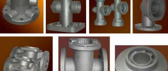
Casting defects
Defects in castings are conventionally divided into surface, internal, deviations in size and configuration, inconsistencies in the chemical composition, structure and mechanical properties of the metal.
Internal defects in castings
Internal casting defects include the following:
- blockages (open or closed cavities in the body of the casting, filled with shell mold material) - usually formed due to grains of sand entering the mold during molding into bulk filler, as well as the melt washing away “burrs” on the mold that form between the model and the gating system during careless soldering ;
- shrinkage cavities and porosity - arise due to insufficient nutrition of the casting during solidification, at excessively high temperatures of the melt and mold, due to violations of the chemical composition of the melt;
- gas cavities - are formed as a result of insufficient gas permeability of the shell shape and the formation of “air bags” due to improper design of the gating-feeding system;
- hot cracks are the result of a low-tech casting design (a combination of thin and massive walls, the presence of sharp corners, insufficient fillet sizes and transitions, etc.), as well as a high pouring temperature and insufficient mold compliance.
Deviations of the dimensions and configuration of the casting from the specified ones can be caused by various reasons. The main ones are the instability of the shrinkage of the model composition and the deformation of the shell shape during the calcination process, as well as the instability of the shrinkage of the casting metal. The accuracy of the dimensions and configuration of the casting is also influenced by the drying and calcination modes of the shell mold.
The instability of the shrinkage of pasty model compositions is largely influenced, for example, by the air contained in them. Air reduces the volumetric shrinkage of the model, but due to the variability of its content in different models in a batch, it causes significant instability in the dimensions of the models during shrinkage.
The deformation of the shell shape is most influenced by the polymorphic transformations of its material during heating and the resulting changes in the dimensions of the working cavity. Therefore, materials that do not have polymorphic transformations during heating and cooling and have a low thermal expansion coefficient (fused quartz, high-alumina fireclay, etc.) are promising for obtaining precise shapes and, accordingly, castings.
The discrepancy between the mechanical properties of a casting and the specified ones is usually caused by a discrepancy between the chemical composition and structure required, as well as the presence of shrinkage defects (cavities and porosity) in the casting, and an increased content of gases in the metal.
In addition to using known metallurgical means to eliminate these defects, attention should also be paid to the manufacturability of the casting design, the design of the gating-feeding system, which should provide power to the shrinkage of the casting, and to the relative position of the castings in the block and the castings relative to the elements of the gating-feeding system. If positioned incorrectly, individual parts of castings located close to one another can create a thermal knot, leading to delayed hardening of these parts and the formation of defects in them. If positioned incorrectly, individual parts of castings located close to one another can create a thermal knot, leading to delayed hardening of these parts and the formation of defects in them
If positioned incorrectly, individual parts of castings located close to one another can create a thermal knot, leading to delayed hardening of these parts and the formation of defects in them.
- ← Section 2.5
- Section 3.1 →
wavy surface
A “wavy” surface usually forms on a product if the mold is filled in two modes (see the section “Modes of filling the mold”).
The first mode (I) is a mode with a constant volumetric flow rate of material through the mold. It lasts from the moment filling begins until the highest (set) pressure in the hydraulic drive Pmax is reached. Filling the mold in this mode ensures a good external surface of the product.
If the set pressure in the hydraulic drive is not enough to fill the mold along the entire length in the first mode, the second mode of decreasing flow speed begins (II). When the material flows at a decreasing speed, small waves (traces of flow) become visible on the surface of the product, which create turbidity and a pockmarked surface. This worsens the appearance of the product.
If the appearance of the product is important, the mold must be filled in the first flow mode. To do this, you need to increase the material temperature Tl, increase the casting pressure Rl,
increase the volumetric injection rate Q and increase the temperature of the mold Tf.
The fluidity of the material can be increased and the mold can be filled in the first mode by adding modifying additives to the base material.
If possible, then to eliminate the defect in question, you need to switch to a lower-viscosity brand of polymer.
Plastic defects in metal products
When rejecting workpieces, quite often one has to deal with inclusions of foreign metallic or non-metallic bodies, and the latter come in different sizes and shapes.
A tear is a local non-through rupture located across or at an angle to the direction of processing of the material. Such defects are formed due to the disclosure of internal discontinuities in the material, as well as non-compliance with the standards established for the processing process.
A through gap differs from the previous type in that through discontinuities are observed on the metal product. They are formed when a flat workpiece with uneven thickness is deformed, or the cause of a through rupture can be rolled-in foreign bodies.
The puncture looks like non-through single or group point depressions. They appear when contaminated cutting fluids are used or small metal and foreign elements come into contact with the workpiece. Another reason for pinching can be protrusions and stuck particles on the rollers.
Recommended reading
- Cutting copper with a laser: advantages and disadvantages of technology
- Types of metal cutting: industrial applications
- Metalworking according to drawings: convenient and profitable
Dents are individual single depressions of various sizes, shapes, and having flat edges. Dents appear due to damage to the metal during production, transportation, and storage.
A nick is an irregularly shaped depression. Typically, such a defect has sharp edges, as it appears when a metal product is hit.
Imprint – periodically repeating depressions, protrusions located throughout the metal product or in some of its areas. Imprints appear under the influence of irregularities on the rolling and straightening rolls.
The seizure looks like a wide longitudinal depression with an uneven bottom and edges. The reason for its appearance is the sharp friction of the workpiece against the part of the equipment with which processing is carried out.
A notch is a longitudinal narrow depression, the bottom of which can be rounded or flat. Formed when a metal product blank is scratched by protrusions on the surface of the equipment.
A scratch is an irregularly shaped depression with a random direction. Appears due to mechanical damage, for example, during storage or transportation of metal products.
Abrasion is a loss of shine on a particular area of a metal product, as well as an accumulation of small multidirectional scratches. Such defects appear due to friction between metal products.
Adhesion occurs as a result of particles or a layer of metal from a tool sticking to a metal product.
Sunset is formed due to the pressing into the product of particles of the metal being processed, burrs, protrusions and other defects that appear during the processing process.
Burnout manifests itself in the form of dark, melted or oxidized spots on a metal product, which are formed if the temperature and heating time of the material have been exceeded.
Slag sinks.
Slag shells are irregular in shape and
rough surface. The shell cavity can be filled with slag completely or partially.
The sizes, number and location of slag shells are varied and depend on the reasons that caused their formation.
The main reason for the formation of slag cavities is the entry of slag into the mold along with the metal during pouring due to:
1. Poor cleaning of metal from slag.
2. Insufficient filling of the sprue bowl during pouring.
3. Incorrect gating system.
4. Insufficient fluidity of the metal.
5. Interruption of the metal stream during pouring.
Preventive measures. To combat slag shells it is necessary
provide an increased temperature when melting the metal in order to increase its fluidity and reduce viscosity. And also to improve the conditions for the floating of slag when keeping the metal in a ladle or pit before pouring. Slag must be removed from the metal surface using scrapers. To facilitate removal, liquid slag should be sprinkled with clean, dry sand, which makes it thicker.
To prevent slag from getting into the mold, it is necessary to take measures to retain it not only in the ladle, but also in the gating system. In the gating system, the slag is retained by slag catchers, in which it is separated from the metal due to the difference in specific gravity. The simplest slag catcher of a gating system is the gating bowl itself. It is necessary to correctly select the dimensions of the slag catcher and the sections of individual elements of the gating system.
When choosing a gating system, you should be guided by GOST and departmental or factory standards. Even with a properly constructed gating system, slag can penetrate into the mold if the gating system is not filled with metal throughout the pour or if the flow is interrupted.
Steel casting defects
Types of casting defects
Castings, like ingots, have their own defects (Fig. 48). In addition, in practice there are other defects: tides or local thickening of castings (flooding, swelling, build-up, collapse, undermining, crimping, scuffing; see Fig. 48); distortion of shape and size (underfilling, warping, different thicknesses, skew, breakage); discrepancy between the composition, structure and properties of alloys.
Rice. 48. Types of defects in castings: a - squeezing; b - sink and closed shrinkage cavity; c - kinglet; d - thermal crack; 0—form crimping; e - badass
The main ones are surface and internal defects.
Surface defects include:
burn-in, when the surface of the casting is completely or partially covered with a layer of molding material impregnated with metal and its oxides. The reason for this may be a high pouring temperature, a long pouring time, insufficient deoxidation of the metal, weak or, conversely, too strong compaction of the molding sand, low thermal conductivity of the mixture or its low gas permeability, unsatisfactory quality of cleaning of castings.
Uzhimina is a small thickening on the surface of the casting containing an intermediate layer of molding material. The reason for its formation is too slow pouring of the mold, unsatisfactory properties of the molding mixture (low strength, high thermal stresses), the presence of large flat surfaces in the castings, technological violations when pouring metal (uneven supply of metal, interruptions in the stream), increased gas content of the mixture, long-term standing of dry or dried molds before pouring, peeling of molding paint during pouring or drying, high gas pressure in the thickness of the mold.
A weld is a non-monolithic fusion of metal flows, having the appearance of a seam with rounded edges, extending into the depths of the casting. The reason for its formation is lack of welding of the metal at the confluence of two flows, low pouring temperature, slow filling of the mold, low fluidity of the metal (high-alloy steel, alloy), pouring with a thin or intermittent stream, etc.
A hot crack is a clearly visible rupture in the walls of the casting, passing along the boundaries of the metal grains, with an uneven black fracture surface and with traces of dendrites. It is formed in the presence of significant temperature differences in the walls and individual parts of the casting during the period of solidification and further cooling, with mechanical inhibition of shrinkage by elements of the gating system, with an elevated pouring temperature, uneven supply of metal to the casting, insufficient nutrition of massive casting units, with an increased content of impurities, increasing the fragility of the metal (for example, sulfur).
A cold crack is a weakly visible rupture in the walls of a casting with a light grainy fracture surface or tarnished color. The reasons for its formation are basically the same as for a hot crack, only their influence manifests itself at lower temperatures.
Silver stripes
When hygroscopic polymers flow, if they are not well dried, there are moisture bubbles on the surface of the flow front or near its inner surface.
After the moisture bubbles have reached the flow front, they begin to move along with the front perpendicular to the main flow and reach the walls of the mold (see section “Material flow along the mold”). On the wall of the mold, moisture bubbles are flattened and stretched in the direction of the material flow. On the surface of the product, characteristic shines from moisture are formed - silvery stripes.
To eliminate silver streaks on the surface of products, the material must be thoroughly dried before processing to reduce moisture in it.
The reduction of “silver” on the surface of products is facilitated by a decrease in the material temperature T
and reduced Form Q completion rates.