Technical characteristics of the cross-planing machine 7303
| Parameter name | 7303 | 7305 | 7307G |
| Basic machine parameters | |||
| Machine accuracy class | N | N | N |
| Slider stroke length, mm | 15..320 | 20..510 | 20..720 |
| Largest cutter cross-section (width x height), mm | 16 x 25 | 20 x 32 | 40 x 25 |
| The greatest distance from the supporting surface of the cutter to the bed (overhang), mm | 400 | 510 | 720 |
| Height of the slider above the working surface of the table, mm | 70..300 | 90..400 | 90..480 |
| Table | |||
| Dimensions of the working surface of the table - top, mm | 280 x 320 | 360 x 500 | 450 x 710 |
| Dimensions of the working surface of the table - left, right, mm | 280 x 320 | ||
| Maximum movement of the table by hand – horizontal, mm | 360 | 580 | 710 |
| Maximum movement of the table by hand – vertical, mm | 230 | 310 | 380 |
| Number of horizontal table feeds | 16 | 25 | 25 |
| Fast, horizontal movement of the table, m/min | – | 4,0 | 4,0 |
| Horizontal table feeds, mm/double stroke (number of steps) | 0,1..1,6 (16) | 0,2..5,0 (25) | 0,2..5,0 (25) |
| Dial division price, mm | 0,1 | 0,1 | |
| Caliper | |||
| Maximum vertical movement of the cutter head by hand, mm | 170 | 170 | |
| Dial division price, mm | 0,05 | 0,05 | 0,05 |
| Maximum angle of rotation of the cutting head to the entrance to the bed, degrees | ±60 | ±60 | ±60 |
| Maximum angle of rotation of the tool holder board, degrees | ±15 | ±15 | ±15 |
| Maximum displacement of the slider, mm | 270 | 310 | 410 |
| Maximum permissible cutting force, N | 11000 | 17650 | 19600 |
| Number of speed stages of the main drive (slider movement) | 4 | 8 | 8 |
| Number of double strokes of the slider per minute (number of steps) | 23, 47, 94, 186 (4) | 13,2..150 (8) | 10,6..118 (8) |
| Number of caliper feeds | – | 6 | 6 |
| Caliper feed, mm/double stroke | – | 0,166..1 | 0,166..1 |
| Electrical equipment. Drive unit | |||
| Number of electric motors on the machine | 1 | 1 | 1 |
| Table drive electric motor, kW (rpm) | 1,9..3,0 (710..3,0) | 5,5 | 5,5 |
| Dimensions and weight of the machine | |||
| Machine dimensions (length width height), mm | 1650 x 870 x 1540 | 2310 x 1055 x 1550 | 2790 x 1235 x 1665 |
| Machine weight, kg | 970 | 1930 | 2700 |
Bibliography:
Yakovtsev A.D.
Work on planing and slotting machines, 1966 Kopylov R.B. Working on planing and slotting machines, 1975
Petrukha P.G. Cutting of structural materials, cutting tools and machines, 1974
Related Links
Home About the company News Articles Price list Contacts Reference information Download passport Interesting video KPO woodworking machines Manufacturers
Technical characteristics of the cross-planing machine 7D36
| Parameter name | 7D36 | 7307d | 7D37 | 7310d |
| Basic machine parameters | ||||
| Machine accuracy class | N | N | N | N |
| Slider stroke length, mm | 150..710 | 150..710 | 150..1000 | 150..1000 |
| Largest cutter section, mm | 25 x 40 | 25 x 40 | 25 x 40 | 25 x 40 |
| The greatest distance from the supporting surface of the cutter to the bed (overhang), mm | 820 | 825 | 1120 | 1120 |
| Height of the slider above the working surface of the table, mm | 400 | 450 | 500 | 500 |
| Table | ||||
| Dimensions of the working surface of the table - top, mm | 450 x 710 | 450 x 710 | 560 x 1000 | 560 x 1000 |
| Dimensions of the working surface of the table - right, mm | 500 x 710 | 500 x 710 | 500 x 1000 | 500 x 1000 |
| Dimensions of the working surface of the table - left, mm | 500 x 710 | 500 x 710 | 500 x 1000 | 500 x 1000 |
| Maximum table movement – horizontal, mm | 700 | 710 | 800 | 800 |
| Maximum table movement – vertical, mm | 320 | 345 | 320 | 420 |
| Number of horizontal table feeds | ||||
| Limits of horizontal table feeds, mm/double stroke | 0,2..5,0 | 0,2..5,0 | 0,2..5,0 | 0,2..5,0 |
| Fast, horizontal movement of the table, m/min | 2,3 | 2,3 | 2,3 | 2,3 |
| Fast vertical movement of the table, m/min | 0,16 | 0,16 | 0,16 | 0,16 |
| Horizontal movement dial division price, mm | 0,1 | 0,1 | 0,1 | 0,1 |
| Horizontal movement of the table per one revolution of the handle, mm | 8 | 8 | 8 | 8 |
| Dividing price of the vertical movement dial, mm | 0,05 | 0,05 | 0,05 | 0,05 |
| Vertical movement of the table per one revolution of the handle, mm | 0,55 | 0,55 | 0,55 | 0,55 |
| Crawler. Caliper | ||||
| Maximum vertical movement of the caliper slide (cutter head) by hand, mm | 200 | 200 | 200 | 200 |
| Dial division price, mm | 0,05 | 0,05 | 0,05 | 0,05 |
| Movement of the caliper slide (cutter head) per revolution of the handle, mm | 5 | 5 | 5 | 5 |
| Tool holder window dimensions, mm | 32 x 55 | 32 x 55 | 32 x 55 | 32 x 55 |
| Maximum angle of rotation of the cutting head to the entrance to the bed, degrees | ±60° | ±60° | ±60° | ±60° |
| Maximum angle of rotation of the tool holder board, degrees | ±15° | ±15° | ±15° | ±15° |
| Maximum permissible cutting force, kN (tf) | 28 (2,8) | 28 (2,8) | 28 (2,8) | 28 (2,8) |
| Slider speed under load, m/min | 3..48 | 3..48 | 3..48 | 3..48 |
| Slider speed during return stroke, m/min | 16..48 | 16..48 | 16..48 | 16..48 |
| Caliper feed, mm/double stroke | 0,15..1,05 | 0,15..1,05 | 0,15..1,05 | 0,15..1,05 |
| Mechanical feed of the cutting head down | There is | There is | There is | There is |
| Lifting the cutting head during reverse stroke | There is | There is | There is | There is |
| Electrical equipment. Drive unit | ||||
| Number of electric motors on the machine | 2 | 2 | 2 | 2 |
| Main motion electric motor, kW (rpm) | 7,5 (970) | 7,5 (970) | 10 (970) | 10 (970) |
| Electric motor for rapid table movements, kW (rpm) | 1,1 (1400) | 1,1 (1400) | 1,1 (1400) | 1,1 (1400) |
| Dimensions and weight of the machine | ||||
| Machine dimensions (length width height), mm | 2850 x 1680 x 1840 | 2850 x 1645 x 1890 | 3700 x 1850 x 1980 | 3700 x 1835 x 1920 |
| Machine weight, kg | 3400 | 3400 | 4500 | 4400 |
Bibliography:
Kopylov R.B. Working on planing and slotting machines, 1975
Petrukha P.G. Cutting of structural materials, cutting tools and machines, 1974
Yakovtsev A.D. Working on planing and slotting machines, 1966
Related Links
Home About the company News Articles Price list Contacts Reference information Download passport Interesting video KPO woodworking machines Manufacturers
Electrical equipment, light, lighting
Many people prefer to do small carpentry work at home or in the countryside. This allows you to give free rein to your imagination and save money from the family budget. But to work with wood, you need available tools, for example, a planer, which you can make yourself.
The emergence of the planer
The first planing machine has been known since the time of Leonardo Da Vinci. But it did not influence the development of this equipment, since all records were lost. The scientist de la Hire from France in 1719 designed a planing machine, which was originally a modification of a lathe, and the movement was carried out by a rope from the beam.
And today there are many different planing machines, which, depending on the work performed, are divided into the following groups: general purpose machines, specialized and special machines.
General purpose machines include longitudinal planing and cross planing. Special machines are designed to perform specific detailed operations and are mainly used in mass production.
Specialized machines include cross-planing machines with a movable carriage for working with heavy parts, pit longitudinal planing machines for processing heavy and large parts, and edge-planing equipment for processing the edges of large sheets.
The longitudinal planing machine is designed for processing large workpieces. Such devices come in single- and double-column types. In the process of cutting metal on a longitudinal planing machine, movements are transferred to the workpiece, which is previously fixed on the table of the planing machine. Its main characteristics are the width and length of the planing. The maximum length reaches up to 25, and the width reaches 5 meters.
A cross-planing machine is used to work with medium or small workpieces. The movements are transmitted to the cutting tool, and not to the workpiece. This tool is placed on a slide. A characteristic of such a planing machine is the stroke length of the slide, which reaches 2.5 meters. You can move the table where the workpiece is fixed in horizontal and vertical planes.
Purpose of planing machines
Planing machines are necessary for processing ruled surfaces - vertical, horizontal and inclined planes. Ruled surfaces also include shaped surfaces, which are a combination of planes located at different angles.
With the help of metalworking and woodworking planing machines, it is also possible to process shaped surfaces, the profile of which has curved sections that are formed by circular arcs or complex curves. Planing machines process not only flat surfaces, but also grooves, straight grooves, ledges and various recesses. It is possible to process metal in a closed loop.
Small-sized parts and large forgings, welded structures and castings that have a length of up to 12 meters, a width of up to 6 meters and a height of up to 3 meters are processed using a planing machine. The weight of such parts can reach up to 200 tons.
On planing machines, the workpiece is processed along a plane, thickness or angle, thanks to which the lumber acquires ideal evenness. On a double-sided jointing machine, the layer and the edge of the part are simultaneously processed. Parallel planes are processed using double-sided thicknessing equipment.
Metal-cutting machines of a planing nature are used in special machine shops for processing all kinds of parts in the automotive industry. They are also found in many repair shops and tool shops. They are well suited for working with parts made of steel, various non-ferrous alloys and even some types of plastic.
Wood planing machines are used to process the surface of wood after sawing “clean”, making lumber and parquet. They are designed for processing straight workpieces and plane milling. Using different sets of knives allows you to work with soft (spruce, pine) and hard (poplar, oak, beech) wood species.
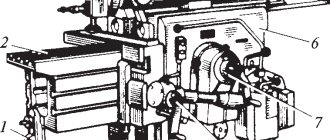
Brief description of the design and operation of the machine
bed
The machine bed is a solid box-shaped body mounted on a foundation plate. The strength and rigidity of the frame is achieved by the presence of internal ribs in it. The upper part of the frame has prismatic guides for the slide. The front vertical wall of the frame has guides for the vertical table slide. To mount the electric motor, rocker mechanism and other parts of the machine, flanges and plates are provided on the frame.
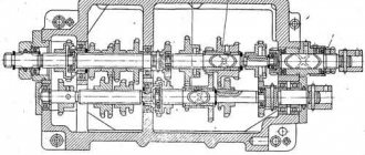
Gearbox
The gearbox is mounted inside a hollow frame and consists of three parallel rollers with movable gear blocks.
Crawler (Dolbyak)
The slider is a hollow steel body that is located on the upper guides of the frame and performs reciprocating movements along them. The slider receives movement from the swinging slide. The stroke length adjustment mechanism is located inside the slide.
In the front part of the slide there is a support with a tool holder (cutting head), which can be installed at an angle of 60 in the vertical plane. The caliper is moved up and down by hand using a lead screw.
Rocker mechanism
The rocker mechanism consists of the following parts:
- The slide has a U-shaped cross-section, hinged at the top with the slider using a cam;
- A rocker gear mounted on a hollow roller rotating in a cast iron cabinet;
- A horizontal table feed mechanism with a crank mounted on the other end of the hollow roller;
- A mechanism for setting the stroke length of the slider, consisting of a roller with a square, a conical pair, a screw and a rocker pin.
To determine and set the stroke length of the slider, there is a scale on the frame with divisions from 0 to 650 mm.
The rocker gear is driven by the drive gear of the gearbox mechanism.
Table
The table assembly consists of the following parts:
- Box-shaped table;
- Vertical slide or traverse;
- Horizontal or cross slide.
The table has horizontal and vertical movement.
- Horizontal movement of the table is carried out mechanically and by hand. Mechanical movements - using a ratchet mechanism, a lead screw and a nut.
- Vertical movement of the table is carried out only by hand using a telescopic screw, a conical pair, a roller with a square and a crank handle.
Machine drive
The machine drive consists of a 3.3 kW flanged electric motor, from which the movement is transmitted to the gearbox using a worm gear.
The machine is lubricated manually.
Electrical equipment, light, lighting
Many people prefer to do small carpentry work at home or in the countryside. This allows you to give free rein to your imagination and save money from the family budget. But to work with wood, you need available tools, for example, a planer, which you can make yourself.
The emergence of the planer
The first planing machine has been known since the time of Leonardo Da Vinci. But it did not influence the development of this equipment, since all records were lost. The scientist de la Hire from France in 1719 designed a planing machine, which was originally a modification of a lathe, and the movement was carried out by a rope from the beam.
And today there are many different planing machines, which, depending on the work performed, are divided into the following groups: general purpose machines, specialized and special machines.
General purpose machines include longitudinal planing and cross planing. Special machines are designed to perform specific detailed operations and are mainly used in mass production.
Specialized machines include cross-planing machines with a movable carriage for working with heavy parts, pit longitudinal planing machines for processing heavy and large parts, and edge-planing equipment for processing the edges of large sheets.
The longitudinal planing machine is designed for processing large workpieces. Such devices come in single- and double-column types. In the process of cutting metal on a longitudinal planing machine, movements are transferred to the workpiece, which is previously fixed on the table of the planing machine. Its main characteristics are the width and length of the planing. The maximum length reaches up to 25, and the width reaches 5 meters.
A cross-planing machine is used to work with medium or small workpieces. The movements are transmitted to the cutting tool, and not to the workpiece. This tool is placed on a slide. A characteristic of such a planing machine is the stroke length of the slide, which reaches 2.5 meters. You can move the table where the workpiece is fixed in horizontal and vertical planes.
Purpose of planing machines
Planing machines are necessary for processing ruled surfaces - vertical, horizontal and inclined planes. Ruled surfaces also include shaped surfaces, which are a combination of planes located at different angles.
With the help of metalworking and woodworking planing machines, it is also possible to process shaped surfaces, the profile of which has curved sections that are formed by circular arcs or complex curves. Planing machines process not only flat surfaces, but also grooves, straight grooves, ledges and various recesses. It is possible to process metal in a closed loop.
Small-sized parts and large forgings, welded structures and castings that have a length of up to 12 meters, a width of up to 6 meters and a height of up to 3 meters are processed using a planing machine. The weight of such parts can reach up to 200 tons.
On planing machines, the workpiece is processed along a plane, thickness or angle, thanks to which the lumber acquires ideal evenness. On a double-sided jointing machine, the layer and the edge of the part are simultaneously processed. Parallel planes are processed using double-sided thicknessing equipment.
Metal-cutting machines of a planing nature are used in special machine shops for processing all kinds of parts in the automotive industry. They are also found in many repair shops and tool shops. They are well suited for working with parts made of steel, various non-ferrous alloys and even some types of plastic.
Wood planing machines are used to process the surface of wood after sawing “clean”, making lumber and parquet. They are designed for processing straight workpieces and plane milling. Using different sets of knives allows you to work with soft (spruce, pine) and hard (poplar, oak, beech) wood species.
Cutters of metalworking machines
A cutter is the main tool used in processing metal surfaces. The cutter is indispensable for turning, planing and slotting work.
Modern installations can be equipped with several cutters, which significantly speeds up the work process and affects the final quality of the product. The more cutters installed on the machine, the better for the future product.
Machine models differ in the possibility of multiple installation of cutters. Therefore, installations are divided into:
- one-sided;
- double sided;
- four-sided.
Geometric parameters of a planing cutter
The tool used directly affects the quality of cutting and the future product. Incisors differ radically in their properties. The material of the cutting base of the cutter (head) is especially important. No less important are the dimensions of the cutter shaft, as well as its shape. The tool is distinguished by type and the one that is needed for a particular job is chosen.
There are several such types:
- trimming;
- checkpoint;
- shaped;
- cutting;
- finishing
Planing cutters
Description of the kinematic chains of the 7B35 machine
Main movement chain
The movement from the electric motor is transmitted through a V-belt transmission to the drive pulley of the machine.
Drive pulley speed:
When the disc friction clutch is turned on, rotation from the drive pulley is transmitted to the second shaft of the gearbox with two blocks of gears 1-2 and 3-4, by switching which four speed stages are transmitted to the third shaft of the gearbox. Gear 9 with an elongated tooth, wedged on the third shaft of the gearbox, is in constant engagement with wheel 10 of the movable block of gears 10-11, meshing with one of the pair of rocker wheels 21-22. By switching the block of gears 10-11, the previously obtained number of speeds is doubled.
The rocker mechanism converts the rotational motion received from the gearbox into a linear reciprocating motion of the slider. In this case, the swinging link imparts an uneven speed to the slider. The highest speed of the working stroke of the slider is achieved at the middle position of the slide, the lowest - at its extreme positions.
The idling speed of the slider is significantly higher than that of the working one, which saves time spent on unproductive idling movements of the machine.
Table feed chain
A cam mounted on the shaft of the rocker mechanism rotates the gear sector 30, which engages with the gear 31; the latter, through the leash and the pawl sitting on it, turns the ratchet wheel 32, connected by a cam clutch to the shaft of the conical wheel 33. The conical wheel 33 engages with the wheel 34, from which the movement is transmitted through the shaft to the conical wheel 37. By engaging the cam clutch with one of the conical wheels 38 or 39 communicates rotation to the lead screw 40 and reversal of the table movement.
The amount of table feed depends on the angle of rotation of the ratchet wheel, i.e. on the number of teeth captured by the dog.
Caliper feed chain
During the reverse (idle) stroke of the slider, the feed mechanism lever, falling on a special cam mounted on the upper plane of the frame, turns the ratchet wheel 45, connected by means of a pin and pawl to the conical wheel 46. Then the movement is transmitted to the conical wheels 47, 48, 49.
The conical wheel 49 serves as a nut 55 for the caliper feed screw.
Mechanism for setting the extension of the slider
By rotating the crank handle, placed on the square end of the gear shaft 51, as well as through the bevel wheel 52, screw and nut, the slider is moved relative to the workpiece. This sets the overhang of the slider.
Mechanism for vertical movement of the table
Vertical movement of the table is carried out by hand rotation using the crank handle of the roller with a conical wheel 42; the roller transmits movement to the conical wheel 43, which serves as a nut for a fixed screw.
Mechanism for setting the stroke length of the slider
The stroke length of the slider is adjusted within 20±500 mm and is changed by shifting the rocker pin relative to the center of rotation of the rocker mechanism shaft. To do this, turn the roller with gear 23 and gears 24,25,26 with a crank handle, acting on screw 27 and nut.
Mechanism for fast (accelerated) movement of the table
The drive pulley of the machine, connected to a helical wheel 12, which is in mesh with the wheel 13, transmits movement to the sponge wheels 14-15 of the oil pump. A sprocket 16 is installed on the gear shaft 13, connected by a chain to a sprocket 17, sitting on the same shaft with a sprocket 18, connected by a chain to the sprocket 19 of the next roller. On the sprocket shaft 19 there is a gear 20 mounted, which engages with the wheel 29; the latter, when the cam clutch is turned on, imparts rapid movement to the table through conical wheels 33,34,37,38 (or 39) and a screw pair 40 and 41.
The table rapid movement chain includes links: 12, 13, 16, 17, 18, 19, 20, 29, 33, 84, 37, 38 (or 39), screw 40 and nut 41.
Kinematic diagram of the cross-planing machine 7E35
Kinematic diagram of the cross-planing machine 7e35
The kinematics of the machine consists of the following circuits. Asynchronous electric motor M (Fig. 151) serves for all mechanical movements of machine components. The main movement drive connects the engine with the slider and contains a gearbox (shafts I, II and III) and a crank mechanism KK.
Three double movable gear units provide eight speed levels. Disc friction clutch M allows you to connect a pulley Ø 335 and shaft I to stop the movement of the working parts without turning off the engine. Brake 77 is interlocked with clutch M and speeds up stopping.
The crank mechanism converts the rotational movement of the gear 102 together with the pin into a reciprocating rocking motion of the rocker. The upper end of the drawstring is connected by an earring with a slider. The pin is connected to a nut, which is moved by the square P2 of shaft I during adjustment. Moving the nut away from the shaft axis increases the radius of the crank, and therefore the swing angle of the rocker and the stroke of the slider. The travel location (initial position) of the slider is shifted by turning the handle screw P1 or P6.
7B35 cross-planing machine
Rom22 (26 June 2013 – 17:41) wrote:
Tell me, who knows what kind of magnet (type).
ExproSE (03 July 2013 – 17:11) wrote:
Post edited by kvasek: 31 March 2016 – 12:11
Post edited by Ricky: 31 March 2016 – 12:12
Post edited by Ricky: 31 March 2016 – 12:26
ExproSE, I strongly advise against placing the machine on vibration supports because large masses are in dynamics. (I tried it myself) At first everything was not bad, but when the speed increased (even to average values), the machine went on a journey around the workshop.
Rikki, your Mozhaisk machine was hanging in the market for a long time, unfortunately I never got around to getting to you and operating it live. Based on the photos, it is quite possible to restore it.
I also became the owner of this machine and am also interested in the drawing of the wedge that is responsible for feeding the caliper
ag-set (10 May 2013 – 00:57) wrote:
The bourgeois twin from which I think the 7B35 was ripped off
cog&shpuntik (December 31, 2016 – 21:30) wrote:
Keep the table from being torn off only by the screw for vertical movement of the table
umis (23 May 2013 – 21:13) wrote:
The Polish chuck makes clamping almost any tool wonderfully easy.
Passport for cross-planing machine 7B35
Documentation printing: — Year of documentation printing: — Number of folders: 2 Number of pages, sheets: 81
Find out the cost of documentation
The passport and documentation for this machine model are in our archive, in electronic form. The documentation set includes, in sections, according to the contents: 1. Manual for the machine Contents: 1. Purpose and scope of application of the machine 2. Unpacking and transportation of the machine Instructions for unpacking and transportation 3. Foundation of the machine, installation, installation, instructions for installing the machine 4 Preparing the machine for initial start-up 5. Machine passport Specification of the main groups of the machine Specification of control handles Specification of gears and worm wheels, worms and chain sprockets, nuts and screws 6. Description of the machine General layout and features of the machine Specification of the features of individual components 7. Electrical equipment of the machine Description of the electrical circuit of the machine Instructions for the operation and maintenance of the electrical equipment of the machine Specification of electrical equipment 8. Lubrication of the machine Specification for the lubrication scheme Instructions for servicing the lubrication system of the machine 9. Initial start-up of the machine 10. Setting up, setting up the machine and operating mode 11. Adjusting the machine Specification of spare parts Drawings of spare parts
2. Album of drawings, diagrams - Layout of rolling bearings - General view of the machine - Kinematic diagram of the machine - General view of the frame - Gearbox - Slider and support - Mechanism for vertical feed of support - Rocker mechanism - Table feed mechanism - Table - Electrical installation diagram of the machine - Schematic electrical diagram of the machine - Placement of electrical equipment on the machine - Lubrication diagram of the machine - Lubrication points of the machine
Diagrams and drawings of the machine: — Scheme for transporting the machine unpacked — Installation drawing of the machine — General information, basic data — Shift handle mechanism — Drawing — Pawl — Drawing — Ratchet wheel — Stone — Nut — Screw — Axle — Drawing — Folding board — Drawing — Rotating board drawing — Gear wheel drawing — Pump gear drawing drawing — Pump housing drawing
Brief description of the machine: The cross-planing machine, model 7B35, is designed for processing horizontal, vertical and inclined flat and shaped surfaces with cutters with a maximum processing length of 500 mm, as well as for cutting all kinds of straight grooves, grooves and recesses. The unpacked machine must be transported according to the diagram. During transportation, care must be taken not to crush the machine parts with the rope. Place shims under the rope in appropriate places. The diameter of the rod for lifting the machine must be at least 30 mm. When unpacking the machine, you must be careful not to damage the machine with the unpacking tool, for which you first remove the top panel of the packing box, and then the side panels.
Technical characteristics of the 749 cross planer
| Parameter name | 749 |
| Basic machine parameters | |
| Machine accuracy class | N |
| The largest size of the workpiece (height x length x width), mm | 100 x 180 x 170 |
| Maximum weight of the workpiece, kg | 20 |
| Slider stroke length, mm | 100 |
| Largest cutter section, mm | 25 x 18 |
| The greatest distance from the supporting surface of the cutter to the bed (overhang), mm | 280 |
| Height of the slider above the working surface of the table, mm | 200 |
| Table | |
| Dimensions of the working surface of the table, mm | 220 x 440 |
| Diameter of the working surface of the table, mm | 250 |
| Maximum longitudinal movement of the table (per cutter), mm | 140 |
| Maximum transverse movement of the table, mm | 200 |
| Maximum circular table movement, deg | 360° |
| Caliper | |
| Maximum permissible cutting force without filleting, kgf | 200 |
| Maximum permissible cutting force with fillet, kgf | 700 |
| Number of double strokes per minute | 31,5; 40; 50; 125 |
| Number of caliper feeds | |
| Longitudinal feed per slider stroke, mm/double stroke | 0,05..0,5 |
| Transverse feed per slider stroke, mm/double stroke | 0,05..0,5 |
| Circular feed per slide stroke, deg | 0,056..0,56 |
| Electrical equipment. Drive unit | |
| Number of electric motors on the machine | 1 |
| Table drive electric motor, kW | 0,6; 0,7; 1,1; 1,3 |
| Dimensions and weight of the machine | |
| Machine dimensions (length width height), mm | 1640 x 840 x 1380 |
| Machine weight, kg | 830 |
Related Links
Home About the company News Articles Price list Contacts Reference information Download passport Interesting video KPO woodworking machines Manufacturers
Common parameters
The design of the 7B35 machine is universal. The mechanism of the cross-planing machine is a crank-yoke mechanism, which allows you to change the stroke of the slider within the range of 20...500 mm. The technological capabilities of the machine are determined by the following characteristics:
- The maximum movement of the surface with a fixed part, respectively, in the vertical and horizontal directions, mm – 310 and 500. In this case, vertical movement is possible only in manual mode;
- Rapid movement speed, m/min – 2.23;
- Control accuracy according to the reference dial, µm – 100;
- Movement per one revolution of the dial, mm – 12;
- The largest dimensions of workpieces installed on the table, mm: on the side surfaces - 380×375, on the top - 500×360;
- The method of fastening the workpieces is with paws on T-shaped slots;
- The greatest vertical movement of the cutting head on the support in manual mode, mm – 170;
- The greatest angular movement of the cutting head on the support in manual mode, degrees ± 60;
- Accuracy of cutter movement: angular ± 10, linear – 0.05 mm;
- There is no function for automatically lifting the cutter during idle movement.
Technical characteristics of the equipment:
- drive type and power - AC electric motor 5.5 kW, at a speed of 1400 min-1;
- angular speed of rotation of the receiving shaft - 625 min-1;
- greatest tractive force on the slider, kg – 1800;
- productivity of the gear pump for coolant supply, l/min – 5;
- length of double table stroke, m – 0…0.5;
- maximum permissible cutting speed, m/min – 140;
- machine dimensions (length, width, height), mm - 2335×1355×1540.
Specifications
The design of the machine does not provide for automatic accounting of double strokes of the slider. For operational safety, there is an overload fuse.
DIY making
Step-by-step creation of a planing machine:
- A drawing, detailing, and cost estimate are created.
- All necessary materials are purchased.
- A supporting frame is made of steel beams, the walls are sheathed with steel sheets.
- The work surface is attached.
- Guides are installed.
- The frame and slider are attached.
- A vice and support are mounted.
- The electric motor is installed, the wiring is laid.
- The motor shaft is connected by a belt drive to the flywheel on which the workpiece is mounted.
- If necessary, a tube with coolant is supplied, as well as a bath to drain its excess into the sewer.
- The correct assembly is checked and tested at design loads.
- Equipment adjustment.
What does a planing machine consist of?
The design of this equipment is based on the following key elements:
- bed, or steel base of the machine;
- work table and knife shaft;
- motor and rollers.
The working surface of most models of planing machines is divided into two parts - movable and fixed. A knife shaft passes between these parts, which cuts off parts of the workpieces. In the process of moving across the work table, the workpieces, workpieces or lumber are held by rollers.
All models of planing machines are equipped with safety equipment. These are buttons, covers or protective barriers. Operating this equipment is safe and convenient, even if the operator has little experience. The human factor, injuries, manufacturing defects - all this is reduced to a minimum when working with this equipment.
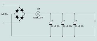
Electrical equipment on the 7E35 planer
The machine is equipped with a three-phase squirrel-cage asynchronous electric motor 4A112M4A.
The following AC voltage values are used on the machine at frequencies of 50…60 Hz:
- three-phase power circuit 220, 380, 400, 440 V
- control circuit 220, 380, 400, 440 V
- local lighting circuit 24 V
The choice of operating voltage of the power circuit and local lighting is made by the customer.
To illuminate the workplace, an SGS-1-1V lamp with a lamp is mounted on the crossbar. In the niche of the crossbar on the working side there are control buttons for starting – “1” and stopping “0” of the main drive and a lamp signaling the switching on of the input machine. The control cabinet is installed on the rear wall of the frame. The supply wires are entered from below through a 1/2″ end connection with a PGV wire with a cross-section of at least 1.5 mm2, black for linear wires and green-yellow for grounding.
7M430 Location of slotting machine controls
Location of controls for slotting machine 7m430
List of controls for the 7M430 slotting machine
- Feed rate setting handwheel
- Mechanism for adjusting table movement to a given processing amount
- Handwheel for manual longitudinal movement of the table
- Mechanical longitudinal feed switch handle
- Reverse handle
- Mechanical circular feed activation handle
- Mechanical cross feed switch handle
- Switch “Lighting”
- “Start” button for quickly moving the table
- Button “Start” of the cutter (duplicated with handle 18)
- Main engine start button
- Cycle switch “Work - Setup”
- Nuts for fixing the rotation of the cutter slide
- Square for turning the cutter sled at an angle
- Hanging “Stop” button of the main engine
- Stops for setting the stroke length of the cutter
- Handle for manual movement of the cutter stroke
- Handle for starting and stopping the cutter
- Handle for steplessly changing the speed of the cutter between stages
- Handle for step change of cutter speed
- Signal light for connecting the machine to the network
- Batch switch for electric pump
- Batch network switch
- Cross slide clamp handle
- Longitudinal slide clamp handle
- Square for manual longitudinal movement of the table
- Square for manual lateral movement of the table
- Dividing mechanism handle
- Round table fixing nuts
§ 1. PURPOSE AND DEVICE OF LONGITUDINAL PLANING MACHINES
The main purpose of longitudinal planing machines is the processing of differently oriented planes, mainly on large parts. The accuracy and cleanliness of machining large-width planes on these machines is higher than the accuracy and cleanliness of machining achieved on milling machines. In addition, the tool (cutter) used on a planer is many times cheaper than a cutter used on a milling machine. Installing large parts and setting up the machine to process a workpiece is easier than a milling machine. These factors are the main reason why more productive milling machines cannot replace planing machines in small-scale and one-off production. The difference in the cost of the tool makes the processing of planes in these industries more economically profitable on longitudinal planing machines than on milling machines.
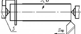
On a longitudinal planing machine, the workpiece is fixed on a table that performs a reciprocating (main) movement. The cutters are fixed in supports. The metal layer is cut off during the working stroke of the table with the workpiece in the direction of the arrow vр.х (Fig. 75). When the table moves back in the direction of the arrow vx.x, the cutter rises, cutting does not occur.
Rice. 75. The main movements when planing on a longitudinal planing machine and the mechanisms that perform them:
1 - cutter, 2 - support, 3 - table, 4 - workpiece
The cutter, together with the support, moves relative to the workpiece being processed after each double stroke of the table by the amount of feed in the transverse direction, thereby ensuring the cutting of a new layer of metal, and so the cycle is repeated.
Thus, a longitudinal planing machine has a mechanism that ensures reciprocating movement of the table together with the workpiece and movement of the cutter (feed) in the vertical or horizontal direction.
Planing machines designed for universal work are divided into four groups according to their design: manual, single-column, double-column and portal. According to the main drive design, longitudinal planing machines are distinguished with double belt (direct and cross) drive and an electromagnetic clutch; with gear transmission and electromagnetic coupling; with multi-speed electric motor and worm gear; with hydraulic drive.
The main brands of longitudinal planing machines produced by the domestic industry are given in Appendix 1.
In what cases is planing competitive with milling?
Indeed, the presence of an idle phase, when the cutter returns to its original position and does not process, significantly improves the position of the direct competitor to planing machines - milling equipment. However, in some cases the use of planing is more appropriate:
- In the case of rough processing of group surfaces on workpieces of the same type, setting up milling machines is more labor intensive than the time spent on servicing planing machines.
- Mechanical processing of workpieces with a surface crust of rust or scale quickly disables the cutters, while the labor intensity of restoration is quite high due to the difficulty of sharpening the tool.
- During planing, the workpiece heats up less intensely, and therefore thermal deformations of the product are insignificant.
- Accordingly, the processing accuracy increases. Energy costs when planing surfaces are significantly lower than when milling them, therefore the drive power of planing machines, compared to milling machines, is also lower.
- Planing machines and tools are cheaper than milling ones, and this is especially justified for small volumes of operations performed.
Download the passport of the planing machine 7B35
Summarizing the above, it is easy to conclude that to obtain small flat surfaces on metal, it is advisable to use their transverse planing. The 7B35 cross-planing machine, produced for a long time by the machine tool plant in Orenburg, is perfectly suited for these purposes.
Brief description of the design of the 7M430 machine
The table moves both manually and mechanically. The circular feed of the table makes it possible to process round parts and gears on the machine.
The machine has hydraulic movement of the cutter and hydraulic feed of the table for each of its double strokes. The kinematic diagram of the machine ensures rapid movement of the table in the longitudinal, transverse and circular directions from a separate electric motor. The table can also be moved manually in the indicated directions. The machine table has a dividing mechanism that allows you to accurately divide the workpiece into the required number of parts.
The speed of movement of the cutter along the entire stroke length is constant. The machine has step-throttle regulation of the speed of the cutter and the movement of the table. Changing the direction of movement of the cutter occurs by switching the control spool using two stops located on the control panel cover. The same stops regulate the length and location of the cutter stroke.
There are two handles on the right side of the machine. One of them serves to switch the speeds of movement of the cutter, there are 4 such speeds in the machine. The other handle smoothly regulates the speed within each step.
The machine has a mechanism that allows you to process the product for a set processing length and automatically turns off the machine at the end of processing; The cutter stops in the upper position. The design of the machine ensures automatic retraction of the cutter from the product during reverse stroke. The machine has a remote control carried out from a pendant push-button station. From the push-button station, the main engine is started and stopped, as well as the cutter is started, stopped and adjusted. The machine has an idle speed limiter - when the cutter stops, the main engine stops. The machine is equipped with a tool cooling system. The lubrication of the cutter guides is forced from a separate reservoir using a plunger pump and manually from a manual lubricator.
Lubrication of the table - from 2 manual lubricators.
Varieties
A metal planing machine can be longitudinally planing or cross-planing. The principle of processing workpieces on these varieties is fundamentally different. Longitudinal planing machines are designed for processing relatively short surfaces, so in them the movement is received by the table to which the workpiece is attached, while the cutter is installed in the cutting head of the support and does not move relative to the machine bed. In a cross-planing machine, the opposite is true: the cutter moves, but the semi-finished product installed on the table is stationary.
Planing machines are inferior to milling machines in productivity because they have an idle stage when the workpiece or cutter moves to a new position. But the drive is not so energy-intensive, because rotational movement of the working tool (as in milling machines) requires increased work from the drive motor.
Read also: How to demagnetize a kinescope at home
The classification of the metal-cutting equipment under consideration can be made according to other parameters:
- By drive type. Units are produced with a hydraulic drive for the movement of the table (or tool), as well as with a crank-rotary drive option. For the former, the speeds of the moving units are constant, while for the latter they can vary according to the characteristics of the processing technology. To do this, it is enough to reinstall the rocker mechanism stone to a new position.
- By the number of working surfaces that can be processed simultaneously. Four-sided metal planing machines can process simultaneously on all edges of a semi-finished product, while double-sided ones can only process on opposite sides. Accordingly, the support of machines of the first type has a more complex design and is designed to install four cutters. Single-sided machines are predominantly small-sized.
- By drive power. Small-sized machines are limited in their functionality, but attract consumers with their low price and compactness, so they can be installed in small metalworking factories, or even in private workshops.
- According to the configuration of the movement of the tool or table. For complex trajectories, shaped metal planing machines are produced, which are equipped with a CNC system. They find application in small-scale production, when it is necessary to obtain complex flat surfaces on products. The qualifications of the worker are not particularly important in this case, since all movements are carried out according to coordinates entered into the system’s memory in advance.
Technical characteristics of the 7M430 slotting machine
| Parameter name | 7403 | 7405 | 7M430 | 7D430 |
| Basic machine parameters | ||||
| Machine accuracy class | N | N | N | N |
| Stroke of the cutter, mm | 120..320 | 120..500 | 120..320 | 120..320 |
| Table diameter, mm | 630 | 800 | 630 | 630 |
| Distance from the table plane to the cutter guides, mm | 500 | 710 | 500 | 500 |
| Distance from the cutter to the frame (reach), mm | 615 | 710 | 590 | 615 |
| Maximum height of the workpiece when processing the outer surface, mm | 500 | 650 | 320 | 500 |
| Maximum height of the workpiece when processing the internal surface, mm | 250 | 325 | 250 | 250 |
| Slotting head of the machine (slotter) | ||||
| Maximum movement of the cutter within the working area, mm | 500 | 700 | 570 | 500 |
| Maximum angle of rotation of the cutter in the direction of longitudinal feed, degrees | 10° | 10° | 10° | 10° |
| Largest cutter section, mm | 32 x 20 | 40 x 25 | 40 x 25 | 32 x 20 |
| Cutter speed under load, m/min | 3..38 | 3..38 | 3..38 | |
| Machine work table | ||||
| Maximum longitudinal movements of the table (along the frame guides), mm | 650 | 800 | 650 | 650 |
| Maximum transverse table movements (along the slide guides), mm | 510 | 650 | 500 | 510 |
| The largest movements of the table are circular, degrees | 360° | 360° | 360° | 360° |
| The cost of dividing the dial for longitudinal and transverse movement of the table, mm | 0,1 | 0,1 | 0,2 | 0,1 |
| Movement of the table per revolution of the dial during longitudinal and transverse movement of the table, mm | 0,7 | 1,4 | ||
| The cost of dividing the dial when moving the table in a circular motion, degrees | 1° | 1° | 1° | 1° |
| Movement of the table per revolution of the dial during circular movement of the table, deg | 0,86° | 0,86° | ||
| Feed limits for one double stroke, longitudinal, mm | 0,1..2,5 | 0,1..2,5 | 0,2..2,4 | 0,1..2,5 |
| Feed limits for one double stroke, transverse, mm | 0,1..2,5 | 0,1..2,5 | 0,2..2,4 | 0,1..2,5 |
| Feed limits for one double stroke, circular, deg | 0,1..1,4° | 0,1..1,4° | 0,1..1,4° | 0,1..1,4° |
| Speed of rapid table movement longitudinal, mm/min | 2,8 | 2,8 | 2,5 | 2,8 |
| Speed of rapid table movement transverse, mm/min | 2,8 | 2,8 | 2,5 | 2,8 |
| Speed of rapid movement of the table circular, rpm | 4,5 | 4,5 | 4,07 | 4,5 |
| Electrical equipment. Drive unit | ||||
| Number of electric motors on the machine | 3 | 3 | 3 | 3 |
| Hydraulic drive electric motor (main movement), kW (rpm) | 11 (970) | 11 (970) | 7 | 10 |
| Electric motor for rapid table movement, kW | 2,2 | 3,0 | 1,7 | 2,2 |
| Coolant electric pump electric motor, kW | 0,12 | 0,12 | 0,12 | 0,12 |
| Total power of all electric motors, kW | 13,32 | 14,12 | ||
| Dimensions and weight of the machine | ||||
| Machine dimensions (length width height), mm | 2850 x 2160 x 3010 | 3440 x 2760 x 3465 | 2650 x 1810 x 2890 | 3030 x 2175 x 3010 |
| Machine weight, kg | 5660 | 8160 | 5200 | 5700 |