Using devices
Wellhead fittings are used not only for working with an oil pipeline. It can also be successfully used to conduct deep research, for example. Another option for using it is to adjust the fluid intake. All these examples quite clearly show that the use of wellhead equipment is an integral part of oil production.
It is important to add that the selection of such devices is carried out according to special criteria, and all of them are distinguished by the fact that the quality of their production is very high, as is their productivity. For example, the operating temperature range at which wellhead equipment is able to perfectly perform its functions is in the region from -60 to +40 degrees Celsius. In other words, they can be used in almost any climate.
The meaning of fountain pipes
Even with the same amount of gas content in the formation, not every well is capable of flowing. For example, if the volume of such gas is sufficient to ensure flowing in a well of 150 mm in diameter, then it may not be enough for a diameter of 200 mm.
The gas-oil mixture that moves along the wellbore looks like a layer-by-layer alternation of oil and gas layers. Therefore, the larger the diameter of the production pipe string, the greater the amount of gas required to lift the oil liquid through it.
Read also: How to properly use a thermometer for petroleum products?
In practice, there have been cases in which wells with large bore diameters (from 150 to 300 millimeters), which were drilled to a depth with highly productive formations with high internal pressure, were distinguished by high flow rates, but even in them, flowing most often continued to be quite a short time. Moreover, in some cases, wells drilled into productive formations with high pressures cannot flow out under normal conditions.
In this regard, in order to make the most efficient use of the energy of the expanding gas, all mine workings where blowouts are possible are equipped before development with lift pipes, the nominal diameters of which vary from 60 to 114 millimeters. It is through these small-diameter pipes that the gas-liquid mixture moves in the drilled well.
The selection of the diameter of lifting (elevator) pipes occurs, as a rule, experimentally, and depends on the following factors of a specific mine working:
- expected well flow rate;
- reservoir pressure value;
- drilling depth;
- specific operating conditions.
During the process of well flowing through a small-diameter pipe string, the gas factor decreases, which makes it possible to extend the flowing time period. In many cases, a well flowing through a pipe string with a diameter of 73, 89 or 114 millimeters first began a regime of periodic emissions, and then it stopped completely. In such cases, the duration of the fountain was extended by replacing these pipe columns with fountain pipes of smaller diameters (33, 42, 48 and 60 millimeters).
Basic parameters of the device
The main defining characteristic for wellhead fittings was size. The average length of such a device is about three meters. As for the width, it naturally varies depending on the model, but the approximate average is 715 millimeters. The last indicator in terms of dimensions is the height, which is on average 1.5 meters.
Another important indicator for this equipment is the passage of the locking device. The numerical value of this parameter can reach up to 50 millimeters. Along with wellhead fittings, equipment such as pumping and compressor equipment is also used for the well. The pipe diameter of such devices can reach up to 75 mm. It is worth noting that this type of fitting is not a specific device, but a set of several important components that perform purposes such as sealing the wellhead. In addition, the fittings will be responsible for distributing the flow of substances that will come from the well. You can also regulate such a volatile substance as gas, for example.
AUESP
Wellhead fittings for installing an electric pump (65)x14 LZ
The wellhead fittings are designed for installation at the wellheads of wells with submersible ESP, monitoring and regulating the operating mode, as well as carrying out technological operations, research and repair work.
The fittings are equipped with a lubricator valve (at the buyer’s request) and a manifold with a pipeline equipped, depending on the assembly diagrams, with devices, pressure gauges, quick-release connections, and a check valve
The valve body is of welded construction with side outlets for fastening corner valves. The housing flange has seating and sealing surfaces for installation of process equipment. The sub for fastening tubing pipes is installed in the housing and has holes for entering cables or devices.
Equipment design
When it comes to the design of this device, there are several main components. These include, for example, a pipe-type head, a column-type head and a head of the valve itself. The valve head is of the adjustable-shut-off type. Even such small devices as valves, gate valves and some other small parts of this kind can be distinguished as components.
The main purpose of wellhead fittings is to contain a strong flow of pressure, as well as the ability to study this pressure inside the structure itself. To operate this type of valve, a mechanical drive is usually used. However, it happens that the pressure is too high. In this case, it will be restrained either using pneumatic type installations or using a hydraulic system. It is also worth saying that there may be wellhead injection valves. In this case, it is capable of performing the functions of injection or release of gas flows.
Flowing Well Study
The flowing well design requires regular studies, which are carried out using the method of test pumping of liquid and the method of restoring pressure in the bottom hole after the equipment is stopped. Specialists adjust the operating mode by changing fittings and installing elements with holes of different sizes. The test pumping method can be successfully used to identify the degree of productivity of a well and determine the optimal mode of its operation. As for the method of restoring the pressure level, it can be used to calculate the main characteristics of the formation.
The procedure for selecting liquid for research is carried out using special devices that are fixed and lowered like a pressure gauge. Lowering the pressure gauge itself requires a lubricator in the design, which will be equipped with an oil seal with a roller. The gland acts as a sealing agent for the hole through which the wire is passed. If it is necessary to carry out deep research, it is necessary to use a mechanical lifting winch, which is placed 20-30 meters from the mouth.
First, the template is lowered down, then the measuring device (sometimes with a weight). To prevent the wire from breaking during the study, the equipment must not be lowered below the edge of the pipe. To prevent this phenomenon, the shoe is equipped with a special pin that limits the descent inside the column. The lifting is carried out at low speed; in the last meters it should be minimal (in some cases, research devices are pulled out manually).
The flow rate is measured in group installations, and a tap is used for sampling, which takes a sample of the liquid and gives the result after some time.
Features of the device
It is worth highlighting one very important advantage of this type of fittings. If any element fails during operation, it can be replaced without taking the entire station out of service. This is one of the most important criteria, since in this case it becomes possible to carry out repair work without disrupting the time interval of the station’s operation. This is one of the main requirements in the oil production environment. In addition, this helps to save a significant amount of material resources that would have been lost while the station was idle for repairs.
The structure itself is tied together using a variety of clamps and different flanges. It is also worth highlighting here that if in the entire structure any element has a deviation from the nominal data, then all other devices belonging to the locking type and all other mechanical elements will be disabled. An automatic system is responsible for this, which is equipped with any fittings of this type.
Brief information
GBU RT "Social Assistance Center of Kyzyl" was registered on July 7, 2003 by the registrar INTERDISTRICT INSPECTION OF THE FEDERAL TAX SERVICE No. 1 FOR THE REPUBLIC OF TUVA. Head of the organization: director Saryglar Orlanmaa Belek-Oolovna. The legal address of the State Budgetary Institution of the Republic of Tajikistan “Social Assistance Center of Kyzyl” is 667011, Republic of Tyva, Kyzyl city, Bai-Khaakskaya street, building 6.
The main type of activity is “Other care activities with provision of accommodation”. The organization STATE BUDGETARY INSTITUTION OF THE REPUBLIC OF TUVA “CENTER FOR SOCIAL ASSISTANCE FOR FAMILY AND CHILDREN OF KYZYL CITY” was assigned TIN 1526939068, OGRN 3181933751031, OKPO 12923612.
Fountain type fittings
Today there is such a type of fittings as wellhead fountain. It, in turn, is divided into several types. It can be a tee type or a cross type. The choice depends on which fountain tree was chosen. It can also be either double-row or single-row. This is determined by the number of pumping tubular products that will be lowered down into the well. The equipment can be taps or valves, that is, it differs in the type of locking device. The difference between this type of fittings is that the through hole can be from 50 to 150 mm. Used at pressures from 14 to 140 MPa.
Aushgn fittings purpose device
GOST 13846-89 (ST SEV 4354-83)
STATE STANDARD OF THE UNION OF THE USSR
MOUTHOW AND DISCHARGE FITTINGS
Typical diagrams, main parameters and technical requirements for the design
Gush and injection well equipment. Standard schemes, basic parameters and technical requirements for construction
OKP 36 6513, 36 6514, 36 6666
Validity period from 01.01.90 to 01.01.95* _______________________________ * The validity period was lifted according to Protocol N 4-93 of the Interstate Council for Standardization, Metrology and Certification (IUS N 4, 1994). — Note "CODE".
1. DEVELOPED AND INTRODUCED by the Ministry of Chemical and Petroleum Engineering of the USSR
R.D. Dzhabarov, Ph.D. tech. sciences; A.G. Dozortsev, Ph.D. tech. Sciences (topic leader); T.K.Veliev, Ph.D. tech. Sciences (topic leader); S.M. Osipova; L.G.Sharonova
2. APPROVED AND ENTERED INTO EFFECT by Resolution of the USSR State Committee on Standards dated 02.24.89 N 332
3. The verification period is 10/01/93.
The inspection frequency is 5 years.
4. The standard fully complies with ST SEV 4354-83
This standard applies to wellhead Christmas tree and injection valves, consisting of a wellhead tree and piping, regardless of the area of application in climatic region and operating environment.
This standard does not apply to wellhead equipment with parallel suspension of well pipelines; for production or injection of coolant, as well as installed on wells with an underwater mouth location.
TYPICAL DIAGRAMS AND MAIN PARAMETERS
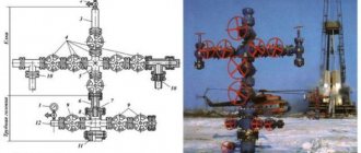
1.1. Typical diagrams of fountain trees should correspond to those shown in Figure 1, and of injection trees - in Figure 2.
Typical diagrams of fountain trees
1 — sub to the pipe head; 2 - tee; 3 - locking device; 4 — pressure gauge with shut-off and discharge device; 5 - throttle; 6 — counter flange; 7 — cross
Typical diagrams of injection trees
1 — sub to the pipe head; 2 - tee; 3 - locking device; 4 - pressure gauge with shut-off and discharge device; 5 - check valve; 6 — counter flange; 7 — cross
1.2. Typical piping diagrams for Christmas tree and injection valves must correspond to those shown in Figure 3.
Typical Xmas tree piping diagrams
1 - counter flange; 2 - locking device; 3 - pipe head; 4 — pressure gauge with shut-off and discharge device; 5 - quick connection
1.3. Typical diagrams of wellhead fittings should be compiled by a combination of standard diagrams of wellhead trees with piping.
Examples of typical diagrams of Christmas tree fittings are shown in Fig. 4, of injection fittings - in Fig. 5
1 - fountain tree (Fig. 1); 2 - piping (Fig. 3)
1 — injection tree (Fig. 2); 2 - piping (Fig. 3)
1.4. The main parameters of the Christmas tree fixtures must correspond to those indicated in Table 1.
Conditional bore, mm
Working pressure, MPa
side branches of the tree
side outlets of the pipe head
14, 21, 35, 70, 105
14, 21, 35, 70, 105, 140
1.5. The main parameters of injection valves must correspond to those indicated in Table 2.
Conditional bore, mm
Working pressure, MPa
side branches of the tree
side outlets of the pipe head
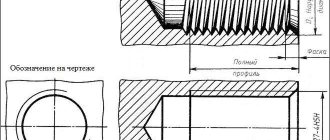
1.6. Symbols of wellhead trees and fittings must consist of a name, a code constructed according to the scheme in Appendix 1, and a designation of a regulatory and technical document for supply.
Examples of symbols
Christmas tree with suspension of the well pipeline in the pipe head, with a Christmas tree according to standard scheme 6, with automatic control, with a nominal bore of 80 mm and side branches of 65 mm, for a working pressure of 70 MPa:
Fountain fittings AF6A-80/65x70
GOST 13846-89
Trees with a well pipeline suspended in a sub to a pipe head (reel-pipe holder), made according to standard scheme 2, with manual control, with a nominal bore of 65 mm, side branches of 50 mm, for a working pressure of 35 MPa, corrosion-resistant design K2:
Christmas tree EFK2-65/50x35K2
GOST 13846-89
Injection fittings with suspension of the well pipeline in a sub to the pipe head, made according to standard scheme 1, with manual control, with a nominal diameter of the trunk and side branches of 65 mm, for a working pressure of 21 MPa:
Injection fittings ANK1-65x21
GOST 13846-89
The same, with two pipe heads according to Fig. 4b:
Injection fittings AHK1a-65x21
GOST 13846-89
Injection tree with the same parameters and purpose:
Injection tree ENK1-65x21
GOST 13846-89
TECHNICAL REQUIREMENTS FOR DESIGN
2.1. The nominal diameters of the connecting flanges of wellhead fittings are given in Appendix 2.
2.2. The design of the wellhead fittings must ensure complete tightness with respect to the environment.
2.3. The design of the body parts of the wellhead fittings must ensure the possibility of their pressure testing with the test pressure given in Table 3.
Devices for injection wells
The main purpose of this type of fittings is to seal injection wells. A special feature is that all work can be carried out while water is being pumped into the well. The main parts of the equipment include the pipe head and the tree. The first element is used to seal the annulus. It is also necessary to perform certain repair work, research work, and some technological operations. This element consists of components such as latches, a cross and several elements for quick connection.
Wellhead double-barreled fittings
The utility model relates to the field of mechanical engineering, in particular to wellhead fittings, and can be used in the oil industry for piping the wellhead equipped for simultaneous separate production and injection, and allows for regulating the operation of the well, its flushing and testing. The technical objective of the claimed utility model is the use of wellhead double-barreled valves as a wellhead piping for the production of formation fluid by a screw rod pump driven by a rotational path from a surface drive and a working agent into the receiving well formation. The stated technical problem is solved by the described wellhead double-barreled fittings containing a lower cross, a pipe hanger, a special pipe hanger, an injection tee with a plug, a production cross with a check valve and bends. What is new is that the production spider is provided with a flange or top thread, internal or external, to accommodate the ground drive of the screw rod pump.
The utility model relates to the field of mechanical engineering, in particular to wellhead fittings, and can be used in the oil industry for piping the wellhead, equipped for simultaneous separate production with a screw pump and injection of a working agent, and allows for regulating the operation of the well, its flushing and testing.
The well-known “Wellhead fittings AU 140x50” (analogue) for single-lift operation of wells with screw pumps, consisting of a housing, a pipe holder, a tee and shut-off devices (passport 2173-00-00PS LLC Tatneft-RBO).
The disadvantage of wellhead fittings is their unsuitability for simultaneous separate production with screw pumps and at the same time injection of the working agent into the well, because One tee with a mating flange is used to serve as the base of the surface drive.
It is known “Wellhead equipment with parallel pipe suspension” (AS SU 375369, E21B 33/03, published bulletin 16 of March 23, 1973), including a pipe holder of the first row of pipes, a pipe holder of the second row of pipes with flanges, a reel with flanges, a sealing nipple, wherein the upper flange of the coil is placed eccentrically relative to the axis of the coil, and the lower flange of the pipe holder of the second row of pipes is eccentrically relative to the axis of the pipe holder of the second row of pipes.
The disadvantages of this device are:
firstly, high metal consumption and design complexity due to the large number of parts, which reduces the reliability of the entire device as a whole;
secondly, the complexity of hoisting operations, since it is necessary to disconnect at least one of the flanges of one pipe holder to carry out hoisting operations even with one row of pipes connected to the pipe holders;
thirdly, the difficulty of docking surface equipment to the device due to the small center distance between the axes, limited by the internal diameter of the well casing pipes and the diameter of the pipes in the rows;
fourthly, the unsuitability for simultaneous-separate production of wells with screw pumps driven by a rotational path from a surface drive with simultaneous-separate injection of the working agent.
The well-known “Double-barreled wellhead fittings” (RF patent 2305747, E21B 33/03, published on September 10, 2007), including a pipe holder of the first row of pipes with two channels, one of which is equipped with upper and lower threads, and a pipe holder of the second row of pipes with an upper and lower threads. The specified fittings are closer in technical essence to the proposed double-barreled wellhead fittings, and it can be taken as a prototype.
The disadvantage of the known device is that it is unsuitable for well production using screw rod pumps driven by a rotational path from a surface drive with simultaneous separate injection of the working agent.
The technical objective of the claimed utility model is the use of wellhead double-barreled valves as a wellhead piping for the production of formation fluid by a screw rod pump driven by a rotational path from a surface drive and a working agent into the receiving well formation.
The stated technical problem is solved by the described wellhead double-barreled fittings containing a lower cross, a pipe hanger, a special pipe hanger, an injection tee with a plug, a production cross with a check valve and bends.
What is new is that the production spider is provided with a flange or top thread, internal or external, to accommodate the ground drive of the screw rod pump.
Figures 1-4 show the upper part of the described double-barreled wellhead fittings (options), figure 5 shows the described double-barreled wellhead fittings according to figure 1, general view.
The wellhead double-barrel fitting (Fig. 1-4) contains a pipe holder 1, a special pipe holder 2, a cross for production 3 with an outlet 4 and a check valve 5, as well as a tee for injection 6 with a plug 7 and an outlet 8.
In the case of production along a long string of tubing pipes 9, a crosspiece for production 3 is screwed into the pipe holder 1 (Figs. 1 and 3), and a tee for injection 6 is screwed into a special pipe holder 2.
In the case of production along a short tubing string 10, a tee for injection 6 is screwed into the pipe holder 1 (Figs. 2 and 4), and a crosspiece for production 3 is screwed into a special pipe holder 2.
The production cross 3 can be made with a flange 11 (Figs. 1, 2 and 5) or with a top thread (external 12 or internal 13) (Figs 2 and 4) for mounting with a ground drive (not shown). The flange 11 can be connected to the mining cross 3 detachably, permanently, or manufactured together as a single piece.
The pipe holder 1 is connected to the lower cross 14 (Fig. 5). The lower cross 14 serves to connect the wellhead double-barreled fittings assembly with a thread 15 to the well casing coupling (not shown in the figures) and seal the annulus, and is equipped with bends 16 and 17.
Wellhead double-barreled valves work as follows.
The produced formation fluid (Figs. 1 and 3) enters through a long string of tubing pipes 9 and through the production cross 3 and outlet 4 enters the oil pipeline (not shown). Through the outlet 8 and the tee for injection 6 along a short string of tubing pipes 10, the working agent (water, steam, etc.) is supplied to the receiving formation of the well (not shown).
The produced formation fluid (Figs. 2 and 4) enters through a short string of tubing pipes 10 and through the production cross 3 and outlet 4 enters the oil pipeline (not shown). Through the outlet 8 and the tee for injection 6 along a long tubing string 9, the working agent is supplied to the receiving formation of the well (not shown).
The use of the proposed technical solution allows the well to be operated using highly efficient methods, for example, installing a screw rod pump with a surface drive with simultaneous separate injection according to utility model patent 84461 dated February 6, 2009 “Installation for simultaneous separate production and injection through one well,” according to application 2009104091, IPC E21B 43/14, author - A.A. Isaev. For information, graphic images of these settings are attached on 2 sheets in 3 copies.
Wellhead double-barreled fittings containing a lower cross, a pipe hanger, a special pipe hanger, a tee for injection with a plug, a cross for production with a check valve and bends, characterized in that the cross for production is equipped with a flange or top thread, internal or external, for installing a surface screw drive sucker rod pump.