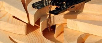
Reinforcement made of different grades of steel with a wide range of thicknesses is used to reinforce concrete and brickwork. Portland cement is a versatile material for use in the construction of foundations, buildings, and much more. But it is prone to cracking and breaks when bending.
There was a need to take additional measures - to reinforce concrete. It provides tensile, torsional, and shear strength. At the same time, it is possible to reduce concrete consumption and, as a result, construction time.
Reinforced concrete products are a complex composite structure. Its structure contains reinforcement bars, which are surrounded by a concrete shell. The type of reinforcing bar profile and its geometric characteristics affect the strength of the product, its resistance to cracks and deformation.
Reinforcement classes
Since 2022, the new standard GOST 34028-2016 has been in force. Not only the designation of classes (1) has been changed. Old markings according to GOST 5781-82: A-I, A-II, A-III, A-IV, A-V, A-VI.
Table 1. Last positions - rope reinforcement.
Changes have also occurred in these indicators.
- Surface coating of reinforcement.
- Labeling.
- Bending-bending tests.
- The classes are not tied to a specific steel grade. Only its chemical composition is recommended. This allows you to react flexibly and implement innovations in the domestic and foreign steel industry.
- A direct ban has been introduced on the production of reinforcement from rails and sheet scraps.
- It is allowed to produce fittings with a profile shape different from the 4 standard ones.
Now, instead of meaningless Roman numerals behind the letter A: I, II, III, the yield strength is indicated: 240, 300, 500. The numbers indicate strength characteristics: yield strength in N/mm2. This is the ultimate load, after a slight excess of which irreversible plastic deformation begins, or, more simply, destruction.
The higher this indicator, the stronger the reinforcement.
For clarity, the recommended replacements are summarized in Table 2.
table 2
Another goal of the changes in the standard is to bring domestic and European requirements as close as possible.
Reading the results of fittings selection
Tags: #LIRA-SAPR #ARM-SAPR #reinforcement #results
Reading the results of selecting longitudinal reinforcement for bars
The results of selecting reinforcement for bars are entered in three lines:
- LINE 1 - complete reinforcement in section;
- LINE 2 - reinforcement selected according to group I of limit states;
- LINE 3 - reinforcement due to torsion (o). * Transverse torsion reinforcement – cross-sectional area of a closed external clamp.
Result line structure:
ELEMENT—element number in the design diagram; SECTION - number of the reinforced section of the rod element; C/N symmetrical and asymmetrical reinforcement; The sign * indicates reinforcement due to torsion.
LONGITUDINAL REINFORCEMENT - area of selected longitudinal reinforcement (cm2) and percentage of reinforcement.
Layout of reinforcement in relation to the local axes of the rod
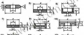
AU1 is the area of the corner lower longitudinal reinforcement (in the lower left corner of the section - opposite the Z1 and Y1 axes); AU2 is the area of the corner lower longitudinal reinforcement (in the lower right corner of the section - against the Z1 axis and in the direction of the Y1 axis); AU3 - area of the corner upper longitudinal reinforcement (in the upper left corner of the section - against the Y1 axis and in the direction of the Z1 axis); AU4 - area of the corner upper longitudinal reinforcement (in the upper right corner of the section - in the direction of the Z1 and Y1 axes);
Corner reinforcement is displayed only for those bars for which the “Select corner reinforcing bars” checkbox is set in the “Type” reinforcement parameters.
AS1 is the area of the lower longitudinal reinforcement (the lower edge opposite the direction of the Z1 axis); AS2 is the area of the upper longitudinal reinforcement (the upper edge in the direction of the Z1 axis);
If the “Select corner reinforcing bars” attribute is not set in the “Type” material, then the area of the corner bars is included in the area of the lower AS1 and upper AS2 reinforcement.
AS3 - area of lateral longitudinal reinforcement (left side opposite the direction of the Y1 axis); AS4 - area of lateral longitudinal reinforcement (right side in the direction of the Y1 axis).
For bars there are 2 options for the reinforcement algorithm: 1. “Discrete reinforcement” – enabled by default (the “select corner bars” checkbox is enabled), in this case the area of corner bars is not included in the reinforcement areas at the faces, and is displayed separately as areas AUi. 2. “Distributed reinforcement” – disabled by default (you need to turn off the “select corner bars” checkbox), in this case the area of the corner bars is included in the area of the upper (As2) and lower (As1) reinforcement. In the general case, “discrete reinforcement” is more economical, since it first builds up corner bars (which work more efficiently for oblique bending and torsion, i.e. with a large shoulder) until they hit the constraint of the corner bar specified in the “Reinforcement” material. . And only then does the reinforcement build up between the corner rods begin. And if “distributed reinforcement” is enabled, then during selection all reinforcement areas are built up at the faces As1 and As2 (i.e., corners and between them).
TRANSVERSE REINFORCEMENT - areas of transverse reinforcement. ASW1 - vertical transverse reinforcement (along the Z1 axis); ASW2 - horizontal transverse reinforcement (along the Y1 axis);
CRACK WIDTH - width of short-term and long-term crack opening (mm).
Recommendations for selecting reinforcement for rods
The main influence on the result of selecting the reinforcement of the rod is exerted by the c.t. binding. reinforcement to the section face. This value should be assigned taking into account the requirements of regulatory documents on the size of the protective layer, see SP 63.13330.2012 clause 10.3.2, table. 10.1. For preliminary calculation, it is recommended to set the c.t. reference. reinforcement rod 5 cm. After obtaining the result in the form of the required reinforcement area, you should determine how many rods of the selected diameter can cover the required reinforcement area. After selecting the required number of rods, they should be arranged within the dimensions of the rod section. If it was originally planned to install the rods in one row, then you should check whether they can be placed in one row, but in such a way that the requirements for the minimum distance between the rods in the structure are met - see SP 63.13330.2012, clause 10.3.5.
If the arrangement of the rods in compliance with all requirements cannot be fulfilled, then changes should be made to the design:
- change concrete/rebar classes;
- increase the cross-section of the element;
Recommended distance to center point. reinforcement should be installed so that the thickness of the protective layer of concrete is a multiple of 5 mm. The reinforcement clamps have a height that is a multiple of 5 mm, but the height is measured to the bottom edge of the reinforcement, as a result of which it is necessary to add c to the binding value. t. reinforcement half the diameter of the rod.
How to choose the diameter of the reinforcement
If the calculation is performed only according to group I of limit states, then the diameter of the reinforcement should be selected based on the possibility of arranging the reinforcement in the section. If the calculation is carried out according to group II of limit states, then when arranging bars in a section, you should use bars with a diameter not exceeding the diameter specified when specifying the characteristics of materials for the calculation of reinforced concrete. designs.
Reading the results of selecting longitudinal reinforcement for plates
Results line structure:
ELEMENT—element number in the design diagram; LONGITUDINAL REINFORCEMENT - areas of selected longitudinal reinforcement.
Layout of longitudinal reinforcement of slabs and shells
AS1 is the area of the lower (for beam-walls in the middle) reinforcement in the X direction (cm2/pm); AS2 is the area of the upper reinforcement in the X direction (cm2/pm); AS3 is the area of the lower (for beam-walls in the middle) reinforcement in the Y direction (cm2/pm); AS4 is the area of the upper reinforcement in the Y direction (cm2/pm);
TRANSVERSE REINFORCEMENT - areas of transverse reinforcement: ASW1 - transverse reinforcement in the X direction (cm2/rm); ASW2 - transverse reinforcement in the Y direction (cm2/pm);
Recommendations for selecting plate reinforcement
The recommendations are similar to those given above for rods, with the only difference that when calculating plates according to group II of limit states, when assigning materials, the pitch of the rods should be set equal to the pitch of the background reinforcement adopted in the project. The program will select the required diameter of the rod, which, with the selected step, will provide the required reinforcement area. It is allowed to accept a smaller diameter of the reinforcement and place it in smaller increments than was originally accepted. After selecting the pitch/diameter combination, you should adjust the center of gravity bindings. reinforcement and perform a re-calculation, the results of which make sure that the selected reinforcement ensures that the requirements for strength and crack resistance are met.
Fragment of the window for setting up materials for calculating reinforced concrete. structures type PLATE
Reading the results of selection of transverse reinforcement
The version of the calculation for shear force implemented in LIRA SAPR assumes the following:
- a number of inclined sections are constructed from each design section of the rod;
- the projection of the inclined section C varies from ho to 2ho;
- by searching with a change in C by 10%, the following are calculated: Qb→Qsw=Q-Qb→qsw=Qsw/(C*φsw)→(Asw/sw)=qsw/Rsw;
- the calculated transverse reinforcement is taken to be max from the obtained Asw/sw [cm2/1.m.p.] (Asw/sw is the intensity of transverse reinforcement per 1 m.p.)
For rods
to go to a specific reinforcement diameter, you should set the step sw, then Asw=(Asw/sw)*sw. Knowing Asw and the number of clamp cuts in the cross section n, the area of one rod Asw,i=Asw/n[cm2].
But you should also check whether there is enough transverse torsional reinforcement, because torsional reinforcement must be provided with a closed clamp, therefore line 3 displays the area of one closed clamp with different spacing along the rod element. Those. you need to select from line 3 the maximum value of vertical (ASW1) and horizontal (ASW2). At one face of the element, the area of the outermost transverse rod Asw,i must be larger than required for torsion.
For example, we got the result:
Those. Asw1/sw=8.8cm2/1m.p. We take the step sw=0.2m, then Asw=8.8*0.2=1.76cm2. With 4 clamp cuts (n=4) Asw,i=1.76/4=0.44cm2→d8A240C c Asw,i=0.503cm2.
Let's check the sufficiency of transverse torsional reinforcement: Reinforcement based on torsional strength: Asw*=3.24*0.2=0.648cm2>Asw,i=0.503cm2 Because Asw* is reinforcement at one face, then we finally accept the clamp d10A240C with Asw,i=0.785cm2.
For plates
It should be remembered that the results are displayed on 1p.m. element width, and the area of transverse reinforcement was obtained with a rod spacing of 100 cm (Asw/sw). Those. when determining the diameter of the rod, you should specify the pitch of the rods along the inclined section and across it (sw and sw┴).
So, if the required transverse reinforcement is 100 (cm2/1.m.p.)/1m. width, the pitch of the rods in the direction of the inclined section is 0.06 m, and in the perpendicular section 0.1 m, then the area of one rod Asw,i=(100*0.06)*0.1=0.6cm2.
When you check the Select transverse reinforcement per 1 sq.m checkbox in the General characteristics dialog box when setting parameters for reinforced concrete structures, transverse reinforcement is selected per 1 m2 (Asw). The design spacing of transverse reinforcement is taken to be 1 meter to facilitate the transition to an arbitrary spacing of transverse reinforcement.
Instructions for averaging transverse reinforcement in plates:
Functionality
For reinforcement of precast concrete, reinforcement up to class A600 is used. Classes above this are built into prestressed reinforced concrete structures.
Types of fittings by purpose.
- Working (longitudinal and transverse): accepts the main types of loads in a reinforced concrete product, the diameter is determined by calculations.
- Assembly (distribution and structural): for the formation of three-dimensional frames and meshes.
- Distribution: ensures the correct location of the working rods.
- Structural: not calculated; installed in places that may be subject to random loads.
- Anchor: for the formation of embedded elements, including gripping loops.
The consumption of reinforcement of all types in reinforced concrete structures ranges from 50 to 80 kg per cubic meter of concrete, but not less than 8 kg. The calculation of the required quantity for a strip foundation is given below.
Reinforcement range: additional marking options
To determine more specific characteristics of the reinforcement, a special additional marking system has been created. For example, the abbreviation A5K means that these are class A5 profiles, and the letter K indicates the presence of additional corrosion protection. To do this, the material is treated with special agents that ensure its durability.
The presence of the letter C in the marking indicates that the reinforcement can be welded. It must be taken into account that not all products belonging to different classes can be welded together, especially in the absence of the C mark in the designation.
If the marking contains the letter K, this means that the reinforcement has additional corrosion protection
Speaking about the range of fittings, we should mention such a term as shut-off (or pipeline) valves. These types of profiles are used in plumbing work. Accordingly, as a separate subtype of material, this reinforcement has its own classes and markings. In this case, the main parameter of choice is tightness. This criterion indicates the quality of the assembly in the pipeline, without which it is impossible to assemble it. The tightness indicator is indicated in the characteristics on the packaging of the material.
Helpful advice! It is better to connect reinforcing bars with different markings and in the absence of the letter C in the designation, using special couplings and wire.
Marking
To inform consumers about the special properties of metal products, manufacturers additionally label them.
- A – rolled reinforcement.
- AP – rolled products for prestressed structures.
- H – increased category of plasticity.
- E – high plasticity for earthquake-prone areas.
- K – corrosion-resistant, with a protective coating (galvanized, galvanized).
- U – resistant to cyclic loads.
- C – weldable.
- T – compacted by thermal or mechanical means.
The letter designation of additional characteristics follows the numbers indicating the yield strength.
Markings are present on each rod. Each class is assigned a number (3)
Table 3
On one of the sides between profile ribs of increased thickness or ribs with a changed direction, ribs of normal size are considered. Their number - in accordance with Table 2 - means the class of the reinforcement.
Rice. 2
Rice. 3
The standard recommends such an encrypted designation, i.e. in practice you will encounter something else: cast numbers.
Rice. 4
In the accompanying documentation, fittings are designated by a set of numbers and letters. Let's look at a few examples.
- 10-A240 GOST 34028-2016. Smooth reinforcing bars in coils or bars with a diameter of 10 mm, class A240.
- 1f-12-A500 GOST 34028-2016. Periodic profile of the form 1f class A500, in rods or coils.
- 1f-12-A500SN. The same, weldable, increased ductility.
The marking may contain a measured (MD) or other length, production method.
Technical requirements for reinforced type reinforcement
Reinforced reinforcement products are made exclusively from low-alloy steels:
- At800: 08G2S, 10GS2, 20GS, 20GS2, etc.;
- At800K: 25S2R, 35GS;
- At1000: 20GS, 20GS2, 25S2R;
- At1000K: 20HGS2;
- At1200: 30ХС2.
Strengthened smooth type reinforcement in terms of parameters such as tensile strength (N/mm2), yield strength (N/mm2), relative and uniform elongation (%) must correspond to the following values:
- At800: 1000; 800; 8; 2;
- At1000: 1250; 1000; 7; 2;
- At1200: 1450; 1200; 6; 2.
Smooth reinforcement of these types is also checked for bending, for which a mandrel with a diameter of 5d is used, and the product itself is bent at an angle of 450.
A very important requirement for reinforced reinforcement, manufactured with a smooth profile, is that such products should not collapse even after 2 million cycles of stress applied to them, the value of which should be at least 70% of the value of the ultimate tensile strength (nominal) , which corresponds to the material of the rod.
Delivery status
An area where the private developer almost always faces unpleasant discoveries.
The reinforcement is supplied in coils (up to 22 mm thick) and rods. The skein should consist of one, maximum two segments.
Length of rods: 6 - 18 m. Rods according to standard 34028-16 come in measured length (MD), measured with unmeasured (MD1), unmeasured (ND, 6 - 12 m). In the supply of MD1, no more than 3% of unmeasured rods with a length of at least 2 m are allowed.
Rods of irregular length are cheaper. But the probability of deception here is quite high. If it is not possible to count and measure each rod, you will pay more. Please also take into account that due to the overlap of individual rods, the consumption of reinforcement will increase.
The skeins should unwind freely, and the overlap of the turns should not interfere with unwinding.
How much does a meter of reinforcement weigh and how many meters of reinforcement per ton: examples of calculations
Skills in calculating the diameter of the rods will also be needed when calculating the weight of the reinforcement. Such knowledge is necessary when drawing up projects and construction estimates. Accurately determining the weight of the reinforcement will help you save on the purchase of materials. It is important to note the fact that large manufacturers sell reinforcement at a price of 1 ton, and not per meter. However, the cost of production in this case will be several times cheaper.
As an example, we can consider how to calculate the mass of the necessary material for the construction of a reinforced concrete foundation with a total length of 100 m. The diameter of the reinforcement is 10 mm. We look for the necessary data in the table, they correspond to 617 g. We multiply this number by 100 and get 61 kg 700 g. The weight of 1 meter of reinforcement can be calculated in other ways (there are three in total):
- according to the normative table;
- using data on the specific gravity of reinforcement;
- using the reinforcement weight calculator.
Thanks to accurate calculations of the required weight of the reinforcement, you can save on the purchase of material
The required number of rods by standard weight is calculated using the above weight table in relation to the linear meter. This is the simplest calculation option (except for an online calculator).
For example, for construction it is expected to use 2300 m of reinforcement 14. The weight of 1 meter of rods is 1.21 kg. We make calculations: 2300 * 1.21 = 2783 kg. Thus, to complete this volume of work, 2 tons of 783 kg of steel rods will be required. The number of rods in one ton of the corresponding diameter is calculated in the same way. The data is taken from the table.
Fittings for private housing construction
Of the 15 positions (Table 1), four are enough for an individual developer.
- A240 (Commonly AI). Hot rolled smooth. Distribution, anchor for embedded parts, diameter 6-8 mm. Bay.
- A400 (AIII). Hot rolled, periodic profile. Working, diameter 10-12 mm. Rods 12 m long.
- A500 (AIII). See point 2.
- В500 (ВрI). Wire for masonry, reinforcing mesh. Diameter 3-5 mm. In the form of ready-made meshes.
It is recommended to purchase fittings by the metre. This is time consuming. But it guarantees that exactly the footage that is needed is paid for.
When bending rods, it is recommended to adhere to the radii and angles indicated in Table 4 for welded reinforcement (C) with a special notch.
Table 4
These tables will help to distinguish low-quality fittings. Rods made from melted down rails break at smaller angles. It belongs to class 500.
A400 class rods cannot be welded; the bending angle should not exceed 90°.
Universal class
A500C is the most popular fittings. Due to its lower carbon content, it is perfectly welded together (including arc welding), which strengthens the frames for the concrete structure.
A reduced amount of alloying additives has increased ductility; brittleness is not inherent in it. This is clear from αmax, which is 180°. This additionally makes it possible to use this class as anchor reinforcement.
A500 can replace A400 without recalculating design loads. At the same time, reverse replacement only with a new calculation. Due to the increased strength of A500, up to 10% of material can be saved on reinforcement. This is a significant value for any project.
It is also important that the A500 is operated at -55 ° C, which is 10 ° lower than the A400.
Weldable reinforcement is 15% more expensive than conventional reinforcement of the same class. But the A500C is 6-8% cheaper than the A400. This is explained by the fact that steel for 500th due to the lack of alloying elements costs less.
How to determine the diameter?
The most important parameter is the diameter. It determines what load it can withstand, its ductility limit and a number of others. Therefore, when designating the brand of reinforcement, its diameter must be indicated. The entire classification is as follows: A200 D30. It is the last number coming after the letter D or the symbol Ø that shows the thickness of the rod.
Some meticulous buyers, when choosing a suitable material, check its actual thickness with that indicated in the passport using a caliper. They are often surprised by a serious discrepancy - the difference can be several millimeters. However, it is worth considering that with a periodic section (that is, the presence of ribs on the rod), it is impossible to measure the nominal diameter. In narrow places it will be less than the specified value, and on the edges it will be more. Therefore, experts use the average value. Its characteristics are indicated in the tables.
Corrosion
The surface of a concrete structure must be looked after and any cracks that appear must be eliminated in a timely manner.
Due to the ability of iron to react with oxygen, steel products are inherently sensitive to the atmosphere. The interaction between it and oxygen in the air causes an oxidation process, more often called rust or corrosion.
Surface rust of the reinforcement that is located inside the structure does not affect its properties. The alkaline environment prevents this. It can even increase the bond between the bar and the concrete. However, a long process of surface oxidation (with access to air) can eventually lead to internal corrosion, which will inevitably weaken the steel bar.
The resistance of reinforcement to corrosion is determined by the chemical composition of the steel, the production method, and is designated by the letter K. In this case, the reinforcement is made of stainless steel. In private construction, it is irrational to use such rods.
It's not just about cost. Damage to the surface by metal slings or friction against the steel of the body creates pockets of corrosion.
Ferrous reinforcing metal is protected by hot-dip galvanizing or coating with epoxy resins.
Application of smooth profile reinforcement
Steel reinforcement is the main element used to effectively reinforce structures made of concrete. With the help of such metal rods, they enhance the strength of parts of building structures (floors, foundations, columns), individual parts (beams, slabs, elements of staircases), as well as various products made from concrete (pillars, pipes, floor slabs, etc.).
Steel reinforcement with a corrugated profile has the best adhesion properties to concrete, which is why it is used to create structures that are subject to increased demands on their strength, reliability and durability. Meanwhile, the cost of corrugated reinforcement is higher than the price of products with a smooth profile, so the use of the latter in many situations where they are able to provide the required characteristics to concrete structures is more economically feasible.
It is practically impossible to do without smooth reinforcement if concrete products are created for decorative purposes and are lightly loaded during operation. Such products, in particular, include: short pillars and oversized columns, thresholds, floor and wall screeds, building blocks, paving slabs, etc. Using smooth steel reinforcement, masonry joints between bricks and building blocks are also reinforced, which significantly increases their strength and, accordingly, improve the strength characteristics and stability of the walls of the structure being built. With such reinforcement, smooth steel rods can be laid in mortar joints as separate elements or tied into a reinforcing mesh.
The use of bars with a smooth surface as structural elements of the reinforcement skeleton
The versatility of smooth steel reinforcement also lies in the fact that such an element is used not only to improve the strength characteristics of various concrete products, but also to solve a number of other problems. The most common areas of application of this fittings are:
- production of hardware products for construction purposes and for use in other fields of activity: bolts, nuts, studs, etc.;
- use of metal structures for various purposes as elements;
- production of hinges for lifting and installation of concrete and metal structures;
- creation of fences and other enclosing structures made of metal;
- use as elements of a grounding loop.
Gate latches made of smooth reinforcement welded in the letter “G”
Composite reinforcement
When choosing between steel and composite reinforcement, you must remember that the solidity of the structure depends on the adhesion (adhesion) of the rods to the concrete. For steel it is 0.18, for composite materials - 0.03 MPa.
In practice, this means that variable loads on the structure will sooner or later lead to separation of the concrete from the plastic.
Reinforcement with mineral and organic (aramid) bases are produced in accordance with GOST 31938-2012. Composite polymer reinforcement (CPF) contains such continuous fibers.
- Glass.
- Basalt.
- Carbon.
- Aramid (Kevlar).
The type is designated accordingly: ASK, ABK, AUK, AAK. There is also ACC - combined composite. They are bound into a durable structure with thermosetting (polyester, epoxy, phenolic) resins.
The profile is periodic. Standard diameters are from 4 to 32 mm, length 0.5 - 12 m. It does not bend or weld. But it is corrosion resistant, does not conduct electricity, and is not magnetic.
Experts treat her with distrust. First of all, because its production can be organized in a garage. It is difficult to achieve strict adherence to technological regimes in such conditions.
In private construction it is used to reinforce masonry. Especially if the solution is aggressive: it contains sulfates, chlorides (anti-freeze additives, accelerators). In non-critical structures: strip foundations, supporting walls, blind areas. For reinforcing floor screeds.
Ready-made spatial composite frames are available for sale. Standard or made to order according to individual sizes.
Reinforcement of ACP floors, crossbars, grillages requires serious design calculations. It is unlikely that you will be able to do it yourself, on your knee.
But if you want to try, here you go: SP 295.1325800.2017 Concrete structures, reinforced with ACP. Design rules.
Special properties
Also, fittings are distinguished by purpose. In relatively rare cases, a metal rod must have a number of properties that make it suitable for the application. This is achieved in different ways - by adding special impurities to the alloy or by special processing. In any case, the fittings acquire unique characteristics. The presence of special properties is indicated by the letter at the end of the encoding. The following designations are usually found:
- C – weldable. Usually, when assembling a frame from reinforcement, the use of welding is extremely undesirable - overheating reduces strength and, in addition, reduces resistance to corrosion. But there is a special metal that contains additives that increase its ability to withstand negative consequences;
- K – resistant to corrosion. Thanks to special additives (chrome, tungsten and others), the fittings are able to work for many years not only in conditions of high humidity, but also in contact with an aggressive environment - alkaline, acidic, with a high oxygen content;
- SK is a reinforcement that has both of the above properties. It has a high cost, so it is used relatively rarely, only when the usual one cannot cope with difficult operating conditions.
Of course, there is a special GOST for this product that imposes special requirements on it.