Blueweld 4.165 wire feed regulator burned out - Community "Electronic Crafts" on DRIVE2
Help me figure it out, I can’t fix a burnt-out regulator on a semi-automatic device! A new one from Italy must be ordered, they promise to deliver 90 days(((.
The power input and the output to the welding wire feed regulator motor were mixed up, and the regulator stopped working.
Here's the diagram I found:
Wire feed regulator diagram
As I understand it, the HEF 4069 UB chip contains an adjustable frequency generator that opens the mosfet at different frequencies. The plus input and output of the regulator are connected and are regulated by ground. This circuit works as a PWM generator. The mosfet opens and powers the motor.
The peculiarity of the circuit is a fairly high supply voltage - from 42 to 55 volts. Measured it on a welder.
It was visually clear that the resistors below the mosfet, circled in red, were damaged. I decided to replace them, and since I couldn’t find an SMD, I installed the regular ones at 1 ohm. I also replaced the mosfet.
I rang the diodes and they were all alive. I checked the transitions of the transistor - the transitions are ringing. Here is a diagram of the welder.
Diagram of semi-automatic welding machine Blueweld Combi 4.165
I supply power: the current is not regulated. The mosfet is completely open. The voltage at the output of the regulator is equal to the voltage at the input. The zener diode has 12 volts.
I changed the microcircuit. Nothing has changed.
Where to dig? Today I’ll use an oscilloscope to measure the frequency at the input to the mosfet, from the frequency generator, but I think if it’s open there’s a unit hanging there...
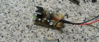
view from the parts
view from the board side.
UPD: 1. Apparently the frequency generator started working after replacing the microcircuit. But the output voltage still does not change - the mosfet is open all the time! I connected an oscilloscope. pulses with an amplitude of 11 volts arrive at the Gate mosfet leg.
The oscillogram shows how the pulse width changes depending on the position of the resistor slider.
Regulator position - minimum feed
Middle position.
Maximum feed.
For some reason the mosfet is not working.
www.drive2.ru
SEMI-AUTOMATIC WELDING MACHINE WITH YOUR HANDSFirst of all, I want to immediately voice one point - this page will be updated as the work done is ready, so if you are interested in the topic, do not forget to bookmark the page, and the next time you visit, click the RENEW PAGE button.
After watching the American movie on aluminum welding, I decided that I also needed such a torch. I didn’t even look for this in local stores, but after visiting a couple of Rostov ones I came to the conclusion that China would help out again.
Of course, the torch with Ali is much smaller and probably less reliable than the one shown in the video, but while you can practice your hands with hooks on a similar toy, especially since the price is not very bad. After some digging in the evening I placed an order. When choosing, I primarily proceeded from the store’s rating, but I also didn’t forget to look at the price. Here the rating is high and it is sent from Russia, although I saw someone a couple of hundred cheaper, but it is sent from China.
Immediately before ordering, I studied reviews about this thing not only from this seller, but also from other traders who had sales of this burner. There are quite a lot of positive reviews about the work, but there are some problems with delivery - the spool holder quite often breaks off during transportation.
My burner was delivered from Russia by a transport company and I, the fool, hoped that during the week of travel they would not have time to break it. We made it…
I won’t lie – in this case I wasn’t even very happy.
Judging by the reviews, the seller is quite adequate, and in such situations I prefer to first communicate with the seller. My plan was to freeze 7-8 dollars from the seller and use this money to buy current collectors for this burner. Current collectors, or tips for such torches, are called on Ali as MIG torch tip Push Pull, so pay attention to the type of tip so as not to buy something unnecessary. RESULTS OF SEARCH TIPS. But let's get back to my problem. I write to the seller that I am upset that the burner is broken and I have photos and videos about this. They don’t have YouTube, so I upload similar stories on my website and provide a link. Those who do not have a website can upload it to Google Disk, not forgetting to open access. But they asked me to send video and photos by email. Necessary? Sent... Then two surprises happened. With the following response, the seller agreed that the product was indeed broken, and a minute later he sent the shipment tracking number - he sent a new burner. This was the first surprise. I don’t seem to need two burners, again it’s not a fact that the burner will not arrive in the same condition. Having digested the information received, a little snidely that now I have a burner for both my left and right hands, I write to the Chinese and say thank you. Then the time came for the second surprise - two weeks later the status of the parcel had not changed - it was awaiting shipment from China. I write to the seller - they say it’s some kind of garbage. He replies that this is normal, we need to wait. Okay, we're waiting. I think to myself - in principle, the burner I received can be repaired, and when there are a couple of hours left before the buyer’s protection closes, I’ll open a dispute and stupidly return all the money, and I’ll give this seller one star rating. By the way, about the seller. Similar torches for semi-automatic welding on Ali are sold in two main types - for a 0.5 kg coil and for a 1 kg coil of wire. Burners with a kilogram coil are a little more expensive, but the coil has a cover that protects it from dust, and this is a significant plus. And it’s easier to buy kilogram coils, at least from us. I repeat - I chose based on the seller’s rating and the point of dispatch, I bought ON THIS PAGE. However, this is not the cheapest option, so you can use the SEARCH RESULTS for MIG welding torch. Then waiting, then more waiting and more waiting...
Well, while the new burner is lying at the border, I decided to take on the task of repairing the miracle that had already been sent. To do this, I fuse wire into the broken area - I don’t throw away the pieces of wire stuck in the Overman - they are often needed for this kind of repair. Next, fabric patches are applied for reinforcement and the whole thing is impregnated with epoxy and smoothed with a soldering iron. Now you don’t have to worry that this tail will break off, but the patches are visible and according to Feng Shui - if you can’t hide it, make it visible. However, I managed to hide it - after a little thought, I blew out the remains of car anti-gravel onto the burner and, in principle, it turned out quite well and this thing became more pleasant to the touch.
WOW! The parcel has moved!
And here it begins to slowly dawn on me how everything happens in reality. They have a huge airship there in Shanghai and they loaded it by hand for a whole month. Having loaded the airship to capacity, it set off. Why an airship? Yes, because the plane cannot fly for 7 days. Then, having arrived in Yekaterinburg, it was unloaded for two days. Here they clearly carried more than one bag, or they used forklifts. After customs clearance, everything went as usual - Podolsk - Rostov - Novoshakhtinsk - Delivery. This time it was packed in a cardboard box, dented, but there were no bends and there was hope that everything was in order. Well, yes - everything is fine. We apply voltage to the engine to check rotation - everything works. Now all that remains is to finish the power supply for this motor and valve, and to resolve the issue with power supply. Well, an afterword. The mechanism of this device is designed to use aluminum welding wire, however, this machine also pulls steel wire quite confidently, although it was necessary to glue porous rubber onto the locking bar - the steel wire is more springy and did not want to lie quietly on the reel.
For those who didn’t understand anything:
We've sorted out the burner, now we'll figure out what to power its engine from. First of all, you need a power supply with an adjustable output voltage, and since there is no power unit for the welding itself, it was decided to try to power the torch motor from a single-cycle forward converter without a demagnetization winding - the so-called oblique bridge. First, you can check the circuitry - if something goes wrong, cheap transistors will burn out, not expensive ones. If everything goes like this, then it will be possible to test the principles of constructing this toy, step on a rake, without worrying about having to rewind large transformers. In general, it was decided to try using the model as a power supply for the pulling mechanism for this burner, i.e. reduced copy. After a little searching on the Internet, it turned out that I didn’t have exactly what I needed. There are quite a lot of circuits that can be adapted to the speed controller of the motor of the broaching mechanism, so after a little thought I did not reinvent a new wheel. Before we talk about the proposed scheme, it is better to READ AN ARTICLE about the controller used, or at least watch a movie:
This is all in order not to write the same thing ten times, but to immediately go to the circuit diagram, because this power supply is very similar to the simplest welding inverter and all the processes in it occur exactly the same as in its powerful brothers . Although there is some rather significant difference - MMA welding inverters are current stabilizers, and to control the motor you need a voltage stabilizer. However, for semi-automatic MIG / MAG welding you also need a voltage stabilizer. So this model is a shot at two birds with one stone.
CLICK ON THE PICTURE - THE DIAGRAM WILL OPEN IN A NEW WINDOW AND IN GOOD QUALITY.
Let's start with the details. L1 is a filter from some kind of computer power supply, taken on a ring because the flexible leads give a little more freedom during installation. VD3 - diode bridge 4...10 amperes. C6 is a must-have film capacitor of 0.47...2.2 µF at 400 volts. C7 - 220...330 µF electrolyte TV1 - control transformer from a computer power supply. The primary has two windings of 40 turns each, the secondary has two windings of 50 turns each. On my copy, all the windings are 40 turns - on the secondary, the voltage is a little too low. Insulation between secondary units is MANDATORY
.
DO NOT WIND THE SECONDARY IN TWO WIRES!!!
TV2 is a control transformer from another computer power supply. The secondary is 200 turns with 0.015 mm wire, the primary is one FULL turn of wire... I wound it with a mounting wire with a cross-section of 0.15 mm. TV3 - in my case this is a TPI core. The turns were counted according to Denisenko’s program. The tap is made on the 5th turn from the top terminal. Resistors R3 and R10 are 5 kOhm, LINEAR. VD14 - Schottky 30A 100 Volt. A few words about C8 - this capacitor is designed to suppress emissions at the moment the control transistor opens and closes. However, it was noticed that in some cases emissions, on the contrary, began to increase. In this case, it is necessary to replace C8 with a resistor from 750 to 1000 Ohms. This power supply was tailored for a specific task, namely to work with an electric motor of a certain power, so it has some shortcomings. Although I wouldn’t call it a flaw, rather it’s a specificity. The fact is that, by definition, the maximum engine speed will not be used, since this is already for welders who were born with a torch. The absence of a maximum duration of the control signal allowed us to throw out several parts, but made this power supply rather specialized. In particular, the gate circuits of power transistors have been simplified to the maximum. If this circuitry will be used as a universal power source, then it is necessary to make some amendments to the circuit diagram, which will be discussed a little later, but for now we’ll deal with the power supply for this feeder. The power supply from the DVD player was initially used as a 15 volt power source, but while all this was being thought about, a board was being developed from China and a baby with 12 volts 0.45 A arrived:
In reality, this power supply is tiny, but its power was enough to power the UC3845 controller and a relay with a 12-volt winding, and it also worked with a relay with 30-amp contacts. I bought the power supply HERE, it took exactly two months, the track was not tracked.
| CLICK ON THE PICTURE - THE DIAGRAM WILL OPEN IN A NEW WINDOW AND IN GOOD QUALITY. |
The diagram shows the resistor values, R8 is the one near the transformer, and not the one near the LED.
By the way, the minimum network range was not found when replacing the resistor - or there is not enough LATR. Why a relay? Well, why? In this case, you also need to open the valve that supplies gas to the welding area. It's like once. Again, no matter how you turn it, when carrying out semi-automatic welding work, you need to turn the wire feed on and off. It is clear that the UC3845 can be stopped by applying a zero to the first pin of the microcircuit - the power will disappear and rotation will disappear. However, I looked through quite a few diagrams of welding machines and one rather interesting point emerged. On semi-automatic machines of medium and high class, the engine is controlled using a relay, and the switch contact is connected to the electric motor. If the motor needs to rotate, the contact closes to voltage supplying the motor. If you need to stop the engine, then this contact switches to the second output of the engine.
For those who do not understand why this is done, I remind you that an electric motor with permanent magnets is reversible, i.e. if voltage is applied to it, the motor shaft will rotate, and if the shaft is rotated, it will output voltage. However, if there is a load on this generator, it will be more difficult to rotate the shaft and the greater the load, the more effort will have to be applied. After removing the supply voltage, the motor shaft will rotate for some time - inertia. However, if you load this generator, then the energy is consumed very quickly. If the leads of the electric motor are connected to each other, which is what happens during shutdown, the motor shaft will stop almost instantly without releasing a single millimeter of excess welding wire. But there is a small BUT...
The more powerful the engine, the more powerful the contacts on the switching relay are needed. That is why a relay with 30 A contacts was used for testing.
Such relays are quite often used for soft start of welding machines, so I took several of them. I bought it HERE. No, no, I didn't forget about the valve. The valve will be rated at 220 volts, and I’m going to turn it on using a 2-amp solid-state relay, so I wouldn’t even call the LED of this relay a load. I bought it two years ago, but after checking the link I discovered that my seller still has them. Got it HERE. But let's return to the power supplies: Surprisingly, both power supplies worked normally at a lower voltage of 160 volts and an upper voltage of 270. I rounded up the range. However, I didn’t have any particular doubts about the big one, but the baby really surprised me. Well, we seem to have figured out the package, a bit of the operating principle: At the moment power is supplied to the controller, it begins to generate control pulses that switch on the control transistor. The control transistor is loaded onto a control transformer, or a galvanic isolation transformer (I’ve also seen that name). The operating principle of this transformer is linear with a demagnetizing winding. There are options for circuits without one, but I decided to use it - a diode is needed anyway, and winding the winding with a double wire takes the same amount of time as with a single wire. The control transformer has two secondary windings, and they form pulses on the gates of the power transistors. After the windings there are diodes VD6, VD7, which cut off the negative voltage after the windings. Next are the load resistors R17 and R18. Load, because this power supply uses transistors with a fairly low gate capacitance, and if you increase the resistance of these resistors, the voltage from the transformer begins to be modulated by shock processes at the moment the control transistor VT2 opens and closes. To suppress this ringing, a capacitor C9 (150...330 pF) is additionally installed. Zener diodes VD8 and VD9 serve to limit the voltage at the gates of power transistors, and for the opening voltage it is 18 volts - the stabilization voltage of the zener diode. And for the closing voltage this is 0.6...0.7 volts - the drop voltage on the zener diode crystal in direct connection. The closing negative voltage passes through resistors R15 and R16. To speed up the closing of power transistors and suppress ringing, snubbers are used on R21-VD10-C9 for the upper arm and R22-VD11-C10 for the lower arm. The power of this power supply is not large, therefore the snubber circuits are not very powerful. Diodes VD12 and VD13 are used to demagnetize the primary winding. In this chain there are HER508, although it is better to use SF56 - they are much faster. I did not install the output snubber R23 and C11 - the ringing in the end was not great, so I decided not to use it. VD14 in my case is 30CPQ100, since similar voltage assemblies for computer power supplies are not suitable. L2, of course, is better to use based on calculations, but I soldered in a ready-made inductance torn from some power supply. I allowed myself such freedom because this power supply will never operate at the power that it is capable of delivering, therefore the probable losses in the inductor are not critical. We return to the moment of power supply - the controller starts to start, i.e. the first control pulse appears. Having passed the control transformer, this pulse opens both power transistors at once and the primary power current begins to flow through the primary windings of the power transformer and the current transformer. Of course, C13 is now discharged and, logically, there seems to be a short circuit, but this is not entirely true - the current cannot reach its maximum value instantly - inductor L2 interferes and the voltage on C13 begins to increase smoothly, thus eliminating the instantaneous value of the charge current. If there is a load at the output of the power supply, then there is still a possibility of reaching a critical value, but this will not happen - if the current exceeds a certain value, the voltage at the output of the current transformer will be sufficient to turn off the control pulse at the current control input - pin 3. Thus, in the first cycle, overload of power transistors is completely eliminated - not only is the current limited by the inductance L2, but the current is also controlled by the current transformer. As soon as the control pulse ends, a negative closing voltage of the power transistors is formed at the output of the control transformer and they, of course, close. The voltage at the output of the power transformer disappears, the remnants of the magnetic field in the core of the power transformer cause the appearance of a self-induction voltage and this voltage is stupidly drained back into the primary power bus through diodes VD12 and VD13. The accumulated electromagnetic energy in inductor L2 is discharged into the load through the lower diode of the diode assembly, and thus, during the absence of voltage at the transformer output, voltage continues to flow into the load. Now here is a rather important point - if it is necessary to obtain high efficiency, then the output inductor L2 should not become saturated at maximum load and maximum duration of voltage pulses from the output transformer. In this way, the inductor can accumulate enough energy so that during a pause there is no voltage dip at the output of the power source. It is for this reason that the output voltage of the power transformer significantly exceeds the voltage that should be at the output of the power source. For example, you can use Denisenko’s program and the calculation clearly shows that if you need to get 24 volts at the output, the amplitude of the output voltage of the power transformer reaches seventy volts:
| CLICK ON THE PICTURE - THE DIAGRAM WILL OPEN IN A NEW WINDOW AND IN GOOD QUALITY. |
And the specified inductance of the output choke should not be less than the calculation showed, otherwise the choke will become saturated and during a pause you will get a voltage dip. And of course, you can use yellow rings from computer power supplies as a core for the inductor, but only if you are prepared for their increased heating. I will not go into great detail why the inductor will heat up, I will just remind you once again that my version of the power supply NEVER
will not operate at powers close to the maximum, therefore heating up to fifty degrees in three hours of continuous operation at the rated load can be considered acceptable.
For those who want to get acquainted with output chokes in more detail, I suggest an article by Sergei Biryukov, editor-in-chief of the Schemotekhnika magazine. READ THE ARTICLE. By the way, Biryukov has quite a lot of interesting articles on switching power supplies, so you can search and get acquainted - your time will be well spent. I got distracted again, so we return to the work of the converter and the time for the second cycle just comes. The output voltage is still growing, and let’s say in the third cycle it reaches the value when the feedback is already starting to work - through resistor R3, the output voltage is supplied to the error amplifier and if the voltage at pin 2 exceeds 2.5 volts, the error amplifier begins to reduce the duration of the control pulses , which entails a decrease in the output voltage. Current regulation in this power supply is organized by forming a bias voltage at pin 3. A sawtooth voltage is formed on transistor VT1, this is purely from the datasheet, but the value of this saw is supplied to pin 3 through a variable resistor R10 from the engine of which this saw is supplied to the current limiting input. But this saw is not supplied in its pure form, but the voltage coming from the current transformer is added to it. If the resistor R10 slider is in the extreme left position, then the saw value from transistor VT1 has a fairly decent amplitude and even a small change in the voltage on the current transformer will already provoke the controller to turn off the control pulse. If the slider of resistor R10 is in the extreme right position, then the influence of the saw from transistor VT1 is no longer very significant and the voltage from the current transformer must reach a fairly large value in order to turn off the control pulse, and for this a decent current is needed. The value of resistor R11 and, of course, R13 determines the maximum value of the current flowing through the power transistors. The main feature of this power source is the control of the current flowing through the power transistors at each conversion cycle, i.e. control is carried out on the instantaneous value, not on the average. WHAT DOES CURRENT CONTROL PROVIDE AT EACH CYCLE? If the current limit is set correctly, this power supply cannot be overloaded. In other words, it does not matter at all according to what laws the load changes and what values it reaches - as soon as the current through the power transistors reaches the set value, the control pulse closes the power transistors. All that remains is to blow the heat out of this power supply and it is essentially indestructible. The voltage is adjusted by an error amplifier - the voltage from the output of the converter is supplied to its input through an adjustable voltage divider R3. Zener diodes VD1 and VD2 limit the voltage at the controller inputs and will not allow the inputs to burn out if something SUDDENLY goes wrong. After assembly, of course, you need to check what was actually soldered, and for this you will need two power supplies. One will remain in this device - it will power the UC3845 controller. The second is temporary, it will simulate the mains voltage. The voltage value of the network voltage simulator is from 20 to 50 volts, optimally 30 volts, this is 10 times less than the primary voltage and you can already draw conclusions about the transformation ratio. This simulation is necessary to check the winding units of this converter - the absence of interturn and the correct phasing of the windings. There is one glitch on the board, so it’s better to read the material to the end - there will be fewer questions.
Of course, using a two-channel oscilloscope for these tests is preferable - much less switching.
However, not everyone has a dual-beam oscilloscope. Therefore, we will perform the test with one beam. Before you start checking, you need to throw a jumper between the negative power supply of the UC3845 and the negative of the primary supply voltage - the lower terminal of C7. Here's a little explanation. There seems to be no problem in winding two secondary coils in the same direction on the control transformer - I opened my little eyes and wound them. But problems may arise with the phasing of the primary - it seemed like I did everything correctly, but in the end it turned out to be out of phase. It is of course possible to desolder the transformer and swap the winding terminals, but it’s lazy. Therefore, the primary winding of the control transformer on the board has a non-traditional layout. The connection point of the half-windings is connected to the second frame terminal from the top, and the outer terminals are connected in ANY order to the third and fourth terminals. The chances of getting the phase correctly are 50/50, but now it is possible to quickly change the phasing of the primary winding by swapping the jumpers:
So, we supply power to the controller and check the presence of control pulses - the ground noise of the oscilloscope on GND UC3845, the measuring probe on pin 6. The frequency of the pulses should be equal to the frequency for which the power transformer was calculated. The next measurement is a measuring probe on the gate of the lower power transistor VT4. If there are control pulses and their shape is close to rectangular, and the amplitude is slightly greater than the supply voltage of the UC3845, then the control transformer is wound correctly and is working, and all that remains is to check the phasing. To do this, place the ground probe of the oscilloscope on gate VT4, and the measuring probe on gate VT2. If you are lucky and everything worked out correctly with the phasing, the screen will show something similar to this:
If you are unlucky and the jumpers under the control transformer are not soldered correctly, then the picture will look like this:
The phasing of the current transformer is checked using the same principle - do not solder R13 during the test, place a load on the output that does not exceed the power of the power supply simulating the mains voltage. However, on the printed circuit board drawing the winding direction is drawn, therefore, by being a little careful, problems with phasing can be avoided. The same applies to winding a power transformer. Before moving on to the printed circuit board, I have a small wish, actually a very small one:
Do not accelerate the conversion frequency above 60 kHz - switching losses will already begin to have an effect quite strongly, and at high currents electromagnetic interference will begin to appear strongly. It is quite difficult to deal with this, and if you are ready to tear your vest because 100 kHz is seeds for you, then be mentally prepared that a gap in the form of a British flag may form between your buttocks. And there is no need to tell me that you did it and everything worked out and worked for you. I say this in all seriousness - an accident is not a pattern. I personally diagnosed the computer that was given to the residents of Novoshakhtinsk in the program “THE DIRECTOR MYSELF.” They won it, therefore it is possible, but this is not a pattern. Printed circuit board in ZIP archive, two-page file. The PRIVOD page is what is shown in the photos and what needs a separate power supply. UNIVER page is a universal version that can be used both as a power supply for the drive and as a regular power supply, since it has self-powering circuits. But at minimum output voltage values, the UNIVER option may turn off because there is not enough power for the controller itself.
In addition, the UNIVER version has holes for several standard sizes of TPI, so there should be no problems installing TPI on the board - I used the most popular standard sizes. Also on the board of the universal version there is an additional track cut - this is the stumbling block that I mentioned earlier. This is necessary to check the current flowing through the transistors - on the side of the printed conductors, a 1 Ohm resistor with a power of 2 W is installed on the cut track. By the voltage drop across this resistor one can judge the current flowing through the power transistors, and of course it is useful for observing changes in the current itself. Of course, you need to look at it with an oscilloscope - the multimeter will show the price of firewood.
After adjusting the output current adjustment range, this resistor is removed and the trace is restored with a drop of solder. What current should be adjusted for? But how do I know what core you will use, what conversion frequency and what power transistors. This is already on your conscience. The only thing I can recommend is to make at least a twofold current reserve for transistors, i.e. if 10 ampere transistors do not need to exceed the maximum current above 5 amperes, or even better 3.3 amperes - as the crystal warms up, the maximum current for field workers drops, and the temperature of the crystal and the temperature of the case are not at all the same thing. Looks like we've sorted out the drive. A few words about the universal power supply and let's go to collective farm controls for the rest of the welding. A universal version of this power supply
operates using self-powering - the start is made using resistor R10, then the controller is powered from the additional winding of the power transformer.
| CLICK ON THE PICTURE - THE DIAGRAM WILL OPEN IN A NEW WINDOW AND IN GOOD QUALITY. |
Now we look carefully at the diagram and try to understand something. We direct our attention to the control circuits of the power transistors. The first thing that catches your eye is that the diodes VD5 and VD6 are turned in the opposite direction. Of course the question arises: WHAT THE FUCK?
Everything is outrageously simple - different transistors are used.
The STP10NM60 has a gate energy of about 19 nC, which is significantly less than even the popular IRF740, which has a minimum gate energy of 43 nC only for transistors from STMicroelectronics
.
For other manufacturers this parameter is at 60nC. The use of lightweight transistors allows for very easy control of them, and in the variant, accelerated opening of power transistors through VD6 and VD7 is used to drive the motor of the broaching mechanism. Closing here is more delayed, since it is done through resistors R15 and R16. A decrease in the closing-opening current of the power transistors ultimately directly affects the consumption of the control module and in this embodiment is minimized so as not to load the circuit breaker that powers the controller and control transformer. The universal version uses transistors with “heavier” SPA20N60 gates, in which the gate energy can reach 114 nC, which is 6 times more than the original version. Naturally, there is no point in delaying opening and closing - the currents will also flow at a greater value. Therefore, on the universal version, R16 and R17 are reduced to 33 Ohms, and the diodes are deployed to ensure faster closing. Also, instead of zener diodes, suppressors are installed in the control, limiting the gate voltage to ±15 volts. In principle, you can use back-to-back zener diodes of 15...18 volts. These elements are necessary to protect the gates from increased voltage - for all transistors, the voltage at the gate reaches ±30 V. For the same SPA20N60, no more than ±20 volts can be supplied to the gate. By the way, in the series of 20 ampere transistors in the TO-220 package there are also “lightweights” with a gate energy of no more than 74 nC. This is FQPF20N60. ATTENTION!
Information for maniacs who buy IRF740 from International Rectifier (
IR
), and then leave their marks in all places where possible:
“The power supply is not working, but the transistors are new, but for some reason they are heating up,”
etc.
The answer is incredibly simple - International Rectifier HAS NOT RELEASED the IR740 FOR A VERY LONG TIME
.
You bought it is not known what, so it works, it is not known how.
This is a screenshot of the result of a request on the website https://www.alldatasheet.com/ - International Rectifier is not listed among the manufacturers of these transistors. But let's return to the power supply. To understand why I am so zealous about gate energy, you will have to read the article about CALCULATIONS OF PULSE POWER SUPPLY SUPPLY IN EXECEL. It mentions what gate energy affects and why it takes precedence over gate capacitance during design. IMPORTANT!!!
The recommended supply voltage for the UC3845 is 12...28 volts. The run up is more than 2 times. I specifically draw attention to this. This fact gives some freedom and at the same time imposes some responsibility when choosing the element base. This applies to control elements for power transistors. First of all, the number of turns of the control transformer. If, according to your idea, the controller will be powered from 12 volts, then it is better to make the transformer step-up - the primary is 40 turns, the secondary is 45-50 turns. You should also pay attention to the voltage limiters in the gates (zener diodes or suppressors - whichever you prefer). If the voltage from the control transformer is greater than the stabilization voltage of this limiter, then the limiter will definitely start to heat up, and you will receive increased consumption of the control module as a whole. If this happens, then you should either reduce the number of turns in the secondary of the control transformer, or replace the voltage limiters with higher-voltage ones. Before replacing zener diodes (suppressors), you need to look at the datasheet for the power transistors used - it indicates what maximum voltage can be supplied to the gates and this value should not be exceeded. In most cases this is ±30 volts, but there are examples with a maximum gate voltage of ±20 volts. If the controller voltage is planned to be within 20...25 volts, then the control transformer must be made step-down, but do not reduce the turns in the secondary, but add turns in the primary. To summarize the above, we will summarize the most important points that need to be taken into account.
| THE CONTROLLER POWER CAN BE 12…28 V. Pay attention to the voltage of the electrolytes set according to the power supply. |
| THE OPTIMUM VALUE OF CONTROL VOLTAGE AT THE GATES OF POWER TRANSISTORS IS 12...18 V. At lower values, with a very short control pulse (idle), the power transistors should receive at least 6 volts to the gates. If they are large, you can damage the transistors. |
| THE VOLTAGE LIMIT AT THE GATES SHOULD BE A COUPLE OF VOLTS MORE THAN THE ACTUAL VOLTAGE FROM THE CONTROL TRANSFORMER. Back-to-back zener diodes or bidirectional suppressors can be used as limiters. |
By the way, here you have the opportunity to play with control pulses and see in what position of the diode and at what value of the resistor there will be the least shock processes on the primary winding of the transformer and the least heating of the power transistors.
Site administration address
prow
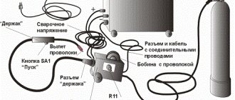
ROTATION SPEED REGULATOR FOR SEMI-AUTOMATIC WELDING ENGINE FEEDING WIRE.
ROTATION SPEED REGULATOR FOR SEMI-AUTOMATIC WELDING ENGINE FEEDING WIRE. Everyone who is involved in the repair of semi-automatic welding machines designed for welding in a carbon dioxide environment during car body work knows that this is the most unreliable component of the welding unit, including industrial machines. A control circuit for the motor of feeding wire into the welding environment using an integrated stabilizer 142EN8B is proposed. The unit must provide a wire feed delay of 1-2 seconds after turning on the gas valve and the fastest possible braking after releasing the welding voltage switch button, which is what this device does.
I would like to draw attention to the cheapest and very effective principle of engine braking by closing the motor armature winding with relay contacts. The disadvantage of this circuit is the rather large power dissipated by the VT1 transistor. The 10X10cm needle radiator heats up to 70 degrees during operation. But in general the circuit turned out to be very reliable.
18.06.09
www.pictele.narod.ru
How to set up a semi-automatic welding machine correctly?
- Date: 06/12/2015
- Rating: 54
Many types of welding equipment are expensive. The most convenient is a semi-automatic welding machine (SPA), which is multifunctional. The operating principle of a semi-automatic welding machine depends on its correct settings. Semi-automatic welding machines are universal and practical. Their use in the domestic economy is widespread.
Scheme of an inverter semi-automatic welding machine.
In everyday life and industry, SPA is used to produce effective welding. Performing welding work using semi-automatic machines is based on high-quality welding of non-ferrous and ferrous metals without the use of additional elements. The welding process uses carbon dioxide or argon, which are protected by the use of a melting type of solid wire.
What are the requirements for the preliminary welding stage?
Basic semi-automatic welding modes.
Powerful welding equipment should be used while observing safety precautions. The spa is dangerous because it can cause electric shock. Incorrect use of the equipment may result in fire.
Incorrect configuration of a semi-automatic machine can lead to damage to some parts of its design. All of these preliminary steps must precede mechanized welding using this device. The idle mode of operation of the spa should not be associated with the delivery of voltage to the tip of the hose.
Before starting work, the grounded terminal is connected to the SPA. Then you should adjust the power parameters, as well as the welding wire feed speed. Setting options are provided according to the thickness and type of metal. There are tables indicating all welding parameters using SPA. They can be found in specialized literature describing the welding process.
List of possible malfunctions of the welding inverter.
Setting up the SPA involves mandatory monitoring of the voltage on the welding wire, that is, the electrode. The control process of a semi-automatic device assumes appropriate logic based on the following circuit for removing and supplying voltage to the SPA:
- Removal from microswitch.
- Engine supply.
- It flows to the reverse winding of the motor.
- Receiving it with a sleeve and gas cutoff.
Having studied all the safety requirements and special instructions in books, they proceed to working with a semi-automatic device. First, you should connect it to the electrical network and press the power button. The trigger of the device should be pressed when the face is protected by a special mask.
First you need to cut off the excess wire, leaving about 3 mm, counting from the end of the burner. After the arc appears, you should slowly move the torch to the future connection. When lumps form on the end of the wire, it is necessary to increase the wire feed speed into the apparatus.
How to set up a semi-automatic machine for high-quality gas supply?
Inverter front panel diagram
You can adjust the dosage of the amount of inert or carbon dioxide coming from a gas cylinder or reducer automatically or manually. With the correct settings of the semi-automatic welding machine, the electric arc will burn perfectly evenly. This allows the welding process to be carried out virtually without splashes.
It is necessary to ensure that the metal of the connection does not boil. This is achieved by correctly setting up the semi-automatic welding machine by ear. The gas hisses quietly during welding, producing a uniform noise.
An experienced welder ensures that the gas is blown and not blown. In this case, the arc should not break, so you need to move the wire forward. If intermittent hissing sounds occur and the wire melts rapidly, which occurs faster than the burner moves, it is necessary to reduce the feed speed.
Sometimes it is necessary to adjust all the settings for high-quality welding for several days until an even, stable arc is obtained.
It has a stable sound and a characteristic crackling sound. The type and amount of gas supplied plays an important role in the process of regulating the welding machine. For example, a porous and weak weld will result from insufficient gas flow.
What semi-automatic devices allow you to make adjustments?
Image 1. Schematic diagram of the SPA.
The operation of any spa is associated with the presence of a welding transformer in its design. The susceptibility of welding current switches to wear requires the constant participation of a master regulating the welding process. For this purpose, you can use a contactless relay, which is the switching board of the transformer device. This is due to the presence of a significant resource in terms of switching.
The adjustment process is based on the use of an electrical signal transmitted through a circuit (IMAGE 1). The semi-automatic control system has an action logic that allows blocking the switching of each stage of the transformer device during a welding load. However, this can be a common reason associated with broken switches.
The simplest device that allows you to customize the SPA circuit is a throttle. It has several stages, which can be switched when the inductance level decreases or increases. Another possible device for adjusting the device is an active throttle.
Power supply circuit for a semi-automatic welding machine.
When using this device, you will not need to use mechanical switching, which will ensure smooth adjustment of inductance parameters. This adjustment mechanism allows you to correctly configure the process associated with the transfer of materials.
Manual arc welding, which allows connections to be made using a welding inverter, is also typical for semi-automatic machines. Therefore, an important PV parameter is provided for it. It is a percentage designation showing the permissible operating time of the semi-automatic device. This indicator will allow you to maintain the level of wear resistance of the equipment for a long time, ensuring its operation at a high-quality level.
Before using the semi-automatic device, the current value must be adjusted so that the metal does not become burnt. However, determining the exact current value is difficult. This point requires, before starting welding, to carry out training using a metal plate into which the wire is inserted. You can change the welding current using a rheostat. This is the most effective means of adjusting the welding arc for different metal thicknesses.
Recommendations for correctly setting up a semi-automatic welding machine
Semi-automatic welding process.
The welding current indicator should be set in the settings depending on the thickness of the metal being welded and the diameter of the wire used as an electrode. This dependence is relatively standard, so the value of the indicator does not fluctuate much.
Typically, the device body or its instructions should contain information about the possible values of the welding current indicator. In certain cases, the table with indicators may be missing for some reason. Then experts recommend using the following current indicators for welding metal, taking into account its thickness, indicated in brackets:
- 20 - 50 A (1-1.5 mm).
- 25 - 100 A (2-3 mm).
- 70 - 140 A (4-5 mm).
- 100 - 190 A (6-8 mm).
- 140-230 A (9-10 mm).
- 170 - 280 A (11-15 mm).
Torch for semi-automatic welding with a consumable electrode: 1 - mouthpiece, 2 - replaceable tip, 3 - electrode wire, 4 - nozzle.
This list is associated with a fairly large range of indicators that are united by a common trend. Its principle boils down to the fact that to weld the thickest material, a greater welding current is required. This indicator is determined by the diameter of the wire used.
If you use thin wire during the welding process, it allows you to configure the semi-automatic machine to operate using less current. If you use thicker welding wire, more current will be required. Due to the inertia of mechanics, the movement of the welding wire occurs slowly, gradually accelerating.
You can regulate the motor current using a special switch. The welding current must be sufficient to ensure complete braking of the wire. The current is adjusted in the semi-automatic welding machine using a trimming rheostat. Subsequent braking of the wire occurs after a certain time.
What results can you get from setting up a spa?
Submerged arc welding diagram.
As a result of the adjustments made, the welding wire should not spread or melt. This occurs when a very small current value is selected. You will need to increase the voltage to check the result. If the wire has spread well, then a “drop” should appear on the back of the metal. This will mean that everything is normal.
If, after using the welding wire, a slight depression is formed, then the “drop” will hang on the other side. This is due to the choice of the welding current value above the norm. You should take another piece of metal to conduct the experiment at a lower voltage level.
If a hole appears instead of a wire, then this is due to the choice of too high a current value. You should use another workpiece to carry out semi-automatic welding at a lower voltage level. For training welding, workpieces coated with zinc cannot be used, since it evaporates and releases harmful substances. They can harm the human body.
https://moyasvarka.ru/youtu.be/gsBDcZWozYE
After preliminary training, you should finally make sure that the current settings are correct. In this case, the metal workpiece must be clamped with sufficient force. Only after this can you proceed to the main welding, not forgetting about safety precautions. Before welding, you should be dressed in a welder’s suit and protect your face with a special mask.
moyasvarka.ru
Do-it-yourself semi-automatic welding machine: how to make it, diagram and all the details
A unit designed for welding products is considered to be a semi-automatic welding machine. Such devices can come in various types and shapes. But the most important thing is the inverter mechanism.
It is necessary that it be of high quality, multifunctional and safe for the consumer. Most professional welders do not trust Chinese products and make the devices themselves.
The manufacturing scheme for homemade inverters is quite simple. It is important to consider for what purposes the device will be manufactured.
There are inverters for:
- Welding using flux-cored wire;
- Welding with various gases;
- Welding under a thick layer of flux;
Sometimes, to achieve a high-quality result and obtain an even weld, the interaction of two devices is necessary.
Inverter devices are also divided into:
- Single-hull;
- Double-hull;
- Pushing;
- Pulling;
- Stationary;
- Mobile, which includes a trolley;
- Portable;
- Designed for beginner welders;
- Designed for semi-professional welders;
- Designed for professional craftsmen;
Inverter circuit:
Principle of operation
The operating principle of the inverter includes:
- Adjusting and moving the burner;
- Control and monitoring of the welding process;
When the unit is connected to the electrical network, a conversion of alternating current to direct current is observed. For this procedure you will need an electronic module, special rectifiers and a high-frequency transformer.
For high-quality welding, it is necessary that the future unit has parameters such as the feed speed of the special wire, current strength and voltage in identical balance. For these characteristics, you will need an arc power source that has current-voltage readings.
The length of the arc must be determined by the specified voltage. The wire feed speed directly depends on the welding current.
Homemade device diagram:
The electrical circuit of the device provides for the fact that the type of welding greatly influences the progressive performance of the devices as a whole.
Electrical diagram of a homemade device:
DIY semi-automatic - detailed video
Created plan
Any scheme of a homemade device provides a separate sequence of operation: