The principle of operation of the chain hoist
A rope/chain is thrown through a static pulley to lift the load; the load is lifted by applying forces comparable to the original weight.
A chain is passed through this structure. The height to which the load is lifted must be equal to the length of the rope. This scheme does not allow reducing either the power or speed indicators of the process of moving cargo. It is possible to halve the effort required when using a lifting mechanism; the end of the rope fixes the system on a static pulley, and a special movable roller and hook are suspended from the load. In this case, the movable pulley of the mechanism moves parallel to the load and the effort required to lift it is reduced. The operation of such a lifting device is based on these simple manipulations.
The main task of fixed blocks is to create a path for the rope/rope to move, preventing the effort required from being reduced. Movable pulleys, when attached to a load, can benefit from effort. You can halve the effort required to lift a load by increasing the composition of the design system into paired pulleys, consisting of a movable and a static pulley, based on the number of movable rollers.
Reservation - chain hoist
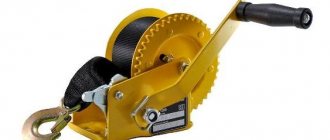
| Rope testing stand.| A device for determining the mass of a load. |
Refilling chain hoists is performed as follows. An auxiliary rope with a diameter of 6 mm is manually stored in the blocks. One end of the auxiliary rope is connected to the winch, and the other to the main rope.
Refilling of pulley blocks is carried out without twisting the ropes or distorting the lower blocks. The pulleys are loaded evenly at low speed.
Refilling of pulleys and their subsequent loading is carried out without twisting the cables or distorting the lower blocks. The pulleys are loaded evenly at low speed. Before work, check the serviceability and reliability of the brakes and safe jack handles, the integrity of the frames, support heads and lower legs. To increase the supporting surface, rack and screw jacks are installed with spacers, and sleepers and sleeper cages are placed under hydraulic jacks. Gaskets and cages are placed perpendicular to the jack axis, which must coincide with the direction of movement of the structures or apparatus. Release of jacks from under a raised load and their rearrangement are allowed only after the load has been securely secured in the raised position.
The chain hoist is refilled in two ways. According to the first method, used when equipping multi-thread pulleys with a large load capacity, a stationary block without ropes is lifted into the working position and secured; the lower moving block is at the bottom. Then the rope is passed sequentially through the streams (grooves) of the rollers of the upper and lower blocks.
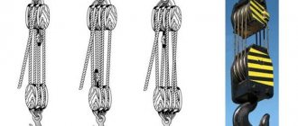
Reeving schemes for pulley hoists are shown in Fig.
The reeving scheme for the cable pulleys, the load capacity, the number of rollers in the blocks, the number of working threads of the pulleys, the type of winches, their rope capacity and traction force, the length of the cables, pulleys, and the load capacity of the anchors are assigned according to the load size and the pulley diagram.
A chain hoist is stored, consisting of two single-roll, double-roll or triple-roll blocks, depending on the mass of the rolls. One of them (movable) is attached to the boom head, the other (fixed) is attached to the hook of a tractor winch or anchor.
- Lifting loads without special equipment
A chain hoist is stored, consisting of two single-roll, double-roll or triple-roll blocks, depending on the mass of the rolls. One of them (movable) is attached to the boom head, the other (fixed) is attached to the hook of a tractor winch or anchor. The roll slinging rope is attached to the boom head. A rope from an insurance (braking) tractor is attached to it, with the help of which the boom, after securing all the ropes, is brought out until it rests on the roll. After this, the insurance rope is reattached to the top of the roll, the ring sling is brought under the top of the roll (at a distance of 400 mm from the top), fittings are placed in the loops of the sling, onto which the roll slinging rope is put. Then the winch, selecting the chain hoist thread, brings the boom to the vertical. When the boom reaches 70 - 75, the sling and ring ropes should tightly wrap around the roll, creating a sling-noose through the fittings.
| Beginning of installation of tower crane V K. - 1000. |
The tower lifting chain hoist is reloaded, the assembled part of the tower is lifted using assembly winches, and then the next two sections of the tower are installed.
| Single roll block. |
Reeving pulleys using an additional upper outlet block is often found (Fig. 110, a), which makes it possible to increase the load capacity of the pulley and reduce the force in the running thread. If, when lifting a load, the pulley is long or has many threads, the reeled rope may not fit on the winch drum.
| Scheme of reeving pulleys with different numbers of working threads.| Schemes for storing chain hoists. |
Reeving pulleys using an additional upper outlet block is often found (Fig. 86, a), which makes it possible to increase the load capacity of the pulley and reduce the force in the running thread.
Rules for reeving ropes - KRAN.PRO
Depending on the traction force and the multiplicity of the installation chain hoist, various schemes for storing ropes in the chain hoist are used. In practice, a simpler spiral reeving scheme has become widespread, in which the branches of the rope in the pulley are parallel to each other. In this case, the stationary branch of the rope is applied to the cheek of the clip next to the first rope block,
In the absence of mounting clips of the required traction force, two single pulleys operating together are used, driven by one or two traction winches. According to the first scheme, the fixed branch of the rope is attached to the movable holder of the left pulley, and according to the second scheme there is no fixed branch and both branches are directed to the drums of the traction winches. The presence of an equalizing block for the tension of the rope branches of both pulleys is mandatory.
At the same time, in practice, they do not attach importance to the direction of reeving the rope into the pulley block. However, it should be remembered that the rope in the pulley when moving from one rope block to another bends and deviates from the plane of the block. Bending of the rope is accompanied by rotation (displacement) of its cross sections and leads to the occurrence of torsion of the rope relative to the longitudinal axis. In this case, the combination of directions of laying of rope elements and its bending turns out to be important. Thus, depending on the combination of these directions, the twist angle of the strands in the rope can increase during bending (the rope twists), which has a positive effect on its structural integrity, aggregate strength and service life, but increases its flexural rigidity. Otherwise, the angle of lay of the strands decreases (the rope unwinds), which causes a weakening of the bonds between the elements of the rope, a decrease in its aggregate strength and causes the occurrence of various structural defects, for example, “lanterns”, “bugs”.
Undesirable additional torsion of the rope under load not only complicates the operation of the pulley and causes accelerated wear of the rope, but also causes twisting of the pulley, which is especially dangerous for long multi-branch rope systems. However, this phenomenon can be controlled.
The behavior of a rope during bending can be traced using a simple experiment performed by the author. Right lay rope of 6X19+1 o design. With. with a diameter of 5.6 mm according to GOST 2688 - 80, it is possible to freely manually bend it into a coil with a diameter of 45...50 mm (the ratio of the diameters of the circle of the coil and the rope is D/dK = 10), running from right to left. In this case, the rope is twisted and the pictures are hidden in the direction, which is registered organoleptically (felt by the experimenter’s fingers). The same rope can barely be bent into a thread with a diameter of up to 300 mm (diameter ratio D/dK> >50) in the opposite direction - from left to right. In this case, a significant internal structural torque arises in the rope, which is even more clearly felt by the experimenter’s fingers. The specified torque causes the rope to unwind and actively prevents its bending, as a result of which, when the thread is tightened (reducing its diameter), the latter comes out of the plane and diverges.
Therefore, when selecting the design of a steel rope for pulleys, it is necessary to give preference to low-twisting steel ropes and use rational spiral reeving schemes that provide additional twisting of the ropes during operation. So, in the case of reeving right lay ropes into a single pulley block, it is necessary to ensure the direction of the turns from right to left, and for left lay ropes - from left to right. When storing ropes in double pulley blocks, in which the rope changes the direction of bending on the equalizing block, this requirement turns out to be insignificant.
Spiral reeving of the rope into the pulley block, due to the uneven tension of the individual branches of the rope in it, does not ensure parallelism of the axes of the mounting clips (causes their distortion) during operation. At the same time, deviation angles increase with all the undesirable consequences. To eliminate these shortcomings, a cross rope reeving scheme is used, which practically eliminates the misalignment of the axes of the clips and the twisting of the mounting pulleys.
In cases where the design of the cage provides for the possibility of attaching a stationary branch of the rope in the middle of the cage, a reeving scheme is used in which the movable branch of the rope comes off the middle rope block. In this case, the direction of the rope lay does not affect the performance of the pulley and is not taken into account.
The rope is loaded into the assembly pulley by a team of riggers who are trained in the methods of performing the work, who know the sequence of technological operations and the rules of personal safety, and who are provided with working tools, adapted and necessary materials.
There are two ways of reeving a rope in vertical and horizontal positions of the pulley. According to the first method, the stationary clip is suspended from the structure, and the movable clip is placed on a wooden shield or sled on the ground. In this case, the rope reeving is performed at height, which is more labor-intensive and unsafe. According to the second method, both clips are placed horizontally on the shields. It is advisable to use a special stand designed by Giproneftspetsmontazh. Recommended distances between mounting clips with a force of up to 1000 kN are 1.5...2 m; up to 2800 kN - 2...3 m and up to 6300 kN - 5...6 m.
When reeving large-diameter ropes, you should use a more flexible auxiliary steel rope with a diameter of 5...8 mm or hemp rope, called lightweight. The auxiliary rope is manually inserted into the rope blocks of the clips in accordance with the accepted reeving scheme. One end of the rope is connected to the main rope of the pulley using a special U-shaped clamp or braid (knot), and the other is attached to the winch drum. By turning on the winch, the main rope is retracted into the pulley block. At the same time, special attention is paid to connecting the ends of the ropes through the streams of the rope blocks.
The speed of the ropes should be minimal. After reeving the rope into the pulley clips, the rope is disconnected, the stationary branch of the rope is attached to the mounting clip, and the movable branch is attached to the traction winch drum.
kran.pro
Levers and blocks | Strength and movement
Levers and pulleys are simple mechanisms. A lever consists of a rod and a point of fulcrum or rotation. The pulleys use a rope secured in the wheel groove.
If you apply a force to one end of a lever, then a force also arises at the other end. A lever can be used to gain strength - the force acting on the load can be significantly greater than that applied to the other end of the lever. In particular, with the help of a crowbar, used as a lever, it is possible to move huge boulders that cannot be lifted manually.
To increase the force, a system with two or more blocks is sometimes used. Not only do pulley systems provide gains in strength, but they also make it possible to change the direction of the force applied to the rope.
LEVERS
The lever rotates around a fixed point called the fulcrum or axis of rotation. The distance between the fulcrum and the place where the force is applied and where the load is placed determines how many times the force can be gained. Using a coin as a lever, you can open a can of paint. To do this, one end of the coin must be pushed into the gap between the lid and the jar, and the rim of the jar will act as a fulcrum. Now, by pressing the coin on the other side, you can lift the tightly inserted lid. If you don’t have enough strength to open the jar with a coin, you can use the handle of a spoon. Its free end is placed further from the fulcrum, and a significantly greater force will be applied to the lid from the second end.
DIY block system for lifting loads
SINGLE BLOCKS
The block is a wheel with a groove that rotates around an axis. A rope is fixed in the gutter. By pulling one end of the rope, they lift the load attached to the other end. When using a single immovable block, the traction force is equal to the gravity of the load. So, a single stationary block does not provide a gain in strength. The direction of the force that moves the load is different from the direction of the traction force.
CHALLENGES
You can make two blocks work simultaneously if the axis of one of them is secured to a high support, such as a beam, and a load is suspended from the axis of the second. One end of the rope is attached to the axis of the immovable block. If you pull the free end of the rope, the load will begin to rise. Systems of several movable and fixed blocks are called pulley blocks.
A pulley with 2 pairs of blocks gives a 4-fold increase in strength. The distance over which the rope is pulled is 4 times the height to which the load is raised. To lift very heavy loads, cranes and other lifting mechanisms are equipped with chain hoists with several pairs of blocks.
Using a double block reduces the force required to lift a load by half, that is, by applying a force of 100 N to the rope, you can lift a load with a gravity force of 200 N. Thus, a double block gives a double gain in strength; in this case, to move the load 1 m, you have to choose 2 m of rope. Since the work is equal to the product of the acting force and the distance, the work done is 100 N x 2 m = 200 J, and it is equal to the work done in lifting the load 200 N x 1 m = 200 J. In general, the gain in force is equal to the number of blocks.
1.Transportation and storage of ropes.
1.1. When delivering a rope to a storage or hanging site, the drum must be removed from the vehicle using lifting mechanisms in such a way as to prevent damage to the rope and drum. It is prohibited to drop the drum with rope from the vehicle or remove it in ways that lead to its damage or disruption of the layer of conservation lubricant.
1.2. Ropes received for storage must be inspected; Lubricate the sections of the rope exposed during transportation and loading and unloading operations with rope lubricant. The lubricant must be compatible with the type of lubricant applied during rope manufacture. Measure the diameter of the rope.
1.3. During long-term storage, ropes must be inspected along the outer layer and lubricated at least after 6 months.
1.4. Ropes must be stored in ventilated areas or under a canopy in conditions that exclude precipitation, away from vapors and corrosive atmospheres. The axis of the drum must be parallel to the floor on which the drum is installed. Drums should not be placed directly on the ground. They must be installed on special floorings, support beams or racks.
Description and design of pulleys
The design itself is a device for lifting loads using special connection blocks and ropes between them. Using the rule of leverage and friction, the structure comes into action increasing the force or speed of lifting the object. There are different types of pulleys, which differ in the number of blocks, rope connections, load capacity and other configurations.
The system, in turn, consists of movable and fixed elements along which ropes are installed, creating tension and ensuring the transportation of cargo. The fixed element is the main structure that is attached to the equipment or static bar, and the movable element is attached to the load. Therefore, the first must be able to withstand high pressure, and the second must distribute it evenly.
Block system
The lower or moving block is usually equipped with a special fastening, in the form of a hook, a powerful magnet, a carabiner, and so on. The upper block has special rollers along which the rope is passed, and the pressure exerted on each rope individually depends on the number of rollers. This means that lifting large heavy loads requires an appropriate number of rollers and working branches.
The video explains and demonstrates how the chain hoist works, and also reveals its advantages
Device
A simple chain hoist consists of two pulleys connected by a rope, cable, or chain. The pulley is made in the form of a metal wheel rotating on an axis. A groove is made along the outer edge for laying the cable. The pulleys that make up the structure are called blocks. Some of them are fixed stationary, others change position as the load moves. Movable blocks are placed on the side of gravity. The fixed block changes the direction of movement of the cable and the vector of force application, while the moving ones increase the force applied to the load. The movement of the load occurs due to the fact that it is pulled through a system of blocks by a rope to the fixed part of the pulley.
Simplifying device assembly
At home, you can use improvised materials and ready-made transfer units. For example, the ratchet used in a KAMAZ vehicle to equalize the braking force is a ready-made worm gear mechanism.
By combining block mechanisms with drum winches, you can work to compensate for the shortcomings of each type of lift. For example, pulley hoists do not provide a lock that prevents reverse movement of the hoist, but drum swans eliminate this very simply. But the angle between the lifting force vector and the weight vector of the pulley can be almost anything, which winches cannot boast of.
Reeving - cargo rope
Rewinding the cargo rope in this case allows you to move the load when the horizontal reach changes.
The simplest reeving of a cargo rope is shown in Fig. 36, g. The hook is suspended on one thread of rope 2, which passes through the blocks of the jib, boom, tower struts and is wound on the drum 1 of the cargo winch
The inconvenience of this scheme is that when the reach changes, the load rises or falls along with the boom, and when installing buildings from large elements, it is important that when the reach changes, the load moves horizontally. Therefore, modern luffing jib cranes use a system of connected pulleys.
The reeving diagram of the cargo rope is shown in Fig.
After re-reeving the cargo ropes and installing a new section on the mounting rack, this one is lifted and installed. Having finished building the mast, they lift the head to its top using a manual winch, re-pass the cargo ropes and the speed limiter rope, install guides (rules for turning off the limit switches on the floors), check the lift and safety devices.
| The simplest rope pulleys. |
The cargo rope is used to lift the hook suspension. The simplest reeving of the cargo rope is shown in Fig. 36, a. The load is suspended on two strands of rope, with one end of the rope secured to the boom head, and the other passing through the boom and head unit, and then wound onto the cargo winch drum. With such a reeving, the winch should develop a force slightly greater than half the weight of the load
The inconvenience of this scheme is that when the reach changes, the load rises or falls along with the boom, and when installing buildings from large elements, it is important that when the reach changes, the load moves horizontally.
| Hook pendants. |
Single- and biaxial suspensions are used on cranes with double-thread reeving of the cargo rope. For greater load capacity with a four-thread reeving, three-axle suspensions are installed. The latter allow you to change the reeving ratio of the rope depending on the weight of the load being lifted. It rises up and is held on the boom head by a cargo rope due to the mass of the hook suspension, which in this case works similarly to a biaxial suspension. For heavy loads, the suspension is lowered to the ground and the clip 4 is lowered down. After connecting the clip to the suspension cheeks, four threads of rope are involved in the work.
| Boom equipment of the K-46 crane with rigid curved. |
In addition, equipment with an extended boom is distinguished by the fact that the reeving of the cargo rope 2 is changed in accordance with the load-carrying capacity of the machine with an extended boom, a longer stretch 3 of the pulley block 4 of the boom lift is installed, as well as its own indicator 5 of the extension of the boom. On some cranes (KS-2561D) an extended rope of the jib pulley is installed.
| Rope reeving schemes. |
On the head section of the boom there is an axis of blocks and a bracket for attaching a thimble or installing an additional block when changing the reeving ratio of the cargo rope.
| Kinematic diagram of the mechanisms of the MSK-5-20 crane. |
Refilling the cargo rope on the drum of the cargo and boom winches ensures horizontal movement of the load when the boom radius changes, which is convenient in operation and allows you to reduce the power spent on lifting the boom.
| Lift Height Charts.| Refilling the ropes of the KB-160 crane. 4. |
Reeving - rope - Great Encyclopedia of Oil and Gas, article, page 1
Reeving - rope
Page 1
The reeving of the ropes of this crane is somewhat different from the reeving of the ropes of the previously discussed cranes. [2]
The rope retrieval is shown in Fig. 122, a: one end of the boom rope 1 is attached to the boom winch drum, the other is pulled through block 2 of the superstructure, blocks of the fourteen-fold pulley 3 and is fixed in thimble 4 located on the superstructure. [4]
Refilling of ropes is shown in Fig. [5]
Refilling ropes is a system of ropes with a diameter of 24-13 and 4-8 mm, with the help of which the frame of the working body is raised and lowered. [6]
Retention of winch ropes is carried out through blocks, one of which is suspended from the building structure, and the other from the boom head. The installation winch is installed in such a way that the traction cable does not interfere with the installation of the crane elements. [8]
Such rope reeving ensures a double pulley system with triple pulleys, which has greater resistance to twisting relative to the vertical axis. At the edges of the traverse, brackets can be installed for hanging slings on them. A load-handling device, for example a motorized scaffolding grab, is connected to the trunnion by a lock. [10]
The refilling of the closure rope is such that after the jaws are closed and the tree is grabbed at the butt, when the hoist drum rotates, the grab is lifted. Then the trolley movement mechanism is automatically turned on. When approaching the unloading site, the cart stops automatically (from the limit switch), the grab opens and the tree is unloaded, then the movement mechanism is turned on and the cart returns to its original position. The lowering of the open grab to grab the next tree also occurs automatically after the trolley stops. [eleven]
Refilling of heavy ropes is carried out using a rope of small diameter. [13]
Rewinding the ropes of multi-strand pulleys for lifting heavy loads is carried out using winches, hoists or a light auxiliary rope (5-6 mm in diameter), which is passed manually through the rollers of the blocks, with one end attached to the end of the main rope, and the other on the winch drum . [15]
Pages: 1 2 3 4 5
www.ngpedia.ru
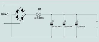
Chain hoist diagram
Here is the simplest diagram of a chain hoist.
Circles are blocks. A large circle drive, or rather a drum. The end of the cable is not fixed to the crane hook, but to a surface that is stationary relative to the crane. Such a surface can be a crane boom or, if we talk about tower cranes, a carriage. The lower block is not fixed to the crane in any way and is movable relative to it. These are the two simplest schemes for constructing a chain hoist.
What loads arise in this case?
Calculation of the chain hoist
It would be more correct to ask how the load on the engine and on the rope itself will change. In our case, it will decrease by half. Of course, you can cite formulas and school examples known since the time of Archimedes, but you can take my word for it. But this is a relatively simple example. I will tell you more complex ones in another article. Now let’s look at what types of chain hoists there are.
Purpose and use of the chain hoist
In modern construction, pulley blocks are used very widely. The crane hooks of a complex design with jaws are immediately designed for them.
The pulley design can be blocked if it is not necessary. The use of a chain hoist as an independent hydraulic lifting mechanism is limited by only one factor - the lack of a brake, which is vital in lifting machines.
Many specialized companies sell chain hoists. Before buying a chain hoist, make sure that the selected characteristics are correct for your needs and if in doubt, contact a professional.
Types of pulleys
Pulley hoists are divided according to several criteria:
- By appointment.
There are power schemes, and there are speed schemes. Power lifts allow you to lift more weight, but more slowly. High-speed ones allow you to lift weights faster, but will “handle” less weight. - By the number of blocks.
The simplest option is 1 video. But there can be 2, or 3, or 4, or more. The more there are, the more weight you can lift. - According to the complexity of the scheme.
There are simple schemes (when the rollers are connected in series by 1 rope) and complex ones (when 2 or more separate pulleys are used). Complex systems are more productive, producing more results with fewer blocks. For example, if you combine 2 pulleys (from 1 and from 2 blocks) you will get a 6-fold gain in strength. Whereas a simple scheme will give a 6-fold win only when using 6 rollers.
What affects the efficiency of a lift?
The multiplicity mentioned above (gain in strength) is very approximate, rounded up. In practice it is less.
The effectiveness of the lift (what exact gain in strength it will give) is influenced by the following factors:
- number of blocks;
- cable material;
- bearing type;
- quality of lubrication of all axes;
- rope diameter and length;
- the angle between the rope and the middle plane of the roller.
How is the rope attached to the mechanism?
You can attach the lifting mechanism to the cable in the following ways:
- Knots connected from cords. Number of revolutions - 3-5.
- General purpose clamp.
Performance characteristics of chain hoists and their selection
The effectiveness of pulley blocks, their purpose and design in a particular mechanism are influenced by the following factors:
- Load capacity of the main mechanism in which these units operate.
- Number of bypass blocks: as their number increases, friction losses increase.
- Deflection angles of ropes from the middle plane of the drum.
- Block diameters.
- Rope diameter/chain height.
- Rope material.
- The nature of the supports (in rolling or sliding bearings).
- Conditions for lubrication of all axes of the pulley block.
- Speed of rotation of blocks or movement of traction ropes (depending on the purpose of the device).
The greatest losses in pulleys are associated with friction conditions. In particular, the efficiency of the mechanisms under consideration, which operate in sliding bearings, depending on their operating conditions, is:
- With unsatisfactory lubrication and at elevated temperatures - 0.94...0.54;
- With rare lubrication - 0.95...0.60;
- With periodic lubrication - 0.96...0.67;
- With automatic lubrication - 0.97...0.74.
Smaller values correspond to pulleys with the highest possible multiplicity. Friction losses for units that operate in rolling bearings are much lower and amount to:
- With insufficient lubrication and high operating temperatures - 0.99...0.83;
- At normal operating temperatures and lubrication - 1.0...0.92.
Thus, by using modern antifriction coatings on the contact surface of blocks, friction losses can be virtually eliminated.
The angles of deflection of the rope located on the pulley block/blocks determine not only the wear of the ropes and blocks, but also the safety of the production personnel of the lifting device. This is explained by the fact that if the permissible values are exceeded, the rope coming off the block is fraught with an industrial accident. This parameter is influenced by the material of the ropes, the profile of the drum groove, as well as the direction of winding.
The most common types of rope materials are TLK-O according to GOST 3079, LK-R according to GOST 2688 and TK according to GOST 3071. The third type has the lowest rigidity (no more than 1.7), which has a positive effect on the maximum permissible angle of deflection of the rope on the pulley. Accordingly, for the first two types of ropes, the stiffness reaches 2.
Normal angles of deviation from the pulley axis are considered to be angles of 7.5...2.50 (smaller values are accepted for maximum ratios of the block diameter to the rope diameter). In general, when designing these devices, they always try to choose this ratio in the range of values 12...40. The permissible angle of deflection of ropes made of low-rigid materials is less: up to 6.5...20.
GOST allows an increase in the maximum deviation, compared to the recommended one, by no more than 10...20% (depending on the operating mode of the lifting equipment). On the equalizing block, the permissible deviation angles can increase, but not more than 1.5 times.
To reduce the deflection angles, profile grooves are made on the pulley drums, and the angle of their direction depends on the winding direction. Therefore, drums in mechanisms of modern design are always made with a cross profile, suitable for both types of winding.
Simple models
The simplest chain hoist can be built from a single block.
Based on the school physics course, we know that when lifting a load in this way, the necessary force required to apply to the free end of the rope will be half the weight of the load. In this case, the length of the rope selected during the lift will be twice as long as the height to which the load will rise. Such a simple lifting device can, in principle, be called a 2:1 chain hoist, i.e. a device that doubles the applied force. When lifting a load in this way, you can do without a block at all, using a regular carabiner instead.
With two blocks we can increase our strength by 3 times. In this design, using two gripping knots that are tightened when the rope is pulled, we additionally provide insurance against falling of the load in case the chooser unexpectedly releases the rope.
By adding a couple of blocks to the first structure, we get a theoretical gain in the force applied to the load by 4 times, losing the same amount in the length of the rope. This is already a 4:1 chain hoist. Where does the extra strength come from? With this load suspension scheme, 3/4 of its weight falls on the support, and only 1/4 loads the free end of the rope. “Give me a fulcrum and I will move the earth,” Archimedes reasoned on the topic of levers and pulleys. It would seem that by analogy increasing the number of blocks used, we can theoretically increase our capabilities in lifting loads to infinity. However, practice turns out to be more cruel, because there is still friction in the world. The best blocks used in practice take up at least 10% of friction. Thus, applying sufficient force to lift a load of 1 kg. according to the first scheme, we will be able to overcome a load of 2*0.9=1.8 kg, and when using a 4:1 chain hoist, not 4 kg, as expected, but 4*0.9*0.9*0.9=2.91, i.e. the gain will be less than 3 times , with rope losses of 4! When using carabiners instead of blocks, the friction is much greater. Polyspast 5:1
Gives real gain a little more than three times.
How to reduce friction?
The main problem of the pulley is that during operation it has to overcome the frictional forces that arise. This problem can be partially solved if you use high-quality ropes, pulley blocks with smooth grooves, and thick lubricant.
Additional opportunities also arise with proper use of the pulley design. For example, if you use not one carbine, but two. Due to this, the friction force is reduced and the bend radius is increased.
4. PULLEYS
Pulley hoist
is a device that is a system of blocks and cables designed to gain strength or speed. In lifting mechanisms, power pulleys are used to reduce the force in the cable and reduce the gear ratio.
In marine practice, pulleys that are used to lift loads, booms and other equipment are called hoists. These include cargo hoists, topenant hoists, toprik hoists, sloop hoists, guy hoists, etc.
The running end of the pulley (pulley), which is wound onto the drum, is called a paddle.
The main parameter of the pulley is its multiplicity u
(gear ratio) multiplicity of the pulley is the ratio of the number of cable branches that run from the moving blocks to the number of paddles.
A cable designed to lift and lower a load is called a pendant. The cable designed to hold the arrow and change its reach is called a topper.
The multiplicity of a cargo pulley is the ratio of the number of rope branches on which the load hangs to the number of falls
where is the number of branches of the cable on which the load hangs;
– number of Lapps.
According to the number of paddles, pulleys are divided into single (Fig. 4.1 a)) (=1) and double (Fig. 4.1 b)) (=2).
Fig.4.1.
Single chain hoist with multiplicity u g =2
Fig. 4.2.
Double chain hoist with multiplicity u g =2
Let's determine the efficiency. pulley using the example of a single pulley shown in Fig. 4.2, having a multiplicity u
g
. In a stationary chain hoist, the tension force is the same in all
, (4.2)
where F
Q
is the weight force of the load, N.
u
g
– multiplicity of the cargo pulley.
If the chain hoist begins to lift a load, then the tension forces in its branches are distributed unevenly. This is due to efficiency losses. in blocks and on the rigidity of the cable. Efforts are distributed as follows:
, ,,….,,
Where
– efficiency, taking into account friction losses in the block and the rigidity of the rope.
The system of forces is in balance
Here in brackets is the sum of the geometric progression
, taking this into account, expression (4.3) will be reduced to the form . Where do we get the formula for determining the traction force in the cable slop
(4.4)
Efficiency pulley represents the ratio of useful work
Fig.4.3.
Distribution of forces in the chain hoist branches
when lifting a load weighing F
Q
to a height
h
to the work expended
. (4.5)
Between the speed of lifting (lowering) the load V
under
and the speed of withdrawing (etching) the pendant lever
V l.sh.
there is a dependency
(4.6)
The disadvantage of single chain hoists is that when lifting a load, it also moves horizontally. This makes it difficult to stop the load accurately and causes uneven reactions in the drum supports.
When choosing a chain hoist, friction losses should also be taken into account. The best blocks used in practice result in friction losses of at least 10% of the applied force. Thus, applying a force of 1 kg
to a simple double pulley, you can lift a load of
2 × 0.9 = 1.8 kg
, and when using a simple quadruple pulley, not
4 kg
, as expected, but
4 × 0.9 × 0.9 × 0.9 = 2, 92 kg
, that is, the gain in strength will be less than 3 times, with a loss in speed of 4 times. A simple five-fold chain hoist gives a real gain of a little more than 3 times. When using carabiners instead of blocks, the friction is even greater.
Refilling chain hoists
Reeving is a procedure for changing the location of pulleys and the distance between them. The purpose of this operation is to regulate the speed and height of lifting loads in accordance with a certain pattern of cable passage through the blocks of the lifting mechanism. There are the following types of reserve:
- One-time. 1 rope is attached to the hook, which is passed through all the fixed blocks and wound onto the drum.
- Double. The first end of the rope is attached to the head of the crane's rotating element, the second - to the winch. This reeving method can be used on jib-type cranes.
- Quadruple. 2 working branches of the cable are routed through the working boom pulleys. Adjacent pulleys are fastened together using a static block installed on the platform stand. This reeving method is used for heavy-duty applications.
There is also variable reeving. It can be either double or quadruple. The movable rollers are mounted on several movable cages held by a rope. The reeving ratio is changed by lowering the hook suspension onto the support while reeling in the rope.
Schemes for reeving ropes into pulley hoists and winding onto winch drums
Construction machines and equipment, reference book
Category:
The rest about overhead cranes
Schemes for reeving ropes into pulley hoists and winding onto winch drums
The bending of the rope significantly affects its performance. Moreover, not only the curvature of the bend affects, but also its direction. It is well known that bending is accompanied by rotation (displacement) of its cross sections and leads to the occurrence of torsion of the rope relative to the longitudinal axis.
When selecting a rope design for pulleys, it is necessary to give preference to low-twisting steel ropes and use rational reeving schemes that provide additional twisting of the ropes during operation. So, in the case of reeving right lay ropes into a single pulley block, it is necessary to ensure the direction of the turns from right to left (Fig. 64, a), and for left lay ropes - the opposite direction from left to right (Fig. 64, b).
When reeving ropes into double pulley blocks, in which the rope changes the direction of bending on the equalizing roller, this requirement turns out to be insignificant. The bending phenomenon under consideration also occurs when the rope is wound onto the winch drum, therefore, to ensure normal operating conditions for its operation, it is necessary to use the “rule of hand” or the corresponding recommendations. So, to determine the required winding pattern for the right-hand lay rope on the winch drum, it is necessary to turn the palm of the corresponding hand (in this case, the right hand) towards the drum, and the fingers of the palm should be oriented towards laying the wound rope.
Rice. 64. Scheme of rope reeving in a single pulley: a right lay, b - left lay; iv - fixed branch of the rope, xv - running (movable) branch
Rice. 65. Recommended directions for winding the rope winch drum: a—right lay, b—left lay
Read more: Safety devices for lifting mechanisms
Category: — Other information about overhead cranes
Home → Directory → Articles → Forum
stroy-technics.ru
What is a refill, how is it made and what is it like?
There are different types of refill schemes:
- Single-use:
the hook is hung by 1 rope, which is then passed sequentially through each stationary block and wound onto a drum. - Double.
For beam cranes, 1 end of the rope is attached to the boom root, and the second end is passed through the bypass drum, all the blocks, and then attached to the winch. For cranes, the rope is attached to the winch and the stationary blocks are located on the boom head. - Quadruple.
A combination of the schemes listed above is used for each hook suspension unit. - Variable.
The movable rollers are complemented by 1 or 2 movable cages.
Great Encyclopedia of Oil and Gas, article, page 1
Stocking
Page 1
The rewinding of the cargo and boom ropes on the boom winch drum is carried out so that when the boom rope is reeled in, the cargo rope is wound up. When reeving the cargo and boom ropes, special attention is paid to the fact that when the boom is lowered, 1 5 turns of the boom rope remain on the drum in the absence of slack in the pulley, and when the boom is raised to the minimum reach, the boom rope, wound on the drum, should leave room for securing turns cargo rope, the number of which must be at least two. [1]
Refilling an inflated rubber ball to 0 5 - 1 0 kg/cm is quite difficult; this requires a large traction force. In practice, the power of a tractor-tractor is used for these purposes. The inflated ball is pushed into the pipeline through the launch chamber using a tractor, then a foam piston and a second freely filled rubber ball are inserted. [2]
Parallel reeving involves the sequential connection of blocks of fixed and movable block clips (in this case, the branches of the pulley, running separately from the block and running onto the block, are parallel to each other), as well as the running of the branch directed to the winch from the outermost block. This type of reeving is quite simple, but due to the uneven tension of individual branches, it can lead to misalignment of the load axle of the movable frame. [3]
The cross reeving is distinguished by the crossing of the chain hoist branches (due to the passage of one or several adjacent blocks), the descent of the branch directed to the winch from a block located closer to the center of the block holder, and the fastening of a dead branch to one of these blocks. [4]
Refilling the assembly pulley with ten threads and securing the ends of the rope to the drums of the cargo 18 and jib 19 winches. [5]
Refilling the trolley ropes of cranes KB-503 (Fig. 39, b) and KB-674 (Fig. 39, f) is not fundamentally different from the disassembled diagram. The winches of these cranes are located on the boom, and therefore the number of deflection blocks is reduced. [7]
Refilling is carried out according to a previously drawn up scheme, taking into account the selected option for lifting or moving the load. As a rule, reeving is done with horizontally located blocks. To do this, they are placed flat on a wooden or metal flooring, secured at a distance of 5 - Yum from each other, after which the end of the cable, wound from a coil or reel, is passed sequentially through all the rollers of the movable and stationary blocks. The fixed end of the cable coming off the last roller is attached to one of the blocks. Next, the pulley is stretched by tractors so that when the stationary block is lifted to the head of the mast or crane boom, the movable block remains on the ground. Most often, a fixed block is attached to the mast when it has not yet been raised. In these cases, the blocks are temporarily secured to the mast body to prevent them from swinging when lifted. [8]
Refilling is carried out according to a pre-designed scheme, taking into account the selected option for lifting or moving the load. As a rule, reeving is done with horizontally located blocks. To do this, they are laid flat on a wooden or metal flooring, secured at a distance of 5 - 10 m from each other, after which the end of the cable, wound from a coil or reel, is passed sequentially through all the rollers of the movable and fixed blocks. The fixed end of the cable coming off the last roller is attached to one of the blocks. Next, the pulley is stretched by tractors so that when the stationary block is lifted to the head of the mast or crane boom, the movable block remains on the ground. Most often, a fixed block is attached to the mast when it has not yet been raised. In these cases, the blocks are temporarily secured to the mast body to prevent them from swinging when lifted. [10]
Refilling is carried out according to a pre-designed scheme, taking into account the selected option for lifting or moving the load. As a rule, reeving is done with horizontally located blocks. To do this, they are laid flat on a wooden or metal flooring, secured at a distance of 5 - 10 m from each other, after which the end of the cable, wound from a coil or reel, is passed sequentially through all the rollers of the movable and stationary blocks. The fixed end of the cable coming off the last roller is attached to one of the blocks. Next, the pulley is stretched by tractors so that when the stationary block is lifted to the head of the mast or crane boom, the movable block remains on the ground. Most often, a fixed block is attached to the mast when it has not yet been raised. In these cases, the blocks are temporarily secured to the mast body to prevent them from swinging when lifted. [eleven]
Refilling of load-lifting assembly pulleys of large length and load-carrying capacity is usually carried out by a team of installers. [12]
Refilling of lifting assembly pulleys of large length and carrying capacity is usually carried out by a team of installers. [13]
After reserving the blocks, mounting clamps are attached to the free ends of the cable. [14]
Pages: 1 2 3 4 5
www.ngpedia.ru
The principle of operation of the chain hoist
In essence, a chain hoist is a system of levers, the role of which is played by parts of the rope located between the blocks.
As you know, the law of leverage states that while you gain in strength, you lose in distance, and therefore in speed, and vice versa. This means that to move a load 1 meter using a double-winning mechanism, you will have to choose 2 meters of rope, that is, spend 2 times more time. The applied force will be 2 times less than the mass of the load, however, the amount of energy expended will not change. In the same way, the gain in distance is calculated if the attachment points of the pulley and the load are swapped.
High-speed pulleys
A high-speed pulley is essentially a reverse power pulley, that is, a force (usually from a hydraulic or pneumatic power cylinder) is applied to a moving cage, and the load is suspended from the running end of the rope. The gain in speed when using such a pulley is obtained as a result of an increase in the lifting height of the load, which is equal to the product of the piston stroke of the power cylinder and the multiplicity of the pulley. In many cranes, for design reasons, the load lifting mechanism is not located above the hook cage. In this case, it becomes necessary to install fixed guide blocks between the pulley and the drum. The greatest applications in lifting machines are:
Single power pulleys. In single ones, one end of the rope is fixed to a drum, the other to a stationary part of the crane structure or a hook cage; the drum is threaded in one direction.
The ratio of the speed in the branch (for single pulleys) of the rope running onto the drum to the speed of lifting the load is called the multiplicity of the pulley. It is designated by the letter “a”. The disadvantage of single chain hoist schemes is the undesirable change in the load acting on the drum supports when lifting or lowering the load.
Double power pulleys. Double: both ends are fixed to the drum; the drum has a groove on the right and left sides. Such chain hoists can be considered as two single ones. A double pulley block has an upper block called an equalizer. It is designed to equalize the length of rope branches when they are unevenly pulled. The equalizing block can be replaced by a lever. In this case, instead of one rope, two are installed, which is especially advantageous in mechanisms with large multiples, which require long ropes. With an even multiplicity, the equalizing block is located on a fixed axis, with an odd multiplicity - on the movable axis of the hook cage.
Classification of models according to different characteristics ↑
There are many executions of one idea - a system of blocks connected by rope. They are differentiated depending on the method of application and design features. Get to know the different types of lifts, find out what their purpose is and how the device differs.
Classification depending on the complexity of the mechanism ↑
Depending on the complexity of the mechanism, there are
A simple chain hoist is a system of series-connected rollers. All movable and fixed blocks, as well as the load itself, are combined by one cable. Even and odd simple pulleys are differentiated.
Even lifting mechanisms are those whose end of the cable is attached to a fixed support - a station. All combinations in this case will be considered even. And if the end of the rope is attached directly to the load or the place where the force is applied, this structure and all its derivatives will be called odd.
A complex pulley system can be called a pulley system. In this case, not individual blocks are connected in series, but entire combinations that can be used on their own. Roughly speaking, in this case one mechanism sets in motion another similar one.
The complex chain hoist does not belong to one or the other type. Its distinctive feature is rollers moving towards the load. The complex model can include both simple and complex chain hoists.
Classification according to the purpose of the lift ↑
Depending on what they want to get when using a chain hoist, they are divided into:
The power option is used more often. As the name suggests, its task is to ensure a gain in strength. Since significant gains require equally significant losses in distance, losses in speed are also inevitable. For example, for a 4:1 system, when lifting a load one meter, you need to pull 4 meters of cable, which slows down the work.
The high-speed chain hoist, by its principle, is a reverse power design. It does not give a gain in strength, its goal is speed. Used to speed up work at the expense of the applied effort.
Multiplicity is the main characteristic ↑
The main indicator that people pay attention to when organizing cargo lifting is the multiplicity of the pulley. This parameter conventionally indicates how many times the mechanism allows you to win in strength
In fact, the multiplicity shows how many branches of the rope the weight of the load is distributed over.
The multiplicity is divided into kinematic (equal to the number of kinks in the rope) and force, which is calculated taking into account the cable’s overcoming the friction force and the non-ideal efficiency of the rollers. The reference books contain tables that display the dependence of the power factor on the kinematic factor at different block efficiencies.
As can be seen from the table, the force multiplicity differs significantly from the kinematic one. With a low roller efficiency (94%), the actual gain in strength of a 7:1 pulley will be less than the gain of a six-fold pulley with a block efficiency of 96%.
Block system - theory ↑
The invention of the chain hoist gave a huge impetus to the development of civilizations. The block system helped build huge structures, many of which have survived to this day and puzzle modern builders. Shipbuilding also improved, and people were able to travel great distances. It's time to figure out what it is - a chain hoist and find out where it can be used today.
Structure of the lifting mechanism ↑
A classic chain hoist is a mechanism that consists of two main elements:
A pulley is a metal wheel that has a special groove for a cable along its outer edge. An ordinary cable or rope can be used as a flexible connection. If the load is heavy enough, ropes made of synthetic fibers or steel ropes and even chains are used. To ensure that the pulley rotates easily, without jumping or jamming, roller bearings are used. All elements that move are lubricated.
One pulley is called a block. A pulley block is a system of blocks for lifting loads. The blocks in the lifting mechanism can be stationary (rigidly fixed) and movable (when the axis changes position during operation). One part of the pulley is attached to a fixed support, the other to the load. Movable rollers are located on the load side.
The role of the stationary block is to change the direction of movement of the rope and the action of the applied force. The role of the mobile is to gain strength.
The principle of operation - what is the secret ↑
The operating principle of a pulley block is similar to a lever: the force that needs to be applied becomes several times smaller, while the work is performed in the same volume. The role of the lever is played by the cable. In the operation of a chain hoist, the gain in strength is important, so the resulting loss in distance is not taken into account.
Depending on the design of the pulley, the gain in strength may be different. The simplest mechanism of two pulleys gives approximately a twofold gain, of three - threefold, and so on. The increase in distance is calculated using the same principle. To operate a simple pulley, you need a cable twice as long as the lifting height, and if you use a set of four blocks, then the length of the cable increases in direct proportion to four times.
Stocking
The quality of the reeving of the belts in the collet clamps was tested on a 500 kN tensile machine with a pulsator when the entire elevator load was carried by one belt.
The cable reeving diagram shown in Fig. 174, provides a threefold increase in the force developed by the winch. On one half of it there is a right-hand thread for laying the cable, and on the other there is a left-hand thread. The winch is equipped with an electric motor with a power of 20 kW.
| Unwinding with rope.| Tying a rope with wire using a device.| Cutting ropes with a special chisel and scissors 5. |
The dragline rope reeving scheme (Fig. 275, b) is simpler. The traction rope 12 is connected at one end to the traction chain eyelet, and the other is stored on the drum. The unloading (tipping) rope 77 is connected at one end to the traction chain shackle, then it goes around the block 70 and is attached at the other end to the arch of the bucket.
| Cross section of a transfer conveyor frame with an independent drive of the telescopic part. |
The conveyor belt reeving scheme allows you to create the necessary reserve of its length in the form of a loop and thereby ensure a change in the length of the conveyor. The length of the conveyor varies steplessly, due to the mutual movement along the rail tracks of the lower and upper sections, which are pivotally connected to each other and the drive station. The lower sections, in addition to being hinged to each other, are also connected to the end station. Each section rests on the adjacent section at one end, and on the rails at the other. Thanks to this connection, it is easier to adapt the stakes to uneven soil.
Schemes for reserving penates of a straight shovel are much more complicated.
The reeving scheme for the traction rope of the special lifting device of the KB-674 crane (Fig. 40, e) is a system consisting of two ropes, the lower ends of which are fixed to the balancer 17 of the lift cabin, and the upper ends are attached to the drum 16 of the winch located on the upper section of the tower tap.
When reeving or unloading pulley hoists at height, it is necessary to take measures against spontaneous theft of the rope.
When reeving or unpacking pulleys at height, measures are taken to prevent spontaneous theft of the rope.
When reeving, one end of the rope is fixed to drum 1 (Fig. 61, a) of the boom lifting winch, the other is pulled through the head blocks 2 of the boom (there are four blocks in total), then through blocks 3 of the two-legged stand (two blocks), blocks 4 of the pulley clip 5 and is secured in the latter’s thimble.
When reeving or unpacking pulleys at height, measures are taken to prevent spontaneous theft of the rope.
When storing steel ropes in the structure of overhead crossings, you should also prevent their contact and intersection with wires (including welding wires) and metal parts of live equipment.
When reeving the return rope 12 (Fig. 22, c), one end of it is passed from above through the middle block 13 on the axis of the pressure mechanism and secured with wedges on the pressure drum 11 with the pressure rope taut. The other end of the rope is secured in a wedge thimble 14 on the head of the handle and tensioned with a tension bolt so that there is no large sagging of the pressure and return ropes and at the same time so that they do not overload the bearings of the drum and pressure mechanism blocks with their tension.
When reeving the traction rope 33, one end of it is passed through the bucket block 34, then directed through the left guide block 35 mounted on the boom, and secured to the boom. The other end is guided through the left guide block 36 and secured to the traction drum 37 of the main winch.
2.12.Types of seals:
Coupler for casting steel rope
| Step 1 | Step2 | Step3 |
A method of embedding a steel rope into a coupling for filling with a low-melting alloy or polymer.
Wedge clamp.
Method of embedding a steel rope into a wedge coupling
Coupling for crimping steel rope
| Open | Closed |
Types of steel couplings for crimping steel rope
How to make a chain hoist with your own hands?
Let's consider a scheme for creating a double chain hoist.
You will need:
- 2 bushings.
- 2 videos.
- 2 clips.
- Bearings.
- Hook (to hook the load).
- Rope.
Step by step design:
- Bushings, rollers and bearings are connected and inserted into the cage. The result is 2 rotating blocks.
- The cable is passed through the block.
- The clip with the missing rope is attached to the support under which the load will be located.
- The second end of the rope is passed through the second block.
- A hook is attached to the second clip.
- The end of the rope that remains hanging is fixed (it will be necessary to pull on it to lift the load).
After this, all that remains is to secure the load (pick it up with a hook), and you can begin lifting.
Based on the number of pulleys, blocks can be divided into single, double, triple, etc. Blocks that have a rope locking mechanism in their design are called locking blocks. A block with pulleys arranged in series is called a tandem and is used on horizontal or inclined lines. Depending on its purpose, the pulley on the block can be mounted on a bearing, brass or plastic bushing. This feature affects the efficiency of the system where they are used and, of course, the price.
A pulley system can be any system or device that contains a rope (rope) and uses blocks to provide gains in strength or speed. In industrial mountaineering and rope technology, power pulleys are used for handling loads, tensioning lines, or rescue tasks. The effectiveness of a pulley is determined by its multiplicity and depends on the configuration of the pulley system and the number of branches in the system.
Pulley hoists are often used as elements of a system for organizing evacuation and rescue measures and allow you to quickly free a worker from being stuck and move him to a safe area.
In order to buy blocks and pulleys wholesale
in Moscow, contact our sales department or place an order on the website to further coordinate delivery with our specialists.
A pulley block is a lifting device consisting of several groups of blocks assembled into clips, sequentially encircled by a rope. The pulley is designed to increase the force applied to move the load. The name comes from the Greek Polyspaston, which means “pulled by many ropes.” The operating principle is based on the use of a lever or block. We win in strength - we lose in distance.
A chain hoist is used in many cases where it is necessary, using a minimum of devices and a limited amount of force (usually the strength of one’s own hands), to lift or move a heavy load, to ensure rope tension, etc. Similar devices are used by tourists and rock climbers, rescuers, and industrial climbers.
How to make calculations for a chain hoist ↑
Despite the fact that theoretically the design of a pulley hoist is extremely simple, in practice it is not always clear how to lift a load using blocks. How to understand what multiplicity is needed, how to find out the efficiency of the lift and each block separately. In order to find answers to these questions, you need to perform calculations.
Calculation of a separate block ↑
The calculation of the chain hoist must be performed due to the fact that the working conditions are far from ideal. The mechanism is subject to frictional forces as a result of the movement of the cable along the pulley, as a result of the rotation of the roller itself, no matter what bearings are used.
In addition, flexible and pliable rope is rarely used on a construction site or as part of construction equipment. Steel rope or chain has much greater rigidity. Since bending such a cable when running against a block requires additional force, it must also be taken into account.
For the calculation, the moment equation for the pulley relative to the axis is derived:
SrunR = SrunR + q SrunR + Nfr (1)
Formula 1 shows the moments of such forces:
- Srun – force from the side of the escape rope;
- Srun – force from the oncoming rope;
- q Srun – force for bending/unbending the rope, taking into account its rigidity q;
- Nf is the friction force in the block, taking into account the friction coefficient f.
To determine the moment, all forces are multiplied by the arm - the radius of the block R or the radius of the sleeve r.
The force of the approaching and escaping cable arises as a result of the interaction and friction of the rope threads. Since the force for bending/extension of the cable is significantly less than the others, when calculating the effect on the block axis, this value is often neglected:
N = 2 Srun×sinα (2)
In this equation:
- N – impact on the pulley axis;
- Srun - force from the oncoming rope (taken to be approximately equal to Srun;
- α is the angle of deviation from the axis.
Calculation of the useful action of the block ↑
As you know, efficiency is the efficiency factor, that is, how effective the work performed was. It is calculated as the ratio of work completed and work expended. In the case of a pulley block, the formula is applied:
ηb = Srun/ Srun = 1/(1 + q + 2fsinα×d/D) (3)
- 3 ηb – block efficiency;
- d and D – respectively, the diameter of the bushing and the pulley itself;
- q – rigidity coefficient of flexible connection (rope);
- f – friction coefficient;
- α is the angle of deviation from the axis.
From this formula it can be seen that the efficiency is affected by the structure of the block (through the f coefficient), its size (through the d/D ratio) and the rope material (q coefficient). The maximum efficiency value can be achieved using bronze bushings and rolling bearings (up to 98%). Sliding bearings will provide up to 96% efficiency.