An I-beam is a type of shaped metal product that can take greater loads compared to an angle and a channel. In private construction, rolled metal with an H-shaped section is used only when creating large-sized buildings. To select the appropriate I-beam number, professional calculations of strength and deflection are performed using formulas or using an online calculator. The initial data are: span length, type of beam fastening, nature of the load, planned placement step of the profile bars, presence or absence of additional supports, steel grade.
Selecting the type of beam, depending on the planned loads
Manufacturers offer metal I-beams with several types of cross-sections designed for various operating conditions. Such products, depending on the type of section, can be used in large-scale housing construction, in the construction of industrial and civil buildings, and in bridge construction. For each of them, the corresponding standard contains a table that indicates the dimensional parameters, mass of 1 m, moment and radius of inertia, and moment of resistance. These characteristics are used in deflection and strength calculations.
With a slope of the internal edges of the shelves 6-12%
The production of this rolled metal is regulated by GOST 8239-89. Due to the rounding of the internal edges near the wall, they have high strength and resistance to applied forces.
With parallel inner edges of shelves
These products are manufactured in accordance with GOST 26020-83, the following types are distinguished:
- B – normal. Suitable for use under medium loads.
- Ш – wide flange. Can be used for cutting along the longitudinal axis to obtain a T-profile. Taurus is laid on one span. A whole I-beam profile - for one or several spans. These metal products are very massive. The advantage of using them is the ability to use them as an independent element without the use of reinforcing parts.
- K - columnar. These are the most massive profiles. They have wide, thick shelves and walls. They are used in the construction of long-span structures.
Checking steel beam deflections
When calculating steel beams according to the IInd GPS (by deflections), it is necessary to create bracing for deflections:
Information from the LIRA SAPR help (HelpExplanations SteelDeflection checks):
The deflection is checked by comparing the actually determined relative deflection (L/f) with the maximum possible deflection for a given structural element.
In this version, the check is performed only for beams based on the composition of load cases in all combinations. Load reliability coefficients (specified during the formation of the DCS in the LIRA-SAPR PC environment) and combination coefficients are taken into account.
Displacements caused by load cases with duration fraction 0 are not used in this calculation.
Deflections are found for each section based on the distribution of MY1, MZ1, QY1, QZ1 along the length of the element. Accordingly, an increase in the number of design sections contributes to a more accurate determination of deflections (especially if concentrated force factors act).
In the local element calculation mode (see the STK-SAPR help system), it is possible to calculate deflections using the bending moment envelope diagrams in reserve. This may be required when design combinations of forces (or loads) are edited and the connection with the results of the calculation on the LIRA-SAPR PC of the main scheme is lost.
The fragment shown shows the mechanism for determining deflections (they are designated as di and dk) in a structural element with braces applied to the elements.
If bracing is not applied, then the deflection is assumed to be equal to the full distance to the X axis.
Example of calculation of a single-span beam
According to regulatory documentation, deflection is determined by the action of standard loads. Since in LIRA SAPR all loads are applied to nodes and elements with their design values, when determining deflections, the program determines the standard value of the loads by dividing them by the reliability factor.
You can see what reliability coefficients are accepted, and also enter them manually, if necessary, in the calculation parameters window.
For more information about adjusting safety coefficients for manually calculating deflections, read the article “Coefficients for live loads when checking deflections”
Maximum permissible L/200=6000/200=30mm
Without specifying bracing (based on the absolute movement of beam nodes): ((39.8mm/load safety factor)/30mm))*100%=((39.8/1.1)/30)*100%=120 .6%
With the assignment of bracing (based on the relative movement of the beam nodes minus the movements of the support nodes): ((39.8mm-9.14)/load reliability factor)/30mm))*100%=(((39.8-9 ,14)/1.1)/30)*100%=92.9%
Manual input of the estimated beam length for calculating deflections
In the dialog box for specifying the calculation characteristics of a steel beam, there is a group of parameters Calculation by deflection.
Information from the LIRA SAPR help: Calculation by deflection - data for calculating deflection. The span length of the car is calculated based on the position of the braces. The span length is exact - the span length during calculation is equal to this number.
Let's consider the frame from the previous example, only now we will assign bracing for deflections for all structures, and the design lengths will be set automatically for the first case, and manually for the second.
Maximum permissible deflection with a length of 6 m L/200=6000/200=30mm
Maximum permissible deflection with a length of 4 m L/200=4000/200=20mm
Percentage of use by maximum deflection
Beam length 6 m: ((39.8mm-9.14)/load reliability factor)/30mm))*100%=(((39.8-9.14)/1.1)/30) *100%=92.9%
Beam length 4 m: ((39.8mm-9.14)/load reliability factor)/30mm))*100%=(((39.8-9.14)/1.1)/20) *100%=139.4%
Calculation of pointed arch deflections
An example is a variable-section frame (RCF) with a span of 18 m. The connection of the semi-frames in the ridge is hinged, the support of the semi-frames on the foundation is hinged.
In this case, in the “Additional characteristics” parameters, you must manually specify the span with which the program will compare the deflection (automatic determination of the span is possible only for linear beams, where all finite elements (FE) of the structural element (CE) lie on the same axis):
Results of determining deflections in STC-SAPR:
Maximum permissible L/200=17664/200=88.32 mm
Without specifying bracing (according to the absolute value on the diagram of deflections fz): 96.7/17644=1/182 - coincides with the result of calculation of element No. 2
With the assignment of bracing (according to the relative value on the deflection diagram fz): (96.7-(-6.46))/17644=1/171 - coincides with the result of calculating element No. 4
Without specifying bracing (based on the absolute value of node movements): 99.8/17644=1/177 - does not coincide with anything
Calculation of deflections of a cylindrical arch
An example is a cylindrical arch with a span of 18 m, a lifting boom f = 9 m. The connection of all elements to each other is rigid, the support on the foundation is hinged.
Typical I-beam layouts
One of the initial parameters taken into account in the calculations is the beam fastening scheme and the type of applied load. Most options come down to basic schemes:
- a simply supported beam with a uniformly applied load;
- with rigid sealing of one end, the force is distributed evenly;
- single-span with a cantilever on one side, with additional support, the load is evenly distributed;
- hinged-supported, concentrated force;
- hinged-supported, with two applied forces;
- console with rigid embedding, concentrated force is applied.
Calculation of beams for deflection - formulas and instructions
In engineering and civil engineering sciences (strength of materials, structural mechanics, strength theory), a beam is understood as an element of a supporting structure that is susceptible primarily to bending loads and has various cross-sectional shapes.
- Basic provisions of calculation methods ↓
- Stiffness calculation algorithm ↓
- Determination of moments of inertia and section resistance ↓
- Determination of maximum load and deflection ↓
- Features of deflection calculations ↓
- Types of beams used in construction ↓
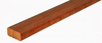
- Wooden ↓
- Steel ↓
Of course, in real construction, beam structures are also subject to other types of loading (wind load, vibration, alternating loading), however, the main calculation of horizontal, multi-supported and rigidly fixed beams is carried out under the action of either transverse or equivalent load reduced to it.
The calculation scheme considers the beam as a rigidly fixed rod or as a rod mounted on two supports. If there are 3 or more supports, the rod system is considered statically indeterminate and the calculation of deflection of both the entire structure and its individual elements becomes significantly more complicated.
In this case, the main load is considered as the sum of forces acting in the direction perpendicular to the section. The purpose of the deflection calculation is to determine the maximum deflection (deformation) which should not exceed the limit values and characterizes the rigidity of both an individual element (and the entire building structure associated with it.
Basic provisions of calculation methods
Modern construction methods for calculating rod (beam) structures for strength and rigidity make it possible, already at the design stage, to determine the value of the deflection and make a conclusion about the possibility of operating the building structure.
Calculation of rigidity allows us to resolve the issue of the greatest deformations that can occur in a building structure under the complex action of various types of loads.
Modern calculation methods, carried out using specialized calculations on electronic computers, or performed using a calculator, make it possible to determine the rigidity and strength of the research object.
Despite the formalization of calculation methods, which involve the use of empirical formulas, and the effect of real loads is taken into account by introducing correction factors (safety factors), a comprehensive calculation quite fully and adequately assesses the operational reliability of a constructed structure or a manufactured element of a machine.
Despite the separateness of strength calculations and determination of structural rigidity, both methods are interrelated, and the concepts of “rigidity” and “strength” are inseparable. However, in machine parts, the main destruction of an object occurs due to loss of strength, while structural mechanics objects are often unsuitable for further use due to significant plastic deformations, which indicate low rigidity of structural elements or the object as a whole.
Today, in the disciplines “Strength of Materials”, “Structural Mechanics” and “Machine Parts”, two methods of calculating strength and stiffness are accepted:
- Simplified (formal), during which aggregated coefficients are used in calculations.
- Refined , where not only safety factors are used, but also contraction is calculated based on limit states.
Stiffness calculation algorithm
Formula for determining the bending strength of a beam
Where:
- M – maximum moment occurring in the beam (found from the moment diagram);
- Wn,min – moment of resistance of the section (found from the table or calculated for a given profile), a section usually has 2 moments of resistance of the section, Wx is used in calculations if the load is perpendicular to the x-x axis of the profile or Wy if the load is perpendicular to the yy axis;
- Ry – design resistance of steel in bending (set in accordance with the choice of steel);
- γc – operating conditions coefficient (this coefficient can be found in Table 1 SP 16.13330.2011;
The algorithm for calculating rigidity (determining the amount of deflection) is quite formalized and is not difficult to master.
In order to determine the deflection of the beam, it is necessary to perform the following steps in the sequence below:
- Draw up a design diagram of the research object.
- Determine the dimensional characteristics of the beam and design sections.
- Calculate the maximum load acting on the beam, determining the point of its application.
- If necessary , the beam (in the design scheme it will be replaced by a weightless rod) is additionally checked for strength by the maximum bending moment.
- The value of the maximum deflection is determined , which characterizes the rigidity of the beam.
To draw up a design diagram of a beam, you need to know:
- Geometric dimensions of the beam , including the span between the supports, and if there are consoles, their length.
- Geometric shape and cross-sectional dimensions.
- The nature of the load and the point of their application.
- Beam material and its physical and mechanical characteristics.
In the simplest calculation of two-support beams, one support is considered rigid, and the second is hinged.
Determination of moments of inertia and section resistance
The geometric characteristics that are necessary when performing strength and stiffness calculations include the moment of inertia of the section (J) and the moment of resistance (W). To calculate their values, there are special calculation formulas.
Section modulus formula
Determination of maximum load and deflection
Formula for determining deflection
Where:
- q – uniformly distributed load, expressed in kg/m (N/m);
- l – beam length in meters;
- E – elastic modulus (for steel equal to 200-210 GPa);
- I – moment of inertia of the section.
When determining the maximum load, it is necessary to take into account a fairly significant number of factors acting both constantly (static loads) and periodically (wind, vibration shock load).
In a one-story house, the wooden beam of the ceiling will be subject to constant weight forces from its own weight, partitions located on the second floor, furniture, occupants, and so on.
Features of deflection calculations
Of course, the calculation of floor elements for deflection is carried out for all cases and is mandatory in the presence of a significant level of external loads.
Today, all calculations of the deflection value are quite formalized and all complex real loads are reduced to the following simple calculation schemes:
- A rod resting on a fixed and hinged support, perceiving a concentrated load (the case is discussed above).
- A rod resting on a fixed and hinged rod on which a distributed load acts.
- Various loading options for a rigidly fixed cantilever rod.
- The action of a complex load on a design object - distributed, concentrated, bending moment.
Load collection
Before starting the calculation, the forces acting on the I-beam are collected. Depending on the duration of exposure, they are divided into temporary and permanent.
Table of loads on I-beams
| Permanent | Self-weight of beams and floors. In a simplified version, the weight of the interfloor floor without a cement screed, taking into account the mass of the beam, is taken equal to 350 kg/m2, with a cement screed - 500 kg/m2 | |
| Long-term | Useful | Depends on the purpose of the building |
| Short-term | Snowy, depend on the climatic conditions of the region | |
| Special | Explosive, seismic. For beams operating under standard operating conditions are not taken into account. Online calculators usually do not take into account | |
Loads are divided into standard and design. Regulatory standards are established by building codes and regulations. The calculated values are equal to the standard value multiplied by the reliability coefficient. With a force of less than 200 kg/m2, the coefficient is usually taken equal to 1.3, with more than 200 kg/m2 - 1.2. The pitch between the beams is taken equal to 1 m. In some cases, if this is permissible under specific operating conditions, in order to save materials it is taken equal to 1.1 or 1.2 m.
When calculating, take into account the grade of steel. For use under conditions of high loads and at sub-zero temperatures, I-beams made of low-alloy steels are in demand.
Price
The price of an I-beam 20B1 is determined based on the type of metal used for its manufacture. Low-carbon steel is the most economical; it is used for the manufacture of profiles operating under light loads. You can buy an I-beam 20B1 made of high-strength steel for a large sum, but its load-bearing capacity will be higher.
The price per ton of I-beam 20B1 also depends on the quality of the product. On average it is 50 thousand rubles, a meter of product costs 1200 rubles. For large order volumes, the manufacturer often makes a discount.
Return to content
Methods for choosing the optimal profile section size
The most accurate option for selecting the number and type of I-profile is to carry out professional calculations. It is this method that is used when designing critical large-sized objects. When constructing small buildings, you can use an online calculator.
To approximately determine the size of the profile, you can use the table corresponding to the number of the I-beam and the maximum permissible load:
| Total load, kg/m2 | Span length | ||||||||
| 3 m at step, m | 4 m at step, m | 6 m at step, m | |||||||
| 1,0 | 1,1 | 1,2 | 1,0 | 1,1 | 1,2 | 1,0 | 1,1 | 1,2 | |
| 300 | 10 | 10 | 10 | 10 | 12 | 12 | 16 | 16 | 16 |
| 400 | 10 | 10 | 10 | 12 | 12 | 12 | 20 | 20 | 20 |
| 500 | 10 | 12 | 12 | 12 | 12 | 12 | 20 | 20 | 20 |
From this table it can be seen that for I-beam number 10 the maximum span length is 4 m with a step of 1.2 m, the load is 400 kg/m2, for number 16 the span length can reach 6 m, the load it can withstand is 300 kg/m2, for a profile of 20 – 6 m and a load of 400 kg/m2.
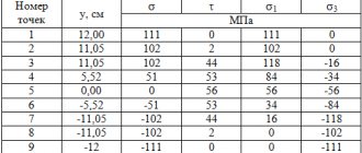
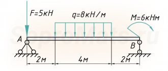
Construction of diagrams Q and M
A detailed example of constructing diagrams of transverse forces Q and bending moments M for a beam
Internal force factors Qy and Mx in the beam span 0 ≤ z2 ≤ l
QII= — RB+ qz2= -52+30∙z2 QII(z=0)= -52 kN QII(z=l)= -52+30∙4=68 kN
MII=RB∙z2-qz22/2=52z2-30∙z22/2 MII (z=0)= 0 MII (z=l)= -32 kNm
On the console l ≤ z1≤ (l+a)
QI= — RB+ ql — RA=-52+30∙4-108=-40 kN
MI=RB z1-ql(z1-l/2)+RA(z1-l)=52z1-30∙4(z1-4/2)+108(z1-4) MI (z=l)= -32 kNm MI (z=l+a)= 0
Based on these data, diagrams of Q and M were constructed.
see also
Comments 39
For some reason, one truss was initially laid, which bears all the snow and structural load. It is much more rational to distribute the load across three to four trusses with a cross section of 300 mm, made of 40x25 corrugated pipe with struts made of 14 mm reinforcement. During installation, the trusses are tied together with cross braces for stability. Then you can lay the floor of the second floor on them. Something like that. In fact, there was already a proposal above to contact engineers. On your turbogenerator they have not yet disappeared. Hello Lysva! I was on a business trip with you about 40 years ago...
There is such a calculator vladirom.narod.ru/stoves/beamcalc.html, although for wooden beams, you seem to have them, it might come in handy! In general, it’s better to pay the company, let them do the calculations for you, it’s quite quick and the money will most likely come out to no more than 1-2 thousand rubles.
Oh, these advisors. They just come up with a lot of things. Perm - 5th snow region = 320kg/m2. Wooden floor structure = 15 kg/m2 Useful load on the floor (people, furniture) = 100 kg/m2 Blood structure (on the side) = 30 kg/m2 Beam load area = 6.61 m x (7.61/2) = 25.2 m2 . Total load on the entire length of the beam = 465 kg * 25.2 m2 = 11.7 t. Uniformly distributed load = 11.7t / 6.61m = 1.78t. (per linear meter).
Result of selection of elements: - I-beam - 40B1. — I-beam — 30Ш1. — I-beam — 20K2. - Channel — The selection could not be made. Great deflections.
I advise you to use 30Ш1 - it has a larger shelf width. It will be easier to do the support. My pleasure.
And instead of the “I-beam - 30Ш1”, isn’t it cheaper to calculate and weld a truss? A truss without calculations can cost 50-100% more due to the use of a too large profile.
Don't make things up. Truss 6.6 m long. from the corners in tonnage will weigh 200-250kg + work to make the truss. The I-beam weighs 380 kg. Where is the 100% benefit here? In addition, the truss structure has a height of 600-800mm, which reduces the height of the ceiling. Is it necessary? Do not mislead people if you are not competent in the matter. Trusses can be rationally used in large span buildings. For a garage this is absolutely pointless. I’m telling you this as a design engineer.
I meant that a farm without calculations can cost 50-100% more than a calculated farm. As a rule, without calculation, stronger rolled products are used than required by calculation. And an extra 3-5 times safety margin may be impractical.
If the roof structure did not rest on a beam (floor), it would be easy to calculate which channel or I-beam to use, but with such a roof structure, the entire bulk of the roof rests on the calculated beam.
I would prefer to weld two channels instead of 2t
Cook the farm. Don't make things up. I have about 100 professional pipes, but that’s a lot. From 60 it will be normal.
To avoid future troubles in the form of collapse of the ceiling or severe sagging of the beam and further destruction, I would entrust the calculation to a civil engineer. And if you listen to amateurs, it will be scary to enter this garage (especially in winter after a heavy snow load on the roof).
Calculation of a metal floor beam
There are cases when it is not economically profitable to use wooden beams for interfloor or attic floors.
For example, when the span is too large and therefore large cross-section wooden beams are required to cover it. Or when you have a good friend who sells not lumber, but rolled metal. In any case, it will not hurt to know how much the ceiling can cost if you use metal beams rather than wooden ones. And this calculator will help you with this. With its help, you can calculate the required moment of resistance and moment of inertia, which are used to select metal beams for the floor according to the assortments based on the conditions of strength and deflection .
The floor beam is calculated for bending as a single-span simply supported beam.
Calculator
Related calculators:
- Collection of loads on floor beams online.
Instructions for the calculator
Initial data
Span length (L) is the distance between the two inner edges of the walls. In other words, the span that the calculated beams cover.
Beam pitch (P) is the step along the center of the beams through which they are laid.
Type of ceiling - if you will not live on the top floor, and it will not be heavily cluttered with things dear to your heart, then select “Attic”, in other cases - “Interfloor”.
Wall length (X) - the length of the wall on which the beams rest.
Beam length (A) is the largest dimension of the beam.
Weight 1 lm . — this parameter is used as if in the second stage (after you have already selected the desired beam).
Design resistance Ry - this parameter depends on the steel grade. For example, if the steel grade is:
- C235 - Ry = 230 MPa;
- C255 - Ry = 250 MPa;
- C345 - Ry = 335 MPa;
But usually Ry = 210 MPa is used in the calculation in order to protect oneself from various kinds of “force majeure” situations. After all, we live in Russia - they will bring rolled metal from the wrong grade of steel and that’s it.
Elastic modulus E - this parameter depends on the type of metal. For the most common ones, its value is:
- steel - E = 200,000 MPa;
- aluminum - E = 70,000 MPa.
The values of standard and design loads are indicated after they are collected on the floor.
Price per 1 ton - the cost of 1 ton of rolled metal.
Result
Strength calculation:
Wreq is the required moment of resistance of the profile. It is located according to the assortment (there are GOSTs for profiles). The direction (x-x, yy) is selected depending on how the beam will lie. For example, for a channel and an I-beam, if you want to place them (i.e. the larger size is directed upward - [ and Ι ), you need to select “xx”.
Deflection calculation:
Jreq is the minimum permissible moment of inertia. Selected according to the same assortments and according to the same principles as Wreb.
The number of beams is the total number of beams that is obtained when laying them along the wall X with a step P.
Total mass - the weight of all beams of length A.
Cost - the cost of purchasing metal floor beams.
Taking steel grade into account when determining strength
When calculating strength, the grade of steel is taken into account. For difficult climatic conditions, the I-beam is made of non-brittle steel. It is better to choose the most durable brands. Here it should be taken into account that a product of higher strength may have smaller dimensions and, therefore, the permissible pressure will be less.
That is why a competent calculation of strength is performed in several different versions, then the parameters are compared. To determine the strength, it is necessary to decompose the applied force along the axes and determine the maximum moments around these axes.