An example of solving the problem of a complete calculation of the strength and stiffness of a steel I-beam for a given system of bending loads.
Task
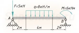
Perform a full strength calculation and check the rigidity of a statically determinate I-beam with two supports (Fig. 1) with the following data: F=40kN, q=30 kN/m, a
=0.8 m,
l
=4m, permissible normal and tangential stresses: [σ]=160 MPa and [τ]=100 MPa, permissible beam deflection [f]=
l
/400
Rice. 1
More sample solutions > Help with problem solving >
Solution
Construction of diagrams Q and M
A detailed example of constructing diagrams of transverse forces Q and bending moments M for a beam
Internal force factors Qy and Mx in the beam span 0 ≤ z2 ≤ l
QII= — RB+ qz2= -52+30∙z2 QII(z=0)= -52 kN QII(z=l)= -52+30∙4=68 kN
MII=RB∙z2-qz22/2=52z2-30∙z22/2 MII (z=0)= 0 MII (z=l)= -32 kNm
On the console l ≤ z1≤ (l+a)
QI= — RB+ ql — RA=-52+30∙4-108=-40 kN
MI=RB z1-ql(z1-l/2)+RA(z1-l)=52z1-30∙4(z1-4/2)+108(z1-4) MI (z=l)= -32 kNm MI (z=l+a)= 0
Based on these data, diagrams of Q and M were constructed.
1. Collection of loads Before starting the calculation of a steel beam, it is necessary to collect the load acting on the metal beam. Depending on the duration of action, loads are divided into permanent and temporary.
Constant loads include:
- own weight of the metal beam;
- own weight of the floor, etc.;
Temporary loads include:
- long-term load (payload, taken depending on the purpose of the building);
- short-term load (snow load, taken depending on the geographical location of the building);
- special load (seismic, explosive, etc. Not taken into account within this calculator);
Loads on a beam are divided into two types: design and standard. Design loads are used to calculate the beam for strength and stability (1st limit state). Standard loads are established by standards and are used to calculate beams for deflection (2nd limit state). Design loads are determined by multiplying the standard load by the reliability load factor. Within the framework of this calculator, the design load is used to determine the deflection of the beam to reserve.
The general calculation of metal structures can be read on our website.
Loads can be collected on our website.
After you have collected the surface load on the floor, measured in kg/m2, you need to calculate how much of this surface load the beam takes on. To do this, you need to multiply the surface load by the pitch of the beams (the so-called load strip).
For example: We calculated that the total load was Qsurface = 500 kg/m2, and the beam spacing was 2.5 m.
Then the distributed load on the metal beam will be: Qdistributed = 500 kg/m2 * 2.5 m = 1250 kg/m. This load is entered into calculator 2. Constructing diagrams
Next, a diagram of moments and shear forces is constructed.
The diagram depends on the loading pattern of the beam and the type of beam support. The diagram is constructed according to the rules of structural mechanics. For the most frequently used loading and support schemes, there are ready-made tables with derived formulas for diagrams and deflections. 3. Calculation by strength and deflection
After constructing the diagrams, calculations are made by strength (1st limit state) and deflection (2nd limit state).
In order to select a beam based on strength, it is necessary to find the required moment of inertia Wtr and select a suitable metal profile from the assortment table. The vertical maximum deflection fult is taken according to table 19 from SNiP 2.01.07-85* (Loads and impacts). Point 2.a depending on the span. For example, the maximum deflection is fult=L/200 with a span of L=6m. means that the calculator will select a section of a rolled profile (I-beam, channel or two channels in a box), the maximum deflection of which will not exceed fult=6m/200=0.03m=30mm. To select a metal profile based on deflection, find the required moment of inertia Itr, which is obtained from the formula for finding the maximum deflection. And also a suitable metal profile is selected from the assortment table. 4. Selection of a metal beam from the assortment table
From the two selection results (1st and 2nd limit state), a metal profile with a large section number is selected.
Selection of the cross-section of an I-beam
Since Mmax = 45 kNm, then
Wx≥Mmax / [σ] = 45∙103 / 160∙106= 0.281 m3= 281 cm3
.
How to select a beam section
According to the assortment, we select I-beam No. 24, for which Wx = 289 cm3, Ix = 3460 cm4, Smax = 163 cm3, h = 24 cm, bп = 11.5 cm, t = 0.95 cm, d = bc = 0.56 cm, h0 = h-2t = 22.1 cm.
This I-beam will operate at the maximum normal stress in the extreme fiber of the dangerous section.
σmax = Mmax / Wx = 45∙103 / 289∙10-6= 156∙106 Pa = 156 MPa
Definition - boom - deflection
Determination of the deflection and compressive strength is optional, if it is not specified in the order specifications.
In addition to determining the deflection and crushing stresses, the total stresses σ2 arising in the camshaft from the combined action of bending and twisting moments are sometimes determined.
In addition to determining the deflection and crushing stresses, the total stresses as arising in the camshaft from the combined action of bending and twisting moments are sometimes determined.
To determine the deflection, a sheet of material is placed with the bent side up on a horizontal plane. A ruler with a preferred length of 1000 mm is applied parallel to the edge of the sheet. The weight of the ruler should not affect the measurement result. Measure the maximum distance (clearance) between the ruler and the surface of the sheet.
To determine the deflection of the belt, you need to attach a ruler to the belt and press your thumb on the belt in its middle part with force: for engines of GAZ and ZIL-3-4 cars, for YaMZ - about 10 kgf, thus establishing how many millimeters it deflected belt.
To determine the belt deflection, you need to attach a ruler to the belt and press your thumb on the belt in its middle part with a force: for GAZ and ZIL car engines - 3 - 4, for YaMZ - about 10 kgf, while the belt deflection for GAZ engines should be 12 - 20, for ZIL-120, 121 and GAZ-21 - 10 - 15, for YaMZ - 13 - 19, for ZIL-158, Ural-15 - 20 mm.
When determining the deflection of stepped shafts, a certain average diameter is taken into account.
Formula (16.31) for determining the deflection arrow in the middle of the rod with an eccentric application of load is approximate, since the curved axis of the rod is taken in the form of a half-wave of a sinusoid.
Control of curvature requires determining the deflection in the longitudinal section of the product when scrolling it on knives.
A feature of the calculation of these shavers is the determination of the deflection of the side surface of the teeth and the change in tooth thickness along the length of the shaver.
Checking the beam section using tangential stresses
Since Qmax = 68 kN, then
Construction of diagrams of normal σ and tangential τ stresses in an unfavorable section of the beam:
Constructing a diagram of normal stresses
Constructing a diagram of tangential stresses
In terms of principal stresses, the section above the left support is unfavorable, in which:
M = -32 kNm and Q = 68 kN.
The stress values at various points along the I-beam height are summarized in Table 1
Table 1
Calculation results in the example
Ways to perform deflection calculations and tests
The reason why SNiPs establish such draconian restrictions is simple and obvious. The smaller the deformation, the greater the margin of strength and flexibility of the structure. For a deflection of less than 0.5%, the load-bearing element, beam or slab still retains elastic properties, which guarantees normal redistribution of forces and maintaining the integrity of the entire structure. As the deflection increases, the building frame bends, resists, but stands; when the permissible value is exceeded, the bonds break, and the structure loses its rigidity and load-bearing capacity like an avalanche.
There are several ways to calculate the deflection of a structure:
- Use an online software calculator, in which standard conditions are “hardwired”, and nothing more;
- Use ready-made reference data for various types and types of beams, for various supports of load patterns. It is only necessary to correctly identify the type and size of the beam and determine the desired deflection;
- Calculate the permissible deflection with your hands and your head; most designers do this, while controlling architectural and construction inspectors prefer the second method of calculation.
By measuring how much the ceiling beam has sagged, you can determine with 99% certainty whether the structure is in disrepair or not.
Load Definition
The ceiling, together with the objects on it, creates a certain load on the wooden beams. It can be calculated accurately only in design organizations. An approximate calculation is made using a calculator using the following recommendations:
- Attics insulated with mineral wool and lined with boards have a minimum load, approximately 50 kg/m2. The load is calculated according to the formula: the safety factor value is 1.3 multiplied by the maximum load value - 70.
- If instead of mineral wool a heavier heat insulator and a massive backing board are used, the load increases to an average of 150 kg/m2. The total load can be determined as follows: the safety factor value is multiplied by the average load and the size of the required load is added to everything.
- When making calculations for the attic, the load is allowed up to 350 kg/m2. This is due to the fact that the weight of the floor, furniture, etc. is added.
We've sorted out this definition, now let's move on.
Additional functions of an I-beam in private housing construction
The floor itself does not necessarily have to consist only of metal I-beams. Often they are used only in the most intense places, and wooden I-beams are installed between the metal parts.
Why is that? The fact is that welding requires highly qualified workers. Further, in ordinary literature and Internet sites there is not that variety of components and ready-made design diagrams for installing such a ceiling; a competent engineer is really required here, and even we only give recommendations. In addition, metal is not cheap. And the quality of welding is very important. It must work for a long time, even under conditions of corrosion or changing loads.
Therefore, this option not only has the right to life, but is also quite practical:
And finally, a metal I-beam often serves as an additional functional element, which has value in any household:
Beam strength and rigidity
Beams in the house
Modern construction technologies used to calculate building structures, also called core structures, based on the qualities of strength and rigidity, provide a unique opportunity to calculate the amount of deflection at the very first stage of design.
In addition, based on the calculated data, it is possible to draw a conclusion about the likelihood of using the building structure.
What question does the following formula for calculating stiffness allow you to solve? Data obtained in this way indicates the largest changes in part geometry that can occur in a building structure.
Despite some bureaucratization of methods for calculating deflection, experimental formulas are used, and if the effect of real loads differs from ideal or average ones, the issue is resolved by introducing additional factors for the safety factor. The concepts of “rigidity” and “strength” are related and absolutely inseparable.
Although there are still some differences. But only if we consider these indicators in cars. In building structures, the main violation of the design of objects occurs because issues related to the safety margin are reduced or completely eliminated, as a result of which the buildings cannot be used.
Wooden beams made of softwood
Today, in such subjects of study as “Sopromat” and others, 2 methods have been adopted for calculating strength and stiffness:
- Simple. When calculating indicators based on this method, an increased coefficient is used.
- Accurate. Here, not only coefficients are used that show the safety factor, but the boundary state is also calculated (how much load the beam can withstand).
How to calculate deflection for a house beam
To calculate whether a particular beam is suitable for building a house, you need to know the following indicators:
- M is the maximum moment that occurs in the beam, located on the moment diagram. A diagram is a special drawing depicting a spatial figure depicted on a plane.
- W n, mіn – moment of resistance of the section (its value is found from the table).
- Ry is the resistance that the material from which the structural element of the house is made exhibits when bending under the load.
- Uc is an additional indicator (it can be found in one of the many tables of building regulations).
The formula for calculating deflection is an inequality of the following form (formula No. 1):
M / (W n, min* Ry * Уc) ≤1
To apply the formula correctly, you need to do this:
- Draw a schematic diagram of the beam and its future location under the roof of the house. In order to correctly depict all parts of the object under study in the drawing, you need to know the shape and linear dimensions of the beam, cross section, the nature of future loads, and the material from which the beam is made.
- Write down its exact dimensions.
- Calculate using the specified formula what is the quotient of the maximum moment of the beam to the product of the other three quantities.
- Compare the result with one: if it is less than or equal to 1, then the calculations give a positive answer.
Knowing the value of the parameters of the beam in question and the forces acting on it, having made simple calculations, you can quickly cope with the task of calculating the permissible deflection of the beam of the house.