Using homemade machines in the workshop
The work that is performed in the workshop affects the equipment of the room with special devices. Typically, equipment is placed if the free area is at least 3 m2.
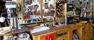
Workshops are often set up in small rooms, outbuildings, and garages. The best place is a separate building. In this case, the noise from the work being performed will not disturb other residents of the house.
Universal workshops are often set up to perform various jobs. If a person is engaged in the production of any products, then specific homemade tools and devices are made. Often workshops are equipped with machines for carpentry and processing of metal blanks. Often, premises for the repair of wheeled vehicles are also set up.
Basically the workshop is equipped with:
- devices that allow you to prepare tools, facilitate labor and mechanize operations;
- homemade products for processing metal parts;
- workbenches.
A workbench made of wooden elements Source skilljob.ru
It is also necessary to install shelves in the room where various tools will be stored. At the same time, they ensure unhindered access to them and compliance with fire safety rules.
Selecting a transfer method
The transmission of torque from the engine to the workpiece can be carried out in two ways.
Direct transmission
Direct transmission of the drive to the workpiece is the simplest design method, but not the most perfect. Disadvantages of direct transmission:
- It is impossible to regulate the rotation speed, since the motor without additional units cannot change the rotation speed by simply changing the incoming voltage. This drawback is especially noticeable when working with hardwood, such as oak, teak or apple tree.
- High load on the motor shaft and shorter service life compared to belt drive. Heavy products will have a particularly strong effect on engine wear. This is primarily due to the fact that the bearings of most motors (except for motors in washing machines) are not designed for longitudinal load. You will also have to pay more attention to the centering of the material, because any inaccuracy will lead to excessive vibrations, which at high speeds can make the work impossible.
Belting
This method of transmitting rotation guarantees a longer service life of the motor and makes it possible to regulate the speed of rotation of the workpiece. In this case, the engine itself is located offset from the axis of rotation of the wooden product, and the torque is transmitted using a belt and several pulleys.
If you provide the machine with pulleys of several radii, it will be possible to change the rotation speed of the headstock. With three or more pulleys of different diameters, you can tackle hardwood with confidence. If you stock up on the necessary tools, you can even work with soft alloys.
Workbench for a carpenter
This type of equipment is a table. It is distinguished by its high strength and the presence of 2 vices on the tabletop. The table is also equipped with clamps that clamp the workpieces during planing. In addition, the workbench may still have places where other homemade devices, such as a router, will be attached.
A special table must have a comfortable height. She matches the height of the master. The minimum length of the workbench is 1000 mm. Often it is equal to 1700 mm or even 2000 mm. The standard width is 800 mm.
Before making a workbench for carpentry, get acquainted with its main parts Source infourok.ru
A workbench table is created as follows:
- The table surface is created - this is a shield, which is made from oak, beech or hornbeam boards with a minimum thickness of 55 mm. They are tightly fitted to each other. The boards used are impregnated with drying oil before joining. To create a rigid structure, a 50 mm block is used. It is fixed around the perimeter of the working surface.
- The supporting elements of the workbench are made. To do this, use linden or pine timber. Its size is 120*120 mm or 150*150 mm, and its length is approximately 1200 mm. The supports are connected by jumpers in the horizontal plane. To do this, take boards that are fixed at a distance of 300 mm from the floor.
- Make homemade devices to accommodate the tool. These are shelves located under the countertop. When they are open, they are often replaced with bedside tables.
- Attach a vice.
If a stationary workbench is created, its supporting elements are fixed to the floor. Depending on the specifics of the work being performed, mobile and collapsible tables are also manufactured.
Mobile workbench on wheels Source foamin.ru
Carpenter's workbench vice
This homemade tool is made using a screw rod. Its thread length must be at least 160 mm. In this case, the diameter of the rod itself must be 20 mm. For the vice you will also need wooden blocks and metal pins. The manufacturing sequence is as follows:
- Prepare a block of 200*300 mm. Its minimum thickness should be 50 mm. This will be one of the sponges. A hole for a screw is drilled in the center of the workpiece. On the sides of it, two more holes are made for the studs.
- A second movable jaw 200*180 mm is cut out and similar holes are drilled in it.
- A threaded pin is inserted into the workpiece. A handle is installed at one end. To prevent the jaws from moving, pins with a cross section of 10 mm are passed through other holes.
Wooden vice for a carpenter Source infradom.ru
How to make a milling table with your own hands?
Many craftsmen adapt an ordinary workbench as a table for a router. However, in practice it has been proven that it is better to have a separate specialized design. The explanation is simple:
- during operation, vibration will occur, which can lead to an unstable position of parts on the workbench;
- To move up and down you will need a special device (elevator). In a regular workbench there is often no free space.
An important feature of the router is the need to install a base plate connected to the table top. For it I use metal, plexiglass or durable plywood. Fixation is carried out using holes
Most manufacturers of hand tools provide fasteners for their products in advance, assuming that a significant part of their products will also be used in a stationary version
Fixation is carried out using holes. Most manufacturers of hand tools provide fasteners for their products in advance, assuming that a significant part of their products will also be used in a stationary version.
Various cutters are used during work
Milling methods using different types of shaped cutters
Based on a study of known designs, a number of basic requirements for a milling table have been formulated.
- The support plate should be located in the same plane as the table. When moving workpieces, vertical displacement on the support is not allowed. Some craftsmen leave the base sole. They bring it to “zero” with the tabletop. But most agree that another plate needs to be made.
- For convenience and safe use of the machine, the on and off buttons should be located so that they can be quickly used. A situation may arise when you urgently need to turn off the power to the engine.
- The workpieces are moved relative to the stop. It can be shifted so that the master has the opportunity to mill edges, as well as grooves in semi-finished products.
- It is useful to think about the installation location of the machine. You need a convenient hike to get there. You may have to mill the length. Then the workpieces should be placed on both sides of the table.
- Some craftsmen adapt the installation of only the tabletop to an existing machine. This makes it possible to combine several devices on one frame.
Even an ordinary table can be converted into a machine. An example of such a transformation is shown in the video.
To get the most out of the machine, you need to minimize the thickness of the base plate. Then the cutter overhang will be maximum. In practice, long finger cutters can be used for deep milling. Strength will be ensured only by fairly rigid materials.
Installation of the vertical movement device
The upward and downward movement of a hand router is carried out using a device called an elevator. Here, a variety of mechanisms are used to move and fix a given position.
A possible elevator option is shown in the video.
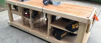
Metal workbench for a mechanic
All useful homemade products and devices simplify the processing of workpieces. Such devices include a workbench for a mechanic. Its minimum dimensions are:
- length – 1800 mm;
- width – 700 mm;
- height – 900 mm.
The table is created in the following sequence:
- frame assembly;
- installation of 2 cabinets, covered with metal;
- securing a working surface consisting of a wooden base in the form of a shield, on which a sheet of metal of a suitable size is placed on top;
- assembly and installation of a rack at the back of the workbench to strengthen the entire structure and accommodate tools.
When assembling a bench, use:
- beams as racks - four corrugated pipes 40*60 mm with a wall thickness of at least 2 mm;
- three beams 50*40 mm to connect the racks and ensure longitudinal rigidity of the structure;
- corrugated pipe 40*30 mm with a wall of at least 1 mm in the amount of 9 pieces to create the frame of the cabinets;
- metal corner 50*50 mm for the manufacture of shelving racks, the height of which will be a maximum of 2000 mm;
- board 50 mm thick for the tabletop panel;
- a sheet of metal no thinner than 6 mm to cover the top surface of the workbench.
Sheet metal Source glavmetall.com
See also: Catalog of construction companies that have their own production of materials and components for the construction of houses
Safety precautions
When installing a milling table, it is necessary to ensure grounding of the equipment and the outlet into which it is plugged in. The current must correspond to that specified in the passport. Before use, connect the vacuum cleaner. It not only removes chips from the cutting area and makes processing cleaner, but also cleans the air from wood particles, dust, and resin that are harmful to humans. The spindle must be locked when installing and changing tools. Use cutters with a shank diameter that matches the collets included with the router.
Each master makes a milling table for himself, inventing his own design or altering the drawings of others. The more work will be performed on the device, the stronger and more reliable the base should be. Lovers of order, who have everything in a strictly defined place, should make a machine from a desk or make the base and cabinets with drawers yourself. In a workshop with a large volume of carpentry work, a combined device with additional space for a jigsaw and a circular saw is suitable. For those who periodically make crafts for the home, a portable table is suitable, which can always be set up in a few minutes and a router screwed to it.
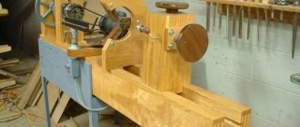
Wood lathe for lathe
There are various homemade machines and machines for the workshop. They all make the job easier. These include a lathe. Its structural elements are:
- Durable frame made of metal angle or pipe. Sometimes it is created from wooden blocks. The bed is fixed to the floor, and its lower part is weighted.
- A support, which is a supporting element for the cutters. This part of the machine must provide reliable fixation and allow the workpiece to move to the side. For this purpose, the design provides a screw rod.
- The clamping spindle, also called the headstock. The head of a powerful electric drill is often used as it.
The head of an electric drill is often used as a headstock. Source woodtoolsimg.ru
- Tailstock used for longitudinal movement of the workpiece. It is recommended to use the factory spindle, which has four cams.
- Electric drive providing rotation of 1500 rpm. Its power should be from 250 to 400 W. Often a washing machine motor is used as an electric motor. The design also includes a belt drive. This is a transmission, for the operation of which it is necessary to install pulleys on the shafts.
The electric motor of washing machines is often used as a drive for a lathe. Source dobro-teh.ru
Cutters for the machine
It is recommended to equip homemade devices with factory cutters. After all, they are sharpened with high quality using special equipment. As a last resort, for production use:
- old files without significant defects;
- steel square reinforcement is the optimal material for making cutters;
- square or rectangular spring from the car.
Subsequently, the existing workpieces are sharpened. Creates a semi-circular cutting edge for roughing wood parts. Finish turning work is carried out with a cutter that has a straight blade.
After sharpening, the cutting elements are hardened. During this process, the cutters are first heated and then placed in machine oil.
Wood boring tools for a lathe Source 24aul.ru
A simple way to make your own frame
The reliability of the bed is a key characteristic of the machine. Human safety and the quality of the product depend on the properties of the material and the quality of the connection of the parts of the frame.
Based on these requirements, the choice falls on metal profiles, chipboard, plywood or solid wood (preferably solid wood: oak, birch or the most common: pine).
If the choice is on a metal frame, then you need to choose a channel, an I-beam or a profile pipe that will carry the load-bearing functions of the machine. Here the choice depends solely on the availability of the material, its price and ease of installation. However, the metal frame is the simplest in design: you only need two I-beams, on which the engine, tailstock, tool rest and caliper are then mounted.
If the choice is wood or chipboard, then based on a preliminary sketch-drawing with the existing dimensions of the engine and all other elements, the design of the frame is formed. As a rule, it consists of a table top, which acts as a base, a stand for the tailstock and a box on which the motor and headstock axle are mounted.
In addition, two parallel slats are run between the headstock racks, on which a movable support board is attached. A gap of 5 cm is maintained between the slats. Afterwards, it is necessary to weld the frame with a welding machine - this will give additional strength to the structure.
If the machine is supposed to be a tabletop machine, then there is no need for legs, but when processing heavy and massive elements, the bed should be independent and its stability should not raise questions. In this case, it is necessary to provide legs. They are made from rolled steel, for example, angle or timber.
The dimensions of the machine primarily depend on the goals pursued by the master. Most operations at home are performed with products up to 80 cm in length, so most often the length dimensions of the machine are 80 cm. If the frame is made of metal, then two blanks of equal length are cut with a grinder.
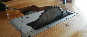
Stationary circulation saw
The stationary circular saw is placed on a sturdy table. Its working surface is usually made of metal sheet. It is reinforced with stiffening ribs. For their manufacture, a steel angle is used.
On the working surface there are usually:
- stops;
- guides;
- elements for adjustment;
- cutting disc.
On a note! The circular saw is powered by an electric motor. Its power should be approximately 800 W, and its rotation should be 1700 rpm. The electric motor of the angle grinder corresponds to these characteristics.
Angle grinder for a stationary circular saw Source tdrim.ru
Before making a device for sawing wooden parts, prepare a working angle grinder with the necessary characteristics. Further actions are performed in the following order:
- Assembling the frame.
- Prepare a worktop in which a slot is made for the cutting disc.
- Two wooden blocks are fastened in parallel. They will be used as stops.
- Set the scale necessary to control the cutting of wooden parts.
- Clamps are installed so that workpieces and guides can be fixed.
- The grinder is secured by first installing the disk into the previously created slot in the table top. The power tool is fixed from below the working surface.
Hammer upgrade
A common occurrence is a wooden handle falling out of the hammer socket. One of the ways to create a reliable handle fastening is to make a cut in the upper end of the handle. The holder is inserted into the hammer socket. The cut is filled with Moment glue. A wooden wedge is driven into the groove.
In order not to look for nails while working, and especially not to hold them with your teeth, a round magnet is glued into the bottom of the hammer handle. Magnetic nails will always be at hand for the worker. It is dangerous for the hammer to accidentally fall out of your hand at height. To prevent this from happening, a hole is drilled in the handle through which the cord is threaded. The worker's belt is threaded through the loop.
Drilling machine
Interesting homemade products and devices often help craftsmen out when making various products in the workshop. One such device is a drilling machine. Its main parts include:
- electric drill;
- base made of metal parts with the ability to secure the workpiece;
- a stand for fixing an electric drill, which is created using chipboard with a thickness of 20 to 25 mm or an old photographic enlarger;
- a unit that supplies the drilling tool.
The drill press stand must have guide rails. They are necessary for the electric drill to move strictly in a vertical direction. There are different options for feeding an electric tool, but the most common design is a lever with a spring. It is manually controlled by simply pressing. The design of the machine also includes stops. They are needed to adjust the depth of the hole created in the part.
How to make a handicraft at home?
The support for guiding the cutter along the shaft of the workpiece is a tool rest. It is best to make it from a steel pipe or angle iron, because wooden supports wear out quickly and are not able to withstand as heavy loads as a metal part of the same size.
You can make it by welding two pipes in a T-shape, or you can do it even simpler and fix a piece of board with a wooden boss on the frame, but the accuracy and wear resistance of such a design is not durable. The main thing in arranging a tool rest is that the upper edge of the pipe or angle must correspond to the axis of rotation of the workpiece: in this case, the risk of breaking the chisel is minimal.
Important!
When working on a lathe, only the lower part of the workpiece can be processed! Failure to do so may cause the incisor to become jammed or fractured, which can result in serious injury. When operating a woodworking machine, be sure to wear safety glasses to reduce the risk of injury.
CNC router
There are homemade machines and devices of complex design. Such devices include a CNC router. It is made for processing metal and wooden parts.
Work with a CNC router is carried out to a higher quality. This machine has advanced capabilities. When creating it, an LPT port is used, and numerical control is also provided. The copying unit is created from printer carriages with a matrix of needles.
The milling device is assembled as follows:
- The tabletop is made using a plywood sheet. Instead, chipboard with a thickness of at least 15 mm is used.
- A cutout is created to accommodate the cutter.
- The milling unit is installed.
- The electric drive is located.
- The transmission is secured.
- The spindle is mounted.
- The stops are fixed.
The process of creating a wood router Source tmklazer.rf
A CNC milling machine for processing metal workpieces is made with a more durable frame. The device is created in the following sequence:
- The column and frame are mounted when using a channel. From them a structure in the shape of the letter “P” is created. In it, the bridge between two supporting elements is formed by a part that is the base of the milling unit.
- Guides are made from angle iron. They are fixed with bolts on the column.
- Guide consoles are created from a pipe with a rectangular cross-section. To move them to a height of maximum 150 mm, the design provides a car jack.
- A threaded pin is inserted into the console.
- A working surface is created.
- A vice, fixing elements and guides are installed.
- The rotating unit is mounted. In this case, they strictly ensure that the shaft is in a vertical plane.
Option 1. Instructions for making a table for a manual router
Materials for making a milling table
To build a milling table you will need:
- 4 square bars;
- chipboard and plywood scraps, the dimensions of which are determined when constructing the table drawing;
- hardware (nuts, bolts, screws, hinges, etc.);
- jack;
- metallic profile;
- six-millimeter steel plate;
- aluminum guides;
- movable carriage-support (guide from the saw);
- manual frezer.
Drawing of a homemade milling table (option 1)
In any case, before you start making any such table, the drawing must be completed indicating all dimensions and determining the location of the working elements relative to each other.
Step by step assembly
Let us consider in detail each step in the manufacture and fastening of each element of a homemade milling table.
1st step. To make a stationary base for the table, you will need bars and chipboard cuttings, from which we twist the legs and further strengthen the rigidity with the help of horizontal connecting panels made of plywood. In the right side part we cut a hole for the start button, which will be connected to the hand router.
2nd step. The table top is made of chipboard. We make it liftable together with a router, for which we install hinges and make an additional support base from 15 mm plywood.
3rd step. To move the workpiece smoothly along the table, for example, to cut a groove in it, a moving carriage-stop is used. We cut a groove in the tabletop for the guides of the movable stop and install a metal profile into it. You can use a guide from an old saw as a stop carriage.
4th step. We also make the longitudinal stop from chipboard and make it movable to adjust the gaps around the cutter. To ensure mobility, we cut perpendicular grooves in the upper part of the stop and fasten the stop to the tabletop with clamps. We cut a small groove in the middle to suck out chips and other milling waste.
5th step. From thin plywood we make a box with a hole for connecting a vacuum cleaner hose, which will remove dust and shavings formed during the milling process. We fasten the box behind the perpendicular stop.
6th step. We take a six-millimeter steel plate and screw it to the tabletop flush with the surface. During the fastening process, we make sure that its edges do not protrude above the tabletop, otherwise the parts being processed will cling to them. A manual router will be attached to the plate from below.
7th step. We attach the router by the aluminum base to the bottom of the plate using bolts, but do not forget to pre-drill holes for the bolts in the base. Attaching the hand tool to a removable plate rather than directly to the table saves routing depth and allows for easy cutter changes.
8th step. We are building a router lift. To do this, we use a car jack, which allows us to change the height of the cutter with maximum accuracy.
9th step. We remove the handles from the router and instead screw in aluminum guides, which we connect to the jack mechanism.
Design and video of a homemade milling table for a manual router
Before you start making a milling table, you need to accurately determine its design features. This article provides instructions on how to make a simple router table. For other details of the first assembly option, see the video below.
We check the reliability of fastening of all elements - and the milling table is ready with your own hands!
We offer several more models of wood milling machines made by yourself for your taste.
Thicknesser
Crafts for the workshop are often created to perform woodworking. The material always has to be planed. It is to solve this problem that a surface planer is made. The machine consists of the following parts:
- The frame consists of two frame structures, which are welded from 40*40 mm corners. The frames are fastened with studs.
- Tabletop made of metal or lumber, pre-impregnated with drying oil. The working surface is bolted to the frame.
Bed with a steel tabletop for thickness planer Source prostanki.com
- A broach consisting of rubber rollers. They are taken from a broken washing machine. The rollers are provided with smooth rotation by sliding them onto bearings.
- A casing that protects rotating parts. It is made of sheet metal about 5 mm thick and fixed to a frame made of corners measuring 20*20 mm.
- Electric motor with a power of 6 kW, which can rotate at a speed of at least 3000 rpm.
Clamps are used to secure the thickness planer. The device is fixed on the working surface. Do not forget about the required gap, when setting it, take into account the thickness of the workpiece.
Installing the headstock and tailstock
One of the most important parts of the machine is the headstock and tailstock. The workpiece is clamped between them. The headstock directly rotates the product.
Important!
To make the base of the headstock - the spindle shaft - you need to turn to professional metal turners or find a finished part or generally ready-made headstock modules in specialized stores.
The design of the front tank consists of two bearings of type S, V or U, which are bolted to the frame of a shaft machined from carbon steel with a diameter of 40 mm, a chuck for clamping the part.
The shaft is equipped with three or four pins that help eliminate vibration. The shaft is passed through the bearing and pins are attached to it with a key or other fastener for cylindrical parts, after which the shaft is fixed on the second bearing, which is already tightly bolted to the steel corners or the board of the frame.
The tailstock also produces rotational movements, but does not set the product in motion. It is especially important to fix the tailstock on the same axis as the front one, because all subsequent work will depend on this.
Reference. For subsequent control of the axis, the headstock can be designed with adjustment screws, which will allow slight changes in the axis of rotation of the headstock.
The tailstock consists of the following elements:
- A base of angle steel or similar material, similar to the base of a headstock.
- Guide pipe.
- Inner tube or quill. It is made in such a way that it can be placed in a guide pipe, and then a drive screw can be passed through the quill.
- Drive screw. A screw with a nut thread for the quill tube. An 8 mm thread is provided for mounting the flywheel on the rear.
Wood sanding machine
The design of such a machine has a cylinder on which sandpaper is placed. This unit rotates while processing the part. The assembly of a homemade machine is often performed for grinding cylindrical workpieces. A device is also made to create a flat surface of the workpiece.
When fixing the sanding paper, follow these rules:
- the width of the abrasive cloth should be approximately 250 mm;
- the sanding belt is connected without a gap exclusively end-to-end;
- The sandpaper is attached using a high-quality adhesive;
- at the edges of the shaft for the abrasive cloth there must be a side, the protrusion of which is from 2.5 to 4 mm;
- a rubber backing should be placed under the tape.
The shaft of the device is rotated by an electric motor. These two parts of the machine are connected by a belt drive. The design of the frame itself can have different designs. The option is chosen depending on the size of the workpieces being processed.
Device for polishing wooden parts Source notperfect.ru
Stool
Making a stool with your own hands is quite simple:
- 4 supports, 50 cm long, are made from timber 40 x 40 mm.
- The legs in the middle of the length are fastened with crossbars.
- Grooves are made in the supports using a chisel.
- At the ends of the transverse planks, protrusions are cut out using a chisel to fit the grooves.
- The protrusions are lubricated with wood glue and inserted into the grooves.
- While the glue dries, the supports are tightened with a belt.
- The seat is cut out with a circular saw from a wide board 30 mm thick.
- A seat measuring 300 x 300 mm is nailed or screwed to the legs of the stool.
Briefly about the main thing
Typically, craftsmen assemble machines for their workshops if the area of the room is at least 3 m2. Universal devices are manufactured or to perform a specific type of work. In addition to shelves and racks, in the workshop you can often find a workbench for carpentry work made of boards and bars, which is equipped with a vice.
Craftsmen also make a metal workbench from corrugated steel pipes, angles, and sheet metal. They also assemble a lathe on a metal frame, with a clamping spindle in the form of a drill head and an electric drive. Also popular in the workshop are a stationary circular saw based on a grinder, a drilling machine made from an electric drill, a surface planer made from an electric planer, and a CNC router.
Ratings 0
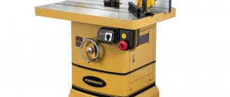
Choosing an Electric Motor for Woodworking Operations
An equally important element of the machine is the engine. The main characteristic that needs to be given enough attention is power. Regardless of the type of motor - single-phase or three-phase, the power can range from 1200 to 2000 W.
Perfectly suited engines:
From a washing machine, if a lathe is needed for small-volume work and the size of the workpiece will not exceed 30–40 cm, in this case the exact maximum length is selected experimentally. Such engines can help in processing small items, dishes, small knobs for stairs and similar interior elements.
Some models of washing machines are equipped with an asynchronous electric motor, in which, by changing the winding, you can step by step change the shaft rotation speed. Similar motors are also installed in floor fans, only there they have a lower power of about 40–100 W. This motor is enough for a mini-machine for small household products.
Homemade folding stand
A very original idea for a folding stand for hand tools. Everyone is in their place. It doesn't take up much space. The design is based on furniture guides. The clamp holds the stand in the upper position. Neodymium magnets prevent instruments from falling out of their stocks. A great idea for DIYers who love to do everything with their own hands.
Impact screwdriver from starter
There are situations when it is impossible to unscrew a rusted bolt or screw with a conventional tool. An impact screwdriver does this job perfectly. The tool is made by hand from parts of a car starter:
- The shaft and bushing are removed from the starter housing.
- Part of the shaft is cut off, leaving a splined rod.
- A piece of pipe of suitable size is placed on the sleeve.
- A piece of bolt of equal diameter is welded to the end of the pipe.
- The end of the shaft is ground into a tetrahedron shape, onto which heads of the required size are placed. For screws, a bit is inserted into the head.
When you hit the head of the bolt with a hammer, the shaft slides with beveled splines inside the sleeve, performing a rotational movement. The stronger the blow, the more force the shaft rotates.
Useful hammer upgrade
When working with a hammer in an inconvenient place, you often have to take nails with you in your pocket or even in your teeth. Agree, this is not very pleasant.
By installing a small but powerful magnet on the hammer handle, you can at least partially solve this problem. The upgraded hammer will carry the nails itself and you can safely work without holding the next nail in your teeth. It's convenient, and your teeth don't get damaged.
Pipe bender
A device for bending metal pipes is a metal rod welded to the frame. I make the rod from a piece of reinforcement. The pipe is placed on a pin, and on the other side a long piece of reinforcement is inserted into the pipe. By pressing the lever, the pipe is bent at the desired angle. The device is suitable for small sections of round pipes.
Making a pipe bender with your own hands
- Two axles are welded to a metal frame from pieces of smooth reinforcement, onto which old car hubs are placed.
- Protruding chamfers are removed from the hubs so that the side surfaces of the rollers are smooth.
- The channel is placed in the opening between the hubs with the shelves facing up.
- The same profile, smaller in width, with the flanges down, is placed into the channel.
- An axle is welded to the top of the inner profile, onto which the third hub is placed.
- A vertical shelf made of steel sheet is welded to the frame.
- A hole is cut in the vertical bar and the bearing is pressed into it.
- A nut is secured to the middle channel by welding.
- One end of the screw rod is screwed into the nut.
- The screw shank is threaded through a bearing in a vertical bar.
- A rotary handle is welded to the shank on the back side of the bar.
- A swing arm is welded to the axis of the drive hub.
The machine is ready for use. A profile pipe is inserted between the rollers and clamped with a screw. The rotary lever drives the rollers, which pull the pipe, bending it. The bending radius is set using the rotary handle of the screw.
A pipe bender made from car hubs is one of the device options. There are many designs of bending devices. In some models, the drive roller is coaxially connected to the motor shaft.