The forging hammer is one of the most specific devices in any forge shop. With its help, workpieces are deformed in hot and cold states, giving them the required shape. Let's look at the operation of this unique equipment, what actions in blacksmithing can be performed with a forging machine, and what the cost of forging operations is.
This information will primarily be needed by those who are currently deciding which forging hammer to buy and how to then use it correctly. It is very important to study their technical characteristics in the models under consideration, in order to then make the optimal choice of equipment using a comparison method.
With the help of blacksmith hammers you can do:
- bending of metal blanks;
- stretching or lengthening of products;
- sewing holes of different diameters in them;
- upset or compression of workpieces;
- chopping workpieces into pieces.
Most types of forging hammers are capable of performing all of the above work; these machines can be easily classified according to their design properties and performance qualities.
Operating principle and varieties
The most successful designs use two types of energy - potential and kinetic. Potential
is determined by the mass of the striker m, the acceleration of gravity g and the height h from which the striker moves down. The implementation of this component alone would lead to an exorbitant increase in the lift height.
In turn, the realized kinetic energy
depends not so much on the mass as on the speed v of the collision with the deformable metal. Thus, the initial parameters should be:
In addition, from the point of view of forging productivity, the number of blows per unit time and the closed plan height are also of great importance (the parameter is important for determining the maximum dimensions of the workpiece that can be placed in the forging space).
Compressed air, steam, and various mechanical devices are used as energy carriers. Not all of the above is suitable for homemade development. Steam, for example, is definitely not suitable, since for this you will have to specially build a boiler station. A number of mechanical systems - belt, chain, board - are also unacceptable due to their high complexity, as well as the need to use scarce and expensive components. In particular, the drive board will require high-quality beech, cedar or ash wood (and even these species will not withstand more than 40...50 hours of operation). Forging hammers with a belt or chain have even greater design complexity.
They will be discussed further.
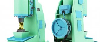
Pneumatic drive structures
Figure-1 Pneumatic version.
Machines can be single or double acting. In the second case, the tool is additionally accelerated due to the increased pressure created by the compressor using a special distribution device - a spool. The spool controls the unit, ensuring the supply of energy into the cavity above the striker.
For homemade production, options with one cylinder, where movement occurs in one cavity, are more suitable. The equipment turns out to be quite simple from a design point of view, and if you have a workshop, it can easily be made with your own hands.
In this case, the cylinder can be open either at the top or at the bottom. (at the location of the compressor piston). The equipment operates as follows.
With the cylinder open at the top, the movement from the electric motor is transmitted to the crank shaft, which is rigidly connected to the compressor piston. The piston, which is connected to the tool by means of a rod, is at this time located below, on the anvil. When the compressor piston moves upward, a vacuum is created under it, which captures the rod and forces it to be carried upward along the guides.
When the crank shaft passes through its upper position, the compressor piston begins to move down and compresses the air that is in the space between the pistons. Energy and stroke are determined by the size of this space, the mass of moving parts and the pressure that the air injection unit creates.
Cylinder circuit
open at the top, somewhat more difficult. It includes:
- Working piston.
- Compressor piston.
- Stock.
- Striker.
- Control lever.
- Connecting rod.
- Crank.
How does it work
With the cylinder open at the top, the compressor piston can slide freely along the rod, working out the trajectory that is given to it by the lever through the crank mechanism. Thus, the stroke will depend not only on the vacuum in the cavity, but also on the weight of the moving parts. This technique has a significant drawback - increased wear of levers, which operate under conditions of constant vibration and sharply changing loads.
The control system for single-cylinder structures is as follows. The control system has two handles. One is designed to reverse the drive of the crank mechanism (however, a control stroke sensor can be installed here). By moving the compressed air handle, you can control the intensity of the impact, since at a certain position of the handle, the volume of the working space - and, consequently, the impact power - is different.
Sequencing
Let's look at a diagram of working with a simple hammer.
- To perform a hold, the operator moves the handle to a predetermined position. Both chambers are filled with air, the striker does not touch the anvil, but the engine does not turn off.
- When the handle is raised, the cylinder and upper chamber are filled with air, and the lower chamber is insulated. First the firing pin rises, and then the firing pin.
- To perform continuous blows, the operator moves the handle to a predetermined position. The cylinder and both compressor chambers are insulated. When the piston is lowered, the firing pin rises or falls. The impact power is adjusted with a handle.
- To perform a single strike, the operator moves the handle to the continuous strike position and returns it to the hold position.
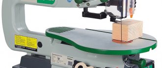
Mechanical drive designs
Of all the varieties, the easiest to make for a forge is a hammer with a lever drive. In mechanical installations, the tool can move both along a circular arc and reciprocatingly.
In its simplest version (without guides, the presence of which for forging ), the unit will include:
Figure 2 - Lever design
How does it work
The circuit operates as follows. The hammer has the ability to rotate around its axis. A lever system is also mounted there, which controls the movements of the hammer.
This system, in turn, is connected with the help of hinges to the connecting rod and, through it, to the crank mechanism, which converts the rotational movement of the electric motor into the reciprocating movement of the connecting rod.
At the opposite end of the system, rubber buffers are installed, which, on the one hand, soften the impact of the hammer on the forging, and. on the other hand, they contribute to the appearance of vibrations that increase the supply of kinetic energy. Thus, the efficiency during continuous operation is slightly higher than during single impacts.
A rubber bumper buffer is fixedly fixed on the frame, which is necessary to dampen constantly increasing vibrations and keep their amplitude in an acceptable range of values.
When you press the pedal, the tension roller pulls the pulley drive belt, after which, when the connecting rod rises up, the hammer will push off from the buffer devices and compress the bumper buffer. It accumulates kinetic energy and gives it to the hammer. When the connecting rod is lowered, the hammer goes down and hits the workpiece. The force of impact and the speed of movement of the hammer depend on the energy parameters accumulated by the hammer. The stroke of the hammer can be changed by shifting the axis in the required direction, for which the guides are intended.
You can change the number of moves in several ways
- By adjusting the pressing force of the pressure roller to the electric motor pulley;
- Changing the gear ratio of the electric motor pulley;
- Using a variator;
- Installation of a DC motor on the drive.
Spring hammers are considered a structural type of lever design. In contrast to the design discussed above, here the role of a device that accumulates vibrations is played by an ordinary car spring.
Design and principle of operation
The working principle of a forging hammer is simple. The hammer hits the forging using a rod connected to the striker.
The standard forging hammer device includes the following parts:
- power cylinder;
- stock;
- side racks;
- shabot;
- drummer “baba”;
- control system.
The power cylinder directs pressure to the lower part with the rod. A striker is attached to it, which makes reciprocating movements. Baba deforms the workpiece. The forging hammer stands compensate for the movement of the striker during impact.
In older machines, the force of the blows was regulated by foot or hand drive. Modern devices operate on different types of energy carriers.
Drawings and assembly instructions
To manufacture homemade equipment, you will need quite a lot of components: a frame, a compressor, a V-belt drive, and a crank mechanism. You can pick up a frame from a small open crank press at Vtorchermet warehouses (for the manufacture of such parts, castings from high-quality steel of type 40GL or 45L according to GOST 977 are usually used, which have a sufficient safety margin for alternating loads).
When selecting a compressor unit, you should focus on models that are capable of creating pressures of at least 4 atm, otherwise the developed energy will not be enough to successfully deform the forgings. From the same considerations, the power of the electric motor and the parameters of the V-belt transmission are selected.
Working principle of a forging hammer
Forging hammers are relevant for small forges that specialize in orders for the manufacture of metal products:
- elements for furniture created by artistic forging;
- small equipment for hunting and fishing;
- memorable souvenirs, etc.
The operating principle of this equipment is based on the use of dynamic impacts of the working body - the rod, connected to the striking part of the machine - the woman, as well as devices for controlling the impact force.
Other required structural elements of a spring forging hammer are described below:
- woman connected to the piston;
- a base fixed to a base;
- a bed with guides for moving units fixed on it;
- drive equipment;
- shield fencing providing the operator with a high level of safety;
- electrical equipment;
- Pneumatic hammers also have a compressor cylinder in their design.
The first models of such equipment were equipped with a foot or hand drive; modern products have a convenient control system that minimizes the effort on the part of the blacksmith.
Let us describe the principle of operation of the device:
- the workpiece is placed in the lower part of the hammer;
- the device is adjusted to the current impact frequency and set in motion;
- when the hammer is activated, the driven upper part of the structure hits the metal workpiece;
- the dynamic impact on the metal workpiece is carried out until it acquires its current shape.
The principle of operation of a diesel hammer is to convert the reciprocating movement, which is performed by the crank mechanism, into a similar movement of the piston. This provides the master with the opportunity to perform many operations with its help.
Design and principle of operation
The functioning of a forging hammer is based on the dynamic impacts of the working body - the rod, connected to the head (the striking part of the machine) and devices that control the force of impact. Other required structural elements are:
- a piston connected to a woman;
- base (fixed on a solid surface);
- bed (guides for moving units are fixed on it);
- drive equipment;
- shield fence (for operator safety);
- electrical equipment;
- compressor cylinder (for pneumatic hammers).
Early machines were either foot or hand driven. A modern forging hammer is equipped with a convenient control system that minimizes the effort of the forge worker.
Rice. 1. Pneumatic hammer device.
(1 - working cylinder, 2 - compressor cylinder, 3 - piston, 4 - crank mechanism, 5 - woman, 6 and 7 - upper and lower strikers, 8 - cushion, 9 - air distribution mechanism, 10 - deformable workpiece)
Briefly, the device works like this:
- the workpiece is placed in the lower part of the hammer (usually the hammer);
- set the device to a certain impact frequency and set it in motion;
- after activating the hammer, the driven upper part hits the workpiece;
- the dynamic effect continues until the workpiece acquires the desired shape.
Types of hammers
According to the type of substance used in the compressor cylinder, the following forging hammers are distinguished:
- steam-air units operate using steam or atmospheric air;
- hydraulic and hydrostatic models use the force of fluid under pressure;
- gasoline hammers operate on the principle of internal combustion engines;
- gas ones use liquefied gas;
- electromagnetic hammers for forging use the energy of electric and magnetic fields;
- mechanical hammers are launched by the physical effort of the master and are used little in comparison with other models of similar equipment;
- spring-spring models work due to the fact that the spring accelerates the fall of the piston down;
- pneumatic ones use the force of gas under pressure during operation.
Separately, it is worth noting the forging pneumatic hammer with a pneumatic cylinder. This structure eliminates the need for the craftsman to use additional energy sources and make the structure heavier. When the forging hammer strikes the workpiece, its shape changes according to the planned working pattern.
Mechanical
A mechanical forging hammer is an old device in terms of its operating principle, developed and put into practice several centuries ago.
The basis of its design is a mechanism that supplies force from the human muscles to the hammer. It was only many years later that the first models with water and steam powered drives were designed.
The main working part of a mechanical hammer is constructed of a lever with a hammer on one side and a massive counterweight on the other. It is installed on a shaft that can swing under the influence of a pedal or lever.
However, it is worth remembering that the efficiency of such equipment in comparison with more modern models is quite low. And the dimensions of the mechanics are quite impressive, which does not allow them to be used in tiny forges.
Pneumatic
A pneumatic forging hammer is classified as forging equipment that is capable of performing a large range of operations, including twisting, cutting and forming metal blanks.
Hammers are installed in single quantities and are equipped with an individual compressor unit. They are not characterized by a large mass of falling parts, therefore they can be used for forging small-sized products.
Often, an air hammer is equipped with a C-shaped frame, fastened together for rigidity by means of side posts. The stamping area of the pneumatic hammer is open on three sides, which greatly simplifies its maintenance.
The pneumatic forging hammer is controlled using a hand lever or pedal and can be used in two directions:
- for artistic forging, units whose weight does not exceed 75 kg are suitable;
- in production: MPCh 150-2000 kg.
The advantages of equipment of this type are as follows:
- energy intensity;
- high sensitivity when adjusting operating modes;
- simple controls;
- long service life.
The disadvantages of pneumatic hammers are decent dimensions, significant weight, and difficulty in transportation.
Markings and standard sizes of forging hammers
The main technological parameter for choosing the standard size of a forging hammer is its mass of falling parts (MPH). In accordance with the departmental standard KN-01-1, the designation of forging hammers is combined, digital and alphabetic, and has the form МАХХХХ. The letter "M" stands for "hammer". The first two digits could be as follows:
- 13 – for forging double-action steam-air hammers of arch type;
- 15 – for bridge-type double-action steam-air forging hammers;
- 21 – for double-action steam-air stamping hammers;
- 41 – for forging pneumatic hammers.
The specified equipment is manufactured in accordance with the requirements of GOST 9752 (forging hammers), GOST 7024 (steam-air stamping hammers) and GOST 712 (pneumatic hammers). The standard range for the MPH parameter is considered to be a nominal size range of numbers, therefore the last two digits of the designation in the hammer brand indicate specifically the power of the equipment:
| The last two digits of the designation | 27 | 29 | 32 | 34 | 36 | 40 | 43 | 45 | 47 | 49 | 50 | 52 |
| Mpch, kg | 50 | 80 | 160 | 250 | 400 | 1000 | 2000 | 3150 | 5000 | 8000 | 10000 | 16000 |
| Impact energy. kJ | 0,9 | 1,55 | 3,3 | 6,45 | 11 | 30 | 50 | 80 | 125 | 240 | 310 | 400 |
Additional letter designations are also possible, which indicate the modernization of the basic model of the forging hammer.
Forging hammers of other types are rarely used and are manufactured on special orders.
Homemade hammer: super hammer
It will be easier to make a homemade blacksmith hammer for forging metal products if you divide all operations into several stages in the following sequence:
- preparing the base for installation of a forging hammer;
- designing a machine frame with springs;
- assembly of the working mechanism;
- installation of a homemade device.
But before detailed instructions indicating how to make a blacksmith hammer, it should be noted the importance of creating a drawing of the future design.
You can make a forging hammer with your own hands in a workshop or garage. But before work, it is important to determine the current dimensions of the unit, describe all its component parts, which will subsequently make it possible to determine the weight of the product and its functionality.
To do this, you will need to draw up yourself or find on the Internet drawings and an assembly diagram of such a structure with a detailed description of all its parts.
After creating the drawing, the forging devices proceed to forming the foundation. A homemade forging hammer must be installed on a flat area prepared in advance. This is necessary for the normal operation of the device and eliminating the risk of it tipping over during operation.
At the site where the structure will be installed, you need to dig a hole of the current size. Its bottom is carefully sprinkled with sand and crushed stone, watered and compacted. A reinforcing frame is mounted on top of the completed layer of sand cushion, for which reinforcement with a diameter of 12-14 mm is used.
It is extremely important not to forget about dressing, which is carried out every 250-300 mm.
Choosing a method for deforming hot metal
Free forging of small-weight products can be realized on the following forging machines:
- pneumatic hammer with electric drive;
- manual mechanical hammer (with a solid/flexible rod or spring version);
- screw hammer.
The latter option is characterized by the lowest speed of movement of moving parts, and therefore can only be used for forging highly plastic metals. All that remains is to make either a pneumatic hammer or a simple-action mechanical hammer.
Diagram of a forging hammer with a foot drive
Comparing the technological indicators of deformation, it is easy to come to the conclusion that the impact energy for a spring hammer is significantly lower than for a pneumatic hammer. In addition, the presence of el. control in the latter case will significantly reduce physical activity.
In contrast to the pneumatic hammer, the spring version does not require significant initial costs, and is also safer to use. Such a unit does not require electricity. motor, and this will make it possible to subsequently save on energy resources.
The main questions on how to make a homemade blacksmith hammer are discussed below.
We make a pneumatic hammer
The capabilities of this equipment will be determined by the design of the compressor, which will supply the air distribution mechanism with energy.
In this case, a set of drawings should be developed regarding the following components:
- bed (it is better to design a forging hammer with your own hands with a welded bed);
- a working cylinder selected according to the desired impact energy;
- rod;
- pipelines;
- control systems;
- Shabota.
On the Internet you can find suitable drawings of an electric pneumatic hammer. drive. If they are not there, then design is carried out in the following sequence:
We select a compressor: the compressed air consumption should be approximately 5...6 times greater than the volume of the working cylinder. This, in turn, depends on the required pressure on the metal. For example, for steel it must be at least 30 MPa, therefore, the minimum diameter of the rod is 120...150 mm, with a stroke of 150...200 mm (a further increase in the stroke, of course, will increase the kinetic energy, but at the same time it will also cause a significant increase in the height of the equipment). Therefore, the compressed air pressure must be at least 6 at; it will increase if the compressor is located at a distance from the forging unit, since in this case there will be losses of compressed air in the pipelines.
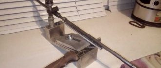
Seal of the rod and piston of the hammer compressor MA4129
Seal of the rod and piston of the hammer compressor MA4129
- women's axle box
- compressor axle box
- crackers and segments
- guide bar
- spring
- ring sealing
- expander
"a" - gap
The wheel is secured against rotation by guide bars 4, mounted in its axle box (Fig. 3). To seal the female rod, an annular recess is made in axlebox I, in which segments and crackers 3 are mounted, tightened by spring 5: As the female rod, as well as crackers and segments wear out, the gap “a” decreases, but can be restored by filing the ends of the segments. To seal the compressor piston rod, an annular recess is made in the compressor axlebox, in which an o-ring 6 is mounted, made of LAM1 material, tightened by an expander 7.
Making a mechanical hammer
The most affordable design is a spring-type mechanical hammer: it is compact and can be quite productive: electric. the drive can provide up to 200...300 strokes per minute.
A homemade spring-type forging hammer with an electric drive consists of:
- Email engine that controls the rotation of the crank shaft.
- An actuator for producing oscillations.
- Springs (use automobile springs, which do not have cracks or delaminations of the metal).
- Striker with a system of guide elements.
- T-type beds.
- The chabot or bottom plate where the actual forging is done.
General view drawing of a homemade forging hammer
Download drawings of a spring-spring hammer
Hand Mechanical Hammer with Board/Belt Includes:
- Two racks closed at the top with guide grooves.
- Striker with a seat for the transmitting element.
- Shabota.
- Lifting mechanism with a lock (you can use a regular ratchet from the locking devices of lifting winches).
- A belt or board that is connected from above to the striker (the board material is usually oak or larch).
Equipment drawings are usually indicated in relation to its actual performance and power, so it is best to select the optimal mass after manufacturing all other components.
The assembly sequence of a mechanical hammer is as follows. To the output end of the shaft el. engine is connected (possibly with a coupling) to the end of the crank mechanism shaft. Next, using a lever, a spring is attached to it, which should have an oscillation in the supports. The striker is pivotally attached to the spring, after which the guides are adjusted (the fit in the hole should provide a gap of at least 1.0...1.5 mm).
At the final stage, the action of the crank assembly is checked and, if necessary, the free vibrations of the spring are reduced (by tightening its fastening in the supports).
Making a homemade forging hammer is not so difficult if you carefully work out the drawings in relation to the specific conditions of using forging equipment.
Download information on other hammers:
If you find an error, please select a piece of text and press Ctrl+Enter.
Source: stankiexpert.ru