In almost all areas of electrical installation work, modeling, robotics, and radio electronics, current-carrying wires are used as a connecting element of an electrical circuit.
Among the huge variety of connection methods to obtain high-quality electrical contact, soldering, terminal crimping, bolting, and sleeve crimping can be performed. But not a single contact can maintain electrical parameters for a long time without first covering the conductor with a layer of tin. Therefore, in this article we will look at how to tin wires and why this procedure is performed.
Why Tinning Wires Is So Important
Tinning wires prevents them from oxidizing
Before tinning a wire, you need to know why this procedure is so necessary. Copper and aluminum, when interacting with oxygen, oxidize, forming an oxide film on their surface, which impairs conductivity and increases resistance. Tinning the wires avoids this. Wires are tinned with lead-tin solders; their advantage is a long service life, safety and reliability.
Tinning is also used during soldering, for example, when connecting LED strips to a power supply. If the wires of the lighting device are not tinned first, over time all the wires will fall off.
Characteristics
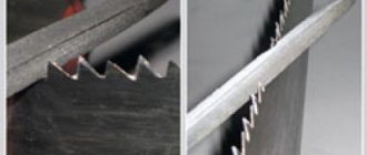
The main distinguishing feature between them is the ability to bend. The diameter of tinned copper and aluminum can differ significantly. The most widely used wire is the one whose diameter is in the range of 0.02-9.42 mm.
To make it, use ordinary copper wire on a reel, subjecting it to galvanic tinning. The material is passed through a tin bath containing molten tin. To prevent it from entering into oxidation with oxygen in the air, the surface of the bath is covered with substances that cannot allow air to pass through. In particular, such a substance may be charcoal.
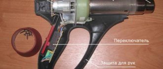
Tinning wires with a soldering iron
Tinning wires with a soldering iron
To do the job well, it is important to be confident in using a soldering iron. If there are no established skills, you will not be able to tin and solder the wire.
There are different models of soldering irons, each with its own technical characteristics - power, dimensions, etc. It is recommended for a novice master to give preference to soldering stations where it is possible to regulate the heating temperature independently.
It is advisable to purchase an expensive device, since the process will take less time and the work will be done with joy.
Fine soldering
Soldering printed circuit boards has its own peculiarities. How to solder parts onto printed circuit boards, in general, see the small master class in the drawings. Tinning of wires is no longer necessary, because the terminals of the radio components and chips are already tinned.
In amateur conditions, firstly, there is little point in tinning all current-carrying paths if the device operates at frequencies up to 40-50 MHz. In industrial production, boards are tinned using low-temperature methods, for example. spraying or galvanic. Heating the tracks along their entire length with a soldering iron will worsen their adhesion to the base and increase the likelihood of delamination. After installing the component, it is better to varnish the board. This will immediately darken the copper, but this will not affect the performance of the device in any way, unless we are talking about microwaves.
Soldering radio-electronic components onto a printed circuit board
Then, look at the ugly thing on the left of the trail. rice. For such a marriage, and in the bad memory of the Soviet MEP (Ministry of Electronic Industry), installers were demoted to loaders or helpers. It’s not even a matter of appearance or excessive consumption of expensive solder, but, firstly, the fact that during the cooling of these plaques both the mounting pads and the parts overheated. And large heavy influxes of solder are rather inert weights for already weakened tracks. Radio amateurs are well aware of the effect: if you accidentally push a “cuttlefish” board onto the floor, 1-2 or more tracks peel off. Without waiting for the first re-soldering.
Incorrectly and correctly soldered circuit boards
Solder beads on printed circuit boards must be round and smooth with a height of no more than 0.7 times the diameter of the mounting pad, see on the right in Fig. The tips of the leads should protrude slightly from the beads. By the way, the board is completely homemade. There is a way at home to make a printed edit as accurate and clear as a factory one, and even display the inscriptions you want. White spots are reflections from the varnish during photography.
Swellings that are concave and especially wrinkled are also a defect. Just a concave bead means that there is not enough solder, and a wrinkled bead means that air has penetrated into the solder. If the assembled device does not work and there is a suspicion of a faulty connection, look first in these places.
ICs and chips
In essence, an integrated circuit (IC) and a chip are the same thing, but for clarity, as is generally accepted in technology, we will leave the “microchip” microcircuits in DIP packages, up to and including large ones in terms of the degree of integration, with pins separated by 2.5 mm, installed in mounting holes or soldering pins if the board is multilayer. Let the chips be ultra-large “million-dollar” ICs, mounted on the surface, with pin pitches of 1.25 mm or less, and the microchips – miniature ICs in the same cases for phones, tablets, and laptops. We do not touch processors and other “stones” with rigid multi-row pins: they are not soldered, but installed in special sockets, which are sealed into the board once when it is assembled at the enterprise.
Soldering iron grounding
Modern CMOS (CMOS) ICs are the same in sensitivity to static electricity as TTL and TTLSh, holding a potential of 150 V for 100 ms without damage. The amplitude value of the effective network voltage is 220 V - 310 V (220x1.414). Hence the conclusion: you need a low-voltage soldering iron, for a voltage of 12-42V, connected through a step-down transformer on the hardware, not through a pulse generator or capacitive ballast! Then even a direct test on the tip will not ruin expensive chips.
There are still random, and even more dangerous, surges in mains voltage: welding was turned on nearby, there was a power surge, the wiring sparked, etc. The most reliable way to protect yourself from them is not to remove “stray” potentials from the soldering iron tip, but not to let them escape from there. For this purpose, even at special enterprises of the USSR, the circuit for switching on soldering irons was used, shown in the figure:
Grounding diagram for a low-voltage electric soldering iron
The connection point C1-C2 and the transformer core are connected directly to the protective grounding loop, and the screen winding (an open turn of copper foil) and the grounding conductors of the workplaces are connected to the middle point of the secondary winding. This point is connected to the circuit with a separate wire. If the transformer has sufficient power, you can connect as many soldering irons as you like to it, without worrying about grounding each one individually. At home, points a and b are connected to a common ground terminal with separate wires.
Microcircuits, soldering
Microcircuits in DIP packages are soldered like other electronic components. Soldering iron – up to 25 W. Solder – POS-61; flux - TAGS or alcohol rosin. You need to wash off its remains with acetone or its substitutes: alcohol takes the rosin hard, and it is not possible to completely wash it off between the legs either with a brush or a rag.
As for chips, and especially microchips, soldering them manually is strongly not recommended for specialists of any level: this is a lottery with very problematic winnings and very likely losses. If it comes to such subtleties as repairing phones and tablets, you will have to fork out for a soldering station. Using it is not much more difficult than a hand soldering iron, see the video below, and the prices of quite decent soldering stations are now affordable.
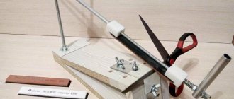
Required Tools
The flux is chosen depending on the material of the wire
. Installation, modernization, repair and maintenance of wires is a troublesome task, but not difficult. To reduce the time spent, pre-prepare all the necessary tools and consumables for the job. The list looks like this:
- consumables include solder and flux;
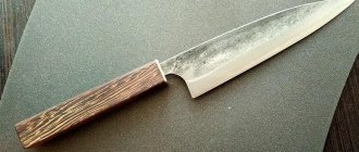
- sharp knife;
- soldering station or soldering iron;
- technical or medical tweezers;
- ordinary pliers.
You can use not a well-sharpened knife, but special pliers that allow you to remove the entire insulating layer with a few movements. But their cost is quite high, so many people use a knife or scalpel.
In each case, a certain solder and flux composition for the cables is required, this must be taken into account.
How to solder pipes
Copper pipes are soldered using a high-temperature method with any hard copper solder with activated flux paste, which does not require removal of residues. Next, there are 3 options:
- In copper (brass, bronze) couplings - soldering fittings.
- With full distribution.
- With incomplete distribution and compression.
Soldering copper pipes into fittings is more reliable than others, but requires significant additional costs for couplings. The only case when it is irreplaceable is a drainage device; then a tee fitting is used. Both soldered surfaces are not tinned in advance, but are coated with flux. Then the pipe is inserted into the fitting, securely fixed and the joint is soldered. Soldering is considered complete when the solder stops going into the gap between the pipe and the coupling (0.5-1 mm is needed) and protrudes outward as a small bead. The fastener is removed no earlier than 3-5 minutes after the solder has hardened, when the joint can already be held by hand, otherwise the solder will not gain strength and the joint will eventually leak.
How pipes with full distribution are soldered is shown on the left in Fig. The “distributed” soldering holds the same pressure as the fitting one, but requires additional pressure. special tools for unrolling the socket and increased solder consumption. Fixing the soldered pipe is not necessary; it can be pushed into the socket with a twist until it jams tightly, so soldering with full distribution is often done in places that are inconvenient for installing the clamp.
Soldering copper pipes
In home wiring made from thin-walled pipes of small diameter, where the pressure is already low and its losses are insignificant, soldering with incomplete expansion of one pipe and narrowing of the other may be advisable, pos. I on the right in Fig. To prepare the pipes, a round stick made of hard wood with a conical tip of 10-12 degrees on one side and a truncated-conical hole of 15-20 degrees on the other, pos. II, is sufficient. The ends of the pipes are processed until they fit into each other without jamming for approx. by 10-12 mm. The surfaces are tinned in advance, more flux is applied to the tinned ones and they are connected until they jam. Then they heat until the solder melts and prop up the narrowed pipe until it jams. Solder consumption is minimal.
The most important condition for the reliability of such a joint is that the narrowing must be oriented along the flow of water, pos. III. Bernoulli's school law is a generalization for an ideal fluid in a wide pipe, and for a real fluid in a narrow pipe, due to its (liquid) viscosity, the maximum pressure jump shifts opposite to the current, pos. IV. A component of pressure force arises, pressing the narrowed pipe against the distributor, and the soldering turns out to be very reliable.
Procedure
To tin the wire, you need to follow the following algorithm:
- Using a special tool, a knife or scalpel, remove the insulating layer from the wires that need to be connected.
- After removing the insulating material, clean the current-carrying conductors until a characteristic shine is formed. To do this, you can use a knife or sandpaper. If the work is to be done not with a cast core, but with a stranded wire, each wire is fluffed up and stripped separately.
- The soldering iron is plugged into the outlet and cleaned of all the contaminants that it likes to collect, especially old solder and dust. When cleaning the soldering iron wire, it is recommended to use light sandpaper.
- The tip of the wire needs to be heated. This can be done using a soldering iron, a gas torch or a regular lighter.
- When the soldering iron has warmed up to operating temperature, its core is touched to the solder and rosin. The working surface should be generously covered with melted tin.
- The next step is to touch the copper conductor with a hot soldering iron. The solder should be evenly distributed throughout the core. To apply solder, pliers and tweezers are used.
- At the end of the work, the cable or wire is carefully inspected. The working surface must be completely and evenly covered with solder. There should be no empty cavities or accumulations of substance. If shortcomings are found in the work, the procedure is repeated.
If you have to work with very thin wires, it is better not to use rosin, since it is very difficult to calculate the exact amount of the substance. Soldering acid is suitable as an analogue. You can treat the tip of the conductor with an ordinary brush. After this, you can begin applying solder. This method cannot be called more reliable, but with these types of wiring it is impossible to do otherwise.
The process of preparing a copper tip
The coating process is straightforward. Molten solder fits well on hot copper, but with one condition - it must be clean. This can only be achieved at low temperatures. Oxidation accelerates with increasing temperature and adhesion disappears. Cold solder cannot be stuck to the tip because it does not melt. It turns out to be a vicious circle.
Slag, rosin and plastic residues, scale and other debris can be removed using a cold tool. The rod is pulled out before this operation so as not to damage the heater. The tip inside the heater also oxidizes, which impairs heat transfer. Electricity due to scale overcomes excess resistance and is wasted.
Before tinning a soldering iron with a copper tip, it must be cleaned of dirt. This is done with a file or sandpaper. The material should be sharpened to a clean finish to ensure it looks like new. It's easier to do this with sandpaper. The surface is polished to a smooth state - this way oxidation occurs more slowly.
The rate of oxidation can be reduced by shackling the tip. This is done with a hammer on an anvil. Using gentle blows, the surface is strengthened and the copper rod is shaped. Next they move on to the tinning process until it is covered with slag.
Methods for tinning a copper tip:
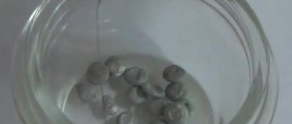
- Rosin. The method is smoky, so it is difficult and dangerous to health to carry out in a residential area. It's better to use the balcony. The cleaned base is immersed in a jar of rosin and a little solder is placed there. It will instantly cover the sting and prevent it from oxidizing. After the procedure, the tip of the sting is wiped with thick natural cloth, but carefully so as not to burn your fingers. The solder will rub into the copper. The procedure is performed after long-term storage of the soldering iron.
- A method of rubbing a surface with tin. The clean base is slightly warmed up and dipped in rosin. Then the surface is rubbed with tin. The procedure is repeated several times. The protective layer is secured by rubbing against cloth. The result can be obtained without smoke in any room.
Proper preparation will allow you not to be nervous at the initial stage of work. After a while, the process needs to be redone because the copper begins to oxidize.
Wire processing methods
Tinning with a wooden block
There are several ways of tinning. Some craftsmen prefer a method, the essence of which is to press the wires with a soldering iron to a flat wooden surface.
When heated, wood releases gases that act as flux, helping to remove oxides from the metal.
It is possible to remove the oxide film on the surface of conductive wires more efficiently using aspirin. During operation, the tablet is placed under the wires. When heated, acetylsalicylic acid releases gases that envelop the joint, displacing impurities that negatively affect the quality of the joint. This simple and inexpensive method provides high-quality tinning.
There is another way to prepare multi-core cables and wires in which the copper base is coated with enamel. It is preferable to use a small piece of PVC material as a substrate. When exposed to heat, polyvinyl chloride begins to actively release hydrogen chloride, which effectively destroys the oxide layer.
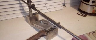
Distinctive Parameters
Tinned copper has high ductility and can be easily machined. It is this material that is used in electrical engineering for the manufacture of conductive cores of copper cables and braiding for military and civil products.
Let's try to find out the difference between tinned and untinned copper. The first option is more protected from external influences, since the wire is coated with a layer of tin. This metal protects the metal thread from any manifestations of corrosion, giving the material increased tensile strength. Tinned copper does not break when bent.
Tinning by dipping
If you have to work with wires and cables of large diameter, then it is advisable to carry out the preparation differently. In this case, complete and uniform distribution of solder is not easy to achieve.
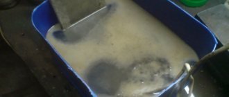
There is a special device - a crucible, into which small pieces of tin are placed. There they heat up, resulting in molten metal. The end of the wire is first immersed in rosin or other types of flux, and then in the crucible container. This approach ensures complete and uniform distribution of substances at the cut site.
This method can only be used with fully tinned wires. Immersion is already on a completely different scale, and is carried out in industrial conditions. The process is implemented using a special coil with wound wire. First, the entire copper surface is manually processed with hard brushes; their bristles are first treated with liquid zinc chloride. Dissolved flux is obtained from a mixture of technical hydrochloric acid and zinc.
Next, the wire from the coil begins to slowly unwind and is dipped into a container filled with dissolved tin. The uniformity of the coating is ensured by secondary processing of the cable or large-diameter wire with rubber brushes. Finally, the cable is immersed in a container of cold water and brushed again. After this, the wires and cables are wound and packaged for further sale in hardware stores.
Features of coatings
Simple type soldering irons traditionally have a copper tip. The material is still used since the invention of the tool due to its high heat-conducting properties. But there is a drawback - the ability to undergo high wear. The copper burns out or dissolves in the solder. The deficiency needed to be eliminated, and manufacturers began to apply additional nickel or silver coating.
Nickel is highly durable and does not wear out. Long service life is an advantage of nickel plating. Disadvantage: poor adhesion. This tip does not hold solder well. Soldering can only be done by applying solder directly to the work area. The working area is heated with a tip, then a small amount of solder or solder paste is placed. Setting occurs due to heat.
Silver has good adhesion, but conducts heat poorly. In addition, the material is expensive. Over time, the silver wears away and exposes the copper base. This occurs because the silver coating dissolves into the solder.
The characteristics of spraying complicate operation and maintenance. Therefore, radio amateurs, especially the older generation, prefer copper soldering irons. But the copper tip has a drawback - hot copper instantly oxidizes. Interaction with air occurs only on a thin layer, but this is enough for zero adhesion. Heat is also transferred worse. The way out of this situation is to always cover the tip with a thin layer of solder .
Tin cannot be applied before soldering, as the copper underneath will begin to burn out. At the site of burnout, slag appears, due to which there is no adhesion. The master begins to be distracted from work.
Abrasive materials wear down the coating. Nickel or ceramics are applied in a thin layer to the tip - that is why they cannot be ground off. The expensive tip will turn into a copper rod.