The cantilever vertical milling machine model 6Р12 (6Т12) is used for a variety of work on workpieces made of metal and other materials. Technological capabilities make it possible to process horizontal, vertical and inclined planes, as well as various grooves and angles.
6Р12 (6Т12) machines are used in main production shops, repair areas, and training workshops.
Marking:
- 6 — milling group;
- P - indicates the generation of the machine;
- 1 - with a vertical spindle;
- 2 - characterizes the parameters of the working plane of the table 300x1250 mm;
- F1 - equipped with a digital display;
- F3 - CNC.
Similar models: 6М12П, 6Б12, 6Л12, 6Н12, 6Р12Б, 6Р12К, FSS350MR.
Design features
- Overload protection system.
- The high drive power and rigidity of the equipment allow the use of carbide tools, which are various cutters: end mills, face mills, disk mills, as well as drills, reamers, countersinks.
- Setting up automatic modes allows you to integrate the equipment into production lines.
- Large limits of spindle speeds and feeds.
- The use of additional accessories and devices significantly expands the technological capabilities.
- The workpiece is installed and secured in a machine vice or directly on the table.
- All guides are hardened and ground.
- The supply of coolant to the cutting zone reduces tool wear and heat during milling.
- Vibration resistance increases the accuracy of the resulting product.
- Using a copying device, it is possible to process curved planes.
- Mechanized mounting of the cutting tool inside the spindle.
- Ease of operation and maintenance.
- Normal accuracy according to GOST 8 - 77.
Application and description of the 6T12 milling machine:
various milling operations on metal, vertical milling, at various angles. Operated in semi-automatic mode, the work table feeds are mechanical. The 6T12 machine has proven itself well in primary production at large machine-building enterprises. Accuracy class - N and P, according to GOST 8-82. The milling head performs vertical operations, can be rotated in both directions, for working at different angles. The productivity of the 6T12 milling machine can vary from single and small-scale, for example, in repair shops, to medium-scale, in industrial production, all movements of the table and tool are mechanized.
Machine connection
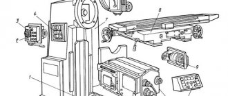
Before connecting the machine to the power supply, connect the machine to the workshop grounding system 4 (Fig. 1)
The cable supply from the workshop electrical network to the input terminals of the machine is made through cover 5 on the top wall of the control station. The cross-section of the cable cores (wires) is determined by the rated current of the machine and the rated current of the input switch release indicated on plate 1.
ATTENTION! The machine must be reliably grounded in accordance with the rules and regulations.
IT IS PROHIBITED TO WORK ON THE MACHINE WITH THE CONTROL CABINET AND TERMINAL BOX OPEN. PREVENTIVE REPAIRS, INSPECTION AND CLEANING OF ELECTRICAL EQUIPMENT ARE TO BE PERFORMED ONLY WHEN THE POWER SUPPLY NETWORK IS DISCONNECTED.
The electrical resistance measured between the ground screw and any metal part of the machine that may become live as a result of insulation breakdown should not exceed 0.1 ohm.
Maintenance of the electrical equipment of the machine must be carried out by specialists in the electrical equipment of machine tools.
Remember that when the input switch is turned off, its upper terminals and the input terminal set are under mains voltage. DO NOT remove covers.
For inspection and adjustment of electrical equipment under voltage (with the cabinet door open), the circuit provides a release switch SA1 installed in the control cabinet. This switch must be used by qualified electricians.
Main types of work of the vertical milling machine 6T12:
— vertical milling of flat, stepped, curved surfaces
— roughing and finishing operations, the rigidity of the structure allows you to install heavy parts without loss of accuracy and productivity
- milling and drilling work at various angles, due to tilting the head
— processing of grooves, wheels, horizontal surfaces of parts
— drilling, boring work, with automatic tool feed, through drilling and against the stop
— thread cutting in semi-automatic mode, fine tuning of feed.
Kinematic diagram
The main task of the kinematic diagram is for the owner to understand how the main elements of the equipment interact and contact each other. The callouts include the number of gear teeth. The main movement is made possible by a flanged electric motor via an elastic coupling. The number of revolutions can be changed due to the movement of three gear blocks along special splined shafts.
The feeders are driven by a flanged electric motor mounted in the console. Thanks to two three-crown blocks and a movable gear, access to 18 different feeds is provided, which are transmitted to the console via a ball overload clutch.
Obtaining accelerated movements becomes possible when high-speed clutches are turned on, which rotates thanks to intermediate gears from an electric feed motor. The main element of the entire structure of the machine is the bed, on which other mechanisms and components are fixed. It is rigidly attached to the base using a set of pins.
Modifications of the 6T12 cantilever milling machine:
— vertical cantilever milling machine 6T12. Accuracy class N according to GOST. The kit includes a rotating milling head and a control panel on a rotating bracket.
— milling machine 6T12P. It has an increased accuracy class and can be equipped with a digital display device.
— milling machine 6T12-K with cabinet protection of the processing area. Sliding screens are installed on the work table to reduce the noise of the machine and the splashes from coolant and chips coming out.
Vertical cantilever milling machine 6T12 price – 1,774,000 rubles.
The machine is new, 1 year warranty, pre-sale preparation.
How does the rotating head of the machine work?
The image above shows the current drawing of the rotary head, which is used in the 6T12 machine. It is centered in the annular recess located in the neck of the frame, secured with 4 bolts that fit into 1 different groove of the frame flange.
The spindle consists of a double-bearing shaft, which is integrated into the sliding sleeve. Adjusting the axial play comes down to the need to grind rings 4 and 3. Elimination of increased play in the front bearing becomes possible by tightening the nut and grinding ring 5. The owner is required to follow the correct maintenance procedure. To get rid of the radial play, the value of which is one hundredth of a millimeter, a grinding of approximately 0.12 millimeters is required.
Design and operating principle of the 6T12 vertical milling machine:
performs all types of milling and drilling work, the working dimensions of the table 320x1250mm allow you to reliably install and process a workpiece of the appropriate size, the milling machine allows you to process small and medium-sized workpieces up to 450mm in height. Thanks to the rigid design of the 6T12 vertical milling machine and a powerful electric motor, it is possible to produce parts with complex shapes, such as molds, cams, dies from various alloys. The vertical milling head of the 6T12 rotates 45 degrees, which allows you to process surfaces at an angle and a curved shape. Also, to process long workpieces, the spindle head itself moves on a retractable trunk. The console of the 6T12 vertical milling machine allows the work table to move vertically; if necessary, the operator can turn on, in addition to manual, automatic feed of the table in the vertical, transverse and longitudinal directions. You can expand the technological capabilities with the help of convenient devices - rotary tilting tables, dividing heads of different diameters, rotary vices, all equipment can be installed and fastened into T-shaped holes, of which there are 3 on the work table. Drawings of mounting and connecting dimensions, dimensions of the working space are sent upon request.
Price
You can find out detailed information and buy a vertical milling machine 6P12 (6T12) by contacting us by phone +7 (4852) 66-40-25 , through the request form on the website, or by email: This email address is being protected from spam bots. You must have JavaScript enabled to view. We will provide a detailed commercial offer as soon as possible. Delivery time and price depend on the design and configuration. We provide a 12 month warranty on new machines. Under an additional agreement, we carry out transportation and commissioning at the customer’s premises.
Design and principle of operation of the 6T12 vertical cantilever milling machine:
the machine has a powerful main movement drive, 7.5 kW, which allows you to mill parts from difficult-to-cut alloys. The table is fully mechanized and has automatic feeds under all three axes. To increase productivity, the machine has a reverse accelerated table speed. Additionally, the 6T12 milling machine can be equipped with a mechanism that controls the slowdown of the table working speed depending on the feed size. The tool is mechanically secured in the spindle. To switch speeds without stopping the machine and, if necessary, completely braking it, the vertical cantilever milling machine is equipped with a modern electromagnetic clutch. For serial processing of parts on a 6T12 vertical milling machine, automatic and semi-automatic machine cycles are used. Upon request, our technical department will send instructions for connecting to electrical power and a foundation plan. Each milling machine we supply has an inventory number; together with a warranty card and a certificate of conformity, this is proof of quality. The 6T12 vertical cantilever milling machine is a reliable machine with a service life of 15 years.
Exploitation
To increase operating efficiency, each machine is equipped with a set of auxiliary circuits - bearings, slings, lubrication, kinematics, and so on. The rest of the manual includes electrical equipment. Here is a schematic diagram for connecting electrical appliances, as well as a set of specifications for selecting spare parts.
Based on statistical data obtained during the long-term production of the machine, the manufacturer has compiled a list of wearing parts. For them, a separate drawing of each element is provided. Thanks to unification, it becomes possible to use spare parts from other series of 6T machines, including 6T13.
Technical characteristics of the vertical milling machine 6T12:
| Work table dimensions, mm | 1250x320 |
| Mechanical movement of the table: | |
| — in the longitudinal direction, mm | 800 |
| — in the transverse direction, mm | 320 |
| — in the vertical direction, mm | 420 |
| Weight of the workpiece installed on the table, kg. | 630 |
| Rotation of the vertical head, gr. | ± 45 |
| Machine spindle | 50 |
| Division of the dial when moving, mm | 0,05 |
| Mechanical feed of the machine table: | |
| — with longitudinal movement, mm/min | 12 – 1600 |
| — in transverse movement, mm/min | 12 – 1600 |
| — in vertical movement, mm/min | 4 – 530 |
| Accelerated table speed: | |
| — with longitudinal movement, m/min | 4,0 |
| — in transverse movement, m/min | 4,0 |
| — in vertical movement, m/min | 1,3 |
| Main electric motor power, kW | 7,5 |
| Tool rotation speed, rpm | 31 – 1600 |
| Operating network voltage, V | 380 |
| Table grooves, pcs. | 3 |
| Accuracy class according to GOST 8-82 | N, P |
| Dimensions 6T12, m | 2.3x2x2.2 |
| Weight 6Т12, kg | 320 |
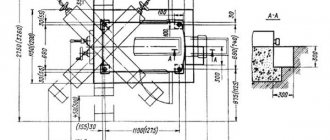
How to install 6T12
Installation of the machine is allowed on a special foundation or on a concrete floor, the thickness of which must be at least 300 mm. Such measures are justified. After all, the weight of the equipment is 3250 kg. Only if the requirements for the installation of the machine are met, the manufacturer guarantees quiet and accurate operation of the equipment. When arranging the foundation, it is necessary to provide wells for anchor bolts and a pit where the coolant from the base of the frame will drain.
The machine on the foundation must be aligned with steel wedges, then the cement solution must be added, and after it hardens, the frame must be secured with foundation bolts.
Special requirements apply to grounding installation and voltage supply. You need to familiarize yourself with them in the operating instructions, which are necessarily supplied with the 6T12.
Instructions for servicing electrical equipment
Reliability and durability of the electrical equipment of the machine is ensured by proper operation and proper care.
Systematic technical inspections and cleaning of electrical equipment from contamination are mandatory.
Carry out technical inspections of magnetic starters, relays and protection devices at least once a month. During inspections, pay special attention to the correct functioning of the moving parts of the devices, the reliability of the removable contact connections and the fastening of the devices. Check the contact systems of electrical devices, if necessary, remove carbon deposits and adjust.
Carry out technical inspections of manual control devices, transformers, capacitors, resistors and other fixed devices at least once every six months. During inspections, check the reliability of the fastenings and the condition of the grounding circuits. For transformers, check the winding resistance value, which should be at least 0.5 Megohm, measured with a megger at a voltage of 1000 V.
The frequency of inspection of electric motors is set depending on production conditions, but not less than once every two months. When inspecting electric motors, it is necessary to clean them from contamination, check the reliability of grounding and connection to the drive mechanism.
The frequency of preventive repairs of electric motors is established depending on production conditions, but at least once a year or 4000 hours of operation. During preventive maintenance, the electric motor is disassembled, internally cleaned and the bearings are replaced with grease. Before filling with fresh lubricant, the bearings must be washed with gasoline, and the chamber must be filled with fresh lubricant to 2/3 of its volume. Recommended bearing lubricants are given in Table 8.
The electrical circuit diagrams of the machine are shown in Fig. 2, 3.
Electrical connection diagrams of the machine, console, main console, and control station are shown in Fig. 4…7.
Electrical equipment of milling machines of the Gorky Machine Tool Plant, GZFS
Electrical equipment of milling machines 6T12, 6T13, 6T82, 6T82G, 6T82Sh, 6T83, 6T83G, 6T83Sh
Electrical equipment of milling machines 6T82G-29, 6T82-29, 6T12-29, 6T82Sh-29, 6T83G-29, 6T 83-29, 6T13-29, 6T83Sh -29
Electrical equipment of milling machines 6P12, 6P13, 6Р82, 6Р82Г, 6Р82Ш, 6Р83, 6Р83Г, 6Р83Ш, 6Р12Б, 6Р13Б
Electrical equipment of milling machines 6M12P, 6M12PB, 6M13P, 6M13PB, 6M82, 6M82Sh, 6M82GB, 6M83, 6M83Sh
Electrical equipment of milling machines of the Vilnius Zalgiris Machine Tool Plant
Electrical equipment of milling machines 6T10, 6T80, 6T80G, 6T80Sh
Electrical equipment of milling machines 6Р10, 6Р80, 6Р80Г, 6Р80Ш
Electrical equipment of milling machines 6N10, 6N80, 6N80G, 6N80Sh
Electrical equipment of milling machines of the Dmitrov Machine Tool Plant, DZFS
Electrical equipment of milling machines 6Р11, 6Р81, 6Р81Г, 6Р81Ш
Electrical equipment of milling machines 6N11, 6N81, 6N81G, 6N81A
Controls for cantilever milling machines 6T82G, 6T82, 6T12, 6T82Sh, 6T83G, 6T83, 6T13, 6T83Sh
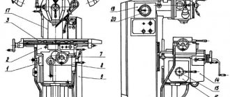
The machine drives are controlled from control panels: main 6 and side 7 (Fig. 1).
The main control panel contains: buttons (keys)
- table drive control;
- spindle control buttons;
- emergency shutdown button.
switches:
- SA3 — operating mode selection;
- SA6 - slow motion of the table.
On the side control panel there are:
- QS3 switch for turning the tool clamp drive on and off;
- SA5 switch for selecting the table movement coordinate;
- SB5 button for pulse switching on the spindle;
- duplicate control buttons for machine drives and emergency shutdown.
On the right side wall of the electrical cabinet there is a handle 3 for the input switch.
On the cover of the left niche of the frame there are switch handles:
- QS1 - reverse of the first spindle;
- SA2 - cooling pump;
- QS2 - reverse of the second spindle;
- SA7 - cycle selection;
- SA4 - selecting the type of frame cycle.
Alarm and interlock devices
For the purposes of convenience, reliability and safety of working on machines, the electrical circuit provides the following light alarms and electrical interlocks:
- a) on the left side wall of the control station there is a warning lamp HL3 with a milky filter, indicating the on state of the input switch, and HL1 with a red filter, warning of a malfunction of the control circuit;
- b) an HL2 signal lamp with a red filter is installed in the control station, warning maintenance personnel about the on state of the input switch when the electrical cabinet door is open
- c) a locking device (SQ11, SA1) is installed in the control station, which ensures blocking of the input switch with the control station door;
- d) the tool clamp control relay K1 blocks the main drive switching circuit (see line 28);
- e) movement of the table in operating mode is excluded when the main movement drive is turned off (see KT4 line 48);
- f) the possibility of turning on the main movement drive when it is braking is excluded (see KT3, line 40);
- g) mutual interlocking eliminates the possibility of turning on the moving parts of the machine in mutually opposite directions;
- i) when the table and main movement drives are simultaneously turned off, the shutdown sequence is ensured (see KT4 line 29);
- j) the possibility of simultaneous activation of the feed, fast and slow speed clutches is excluded;
- k) when moving the table in the transverse and vertical directions from the handles, the possibility of starting the table drive in these directions from the buttons is excluded. See limit switches SQ13, SQ14;
- l) when the tool clamp drive is turned on, the main drive is automatically braked (see QS3.7 line 119);
- m) in the automatic control mode, the controls used in the manual and jog control modes are disabled (see SAZ.3 line 45);
- n) the control station is equipped with terminal clamps 45, 46 for connecting control devices for the workpiece clamping mechanism.