Leash devices
TO
category:
Turning
Leash devices
Next: Cutters for processing external cylindrical surfaces and installing them in the tool holder
Drive devices are used to transmit rotation from the spindle to the workpiece installed at the centers. The simplest of them is a turning clamp. The bent shank of the clamp fits into the radial groove of the faceplate mounted on the machine spindle. Rotating together with the spindle, the faceplate carries with it the clamp, and with it the workpiece installed in the centers. Clamps with straight shanks are also used; to work with them, drive faceplates are used, in which a pin or bar serves as a lead. Working with a clamp poses a certain danger: there may be cases where the shank of the clamp catches a worker’s clothing. Therefore, for safety reasons, faceplates with protective covers are used (safety faceplates). To avoid damaging the surface of the workpiece being clamped, a split sleeve is put on it or rubber is placed under the clamping bolt.
To reduce the time for installing and removing the clamp, quick-release and self-clamping clamps are used. The main part of a self-clamping drive clamp is a ring that is put on a workpiece installed in the centers. When the spindle is turned on, the plang;aiba acts on the driver, which, turning on an axis, grips the workpiece with a corrugated working surface. When cutting, this clamp clamps the workpiece more reliably, the larger the cross-section of the chips.
1. CARBIDE CENTERS: a - with a deposited layer of hard alloy, b - with a soldered tip
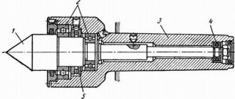
2. ROTATING CENTER FOR LIGHT RADIAL LOADS (UP TO 200 KG): 1 - cover. 2 - radial bearing. 3 - torus bearing. 4 — body with shank. S - center. 6 - needle bearing
3. APPLICATION OF THE CLAMP (a), DESIGNATION DIAGRAM (b): 1 - faceplate, 2 - front center. 3 - clamp. 4 - rear center, 5 - quill
4. SAFE PLATES: a – with a driving pin, b – with a driving strip (plbnka) “3- leash (finger or
5. SELF-CLAMPING DRIVE CHUCK 1—rings, 2—axle. 3—spring. 4 - leash
6. SELF-CLAMPING DRIVE CHUCK: 1 - faceplate, 2 - “floating ring”, 3 - cam, 4 - cam axis
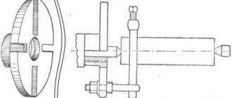
7. DRIVE MANDLE: 1 - mandrel body with a conical shank. 2 - drive washer with end teeth. 3 - floating center. 4—spring. 5 - spring adjusting screw
The transmission of torque from the spindle to the workpiece is often carried out with a special driving self-clamping chuck (faceplate) with eccentric cams. The design of such a chuck by the innovative turner V.K. Seminsky is shown in Fig. 36. The presence of a “floating ring” on which the axes of the cams are located makes it possible to secure workpieces with an uneven outer surface (for example, forgings).
In Fig. 7 shows a driving mandrel, which carries the workpiece with teeth located at the working end of the driving washer. The workpiece is pressed against the teeth by the center of the tailstock.
The driver for rollers of small diameters can be a corrugated driver. To process tubular workpieces, “brushes” are also used, which have teeth on the working surface - corrugations. Small diameter rollers (up to 20 mm) can be fixed in reverse centers. The end cones and chamfers are pre-machined on the workpiece, and the front and rear centers have corresponding holes with seat cones. The workpiece is driven into rotation due to friction between the front return center and the workpiece. The reverse center fastening method is used only for finishing. Installation of workpieces in the centers (with putting on a clamp) lasts 0.25-0.6 minutes (depending on the mass of the part). Installation in centers with a driving self-clamping chuck (faceplate) or mandrel, as well as installation in friction clamps, reduces the time for clamping and removing the part by almost half. Experienced turners process small-diameter rollers, securing them in reverse (with a chamfer base).
8. SECURING THE WORKPIECE WITH THE HELP OF A DRIVE (a), DESIGNATION DIAGRAM (b): 1.2 - centers
Rolled blanks are mounted in a three-jaw chuck with a center support installed in the tailstock quill.
Classification of lathe chucks
There are several types of classifications: according to the number of cams, type of clamp, fixation mechanism, type of execution, accuracy class.
By the number of jaws in the chuck
Cams are responsible for the quality of fastening of parts. They are made of high quality metal.
Double cam
Options secure asymmetrical parts that are not processed. But they are also used for standardized workpieces.
Four-jaw
The 4 jaw chuck consists of four units that function independently. Used for processing rectangular and square options.
By type of workpiece clamp
The chuck jaws are divided into direct and reverse. Virtually no effect on performance. Selected depending on the type of cartridge input.
Reverse
Clamping occurs from the inside, from the inside. The object being processed is chosen to be hollow, so that it can catch on.
According to the workpiece fixation mechanism
The fixation mechanism is an important characteristic that determines the quality of work.
Wedge
Fastening occurs using three cams on a straight platform. Wedge variations are used for digitally controlled equipment.
Collet
There are no standard clamps. Their role is played by bushings with pliers (up to six pieces). Can be used on standard mechanical machines.
Lever
The part is processed by moving the mechanism with a lever. Quite a costly and lengthy process. Used to work with special, complex textured parts.
Drilling
The parts are secured by the pressure of the wrench. The principle of operation is similar to the operation of a drill, only in the opposite direction.
Thermal cartridges
An extraordinary look, which is practically not used in machines made in Russia. For fastening, the hole is heated, and for removal, too.
Hydraulic chucks
The mechanism is the same as the previous one, but not temperature is used, but the hydrosphere. The liquid medium additionally dampens vibrations.
Such options are practical. The design includes clamps that are tightly fixed to the workpiece independently.
GOST 2675-80 SELF-CENTERING THREE-JAW CHUCKS
1. The standard applies to self-centering spiral-rack three-jaw chucks of accuracy classes N, P, V, A, installed on machine spindles through adapter flanges and directly on the flanged ends of the spindles.
2.Cartridges must be made of the following types:
Type 1 - with a cylindrical, centering belt and with fastening through an intermediate flange in accordance with GOST 3889-80.
Type 2 - with fastening directly to the flanged ends of the spindles under a rotary washer in accordance with GOST 12593-72;
Type 3 - with fastening directly to the flanged ends of spindles in accordance with GOST 12595-85.
1, 2. (Changed edition, amendment No. 1).
3. Cartridges of all types are manufactured in the following versions:
- with solid cams,
- with assembled cams.
4. The main dimensions of cartridges of types 1, 2, 3 must correspond to those indicated in drawing 1 and table 1.
An example of a symbol for a type 1 chuck, 200 mm in diameter with solid jaws, accuracy class H:
Cartridge 7100-0007 GOST 2675-80
The same, type 2 chuck with a diameter of 200 mm, mounted on a spindle with nominal size 5, with prefabricated jaws, accuracy class P:
Cartridge 7100-0032-P GOST 2675-80
Three-jaw manual self-centering lathe chucks ∅250-500 mm
Lathe rack-and-pinion three-jaw manual self-centering chucks are designed for installation on universal and special lathes.
The chuck design ensures the transmission of high clamping forces with significantly less torque on the clamping wrench compared to spiral chucks.
Wedge rack chucks have high wear resistance, long service life, and stability in obtaining high accuracy of centering of parts.
The cartridges are made on the basis of a steel body, the grooves for the cams are hardened by high-frequency heat.
The basic package includes a set of hardened reversible cams, which act as direct and reverse cams during reinstallation.
At the customer's request, the chucks are equipped with an additional set of non-hardened jaws and intermediate jaws for installing special settings on them.
Dimensions and technical characteristics of lathe chucks PR
| 1601.B | Lathe chuck 80mm 3 x jaw 3-80.01.11 Beltapaz | set | 11500.00 rub. |
| Description: Lathe chuck 7100-0001 is a component for clamping the material being processed. This cartridge is manufactured with a cylindrical belt and fastened..Weight: 2.5 kgRead more | |||
| 1601 | Lathe chuck 80mm 3 x jaw 7100-0001 | set | 7300.00 rub. |
| Description: Lathe chuck 7100-0001 is a component for clamping the material being processed. This cartridge is manufactured with a cylindrical belt and fastened..Weight: 2.5 kgRead more | |||
| 1602.B | Lathe chuck 100mm 3 x jaw 3-100.02.11 BelTapaz | set | 12565.82 rub. |
| Description: Lathe chuck 7100-0002 is a component for clamping the material being processed. This cartridge is manufactured with a cylindrical belt and fastened..Weight: 4 kgRead more | |||
| 1602 | Lathe chuck 100mm 3 x jaw 7100-0002 | set | 8300.00 rub. |
| Description: Lathe chuck 7100-0002 is a component for clamping the material being processed. This cartridge is manufactured with a cylindrical belt and fastened..Weight: 4 kgRead more | |||
| 1603 | Lathe chuck 125mm 3 x jaw 3-125.03.11 BelTapaz | set | 13900.00 rub. |
| Description: Lathe chuck 7100-0003 is a component for clamping the material being processed. This cartridge is manufactured with a cylindrical belt and fastened..Weight: 6 kgRead more | |||
| 1603 | Lathe chuck 125mm 3 x jaw 7100-0003 | set | 9100.00 rub. |
| Description: Lathe chuck 7100-0003 is a component for clamping the material being processed. This cartridge is manufactured with a cylindrical belt and fastened..Weight: 6 kgRead more | |||
| 1606.B | Lathe chuck 160mm 3 x jaw 3-160.05.11P BelTapaz | set | 16100.00 rub. |
| Description: Lathe chuck 7100-0005 is a component for clamping the material being processed. This cartridge is manufactured with a cylindrical belt and fastened..Weight: 7 kgRead more | |||
| 1606 | Lathe chuck 160mm 3 x jaw 7100-0005 | set | 12400.00 rub. |
| Description: Lathe chuck 7100-0005 is a component for clamping the material being processed. This cartridge is manufactured with a cylindrical belt and fastened..Weight: 7 kgRead more | |||
| 1606.1 | Lathe chuck 160mm 3 x jaw 7100-0005 (straight jaws) BelTapaz | set | 9000.00 rub. |
| Description: Lathe chuck 7100-0005 is a component for clamping the material being processed. This cartridge is manufactured with a cylindrical belt and fastened..Weight: 7 kgRead more | |||
| 1608 | Lathe chuck 160mm 3 x jaw 7100-0027 BelTapaz | set | 23900.00 rub. |
| Description: Lathe chuck 7100-0027 is a component for clamping the material being processed. This chuck is manufactured with fastening to the flanged ends of the spindles. Weight: 12 kgRead more | |||
| 1610 | Lathe chuck 160mm 3 x jaw 7100-0029 BelTapaz | set | 23900.00 rub. |
| Description: The lathe chuck 7100-0029 is a component for clamping the material being processed. This chuck is manufactured with fastening to the flanged ends of the spindles. Weight: 12 kgRead more | |||
| 1612.B | Lathe chuck 200mm 3 x jaw 3-200.04.14V BelTapaz | set | 21300.00 rub. |
| Description: Lathe chuck 7100-0007 is a component for clamping the material being processed. This cartridge is manufactured with a cylindrical belt and fastened..Weight: 17 kgRead more | |||
| 1618.B |
Outer diameter of the chuck D, mm Height of the chuck, mm Diameter of the passage hole d, mm Conventional size of the connecting cone Diameter of the connecting belt D1, mm Working stroke of the cam, mm Maximum torque on the wrench, daN×m Total clamping force in the jaws, daN Maximum permissible frequency rotation, min-1 Chuck mass, kg
| 250 | 315 | 400 | 500 | |
| H1 | 106 | 121 | 138 | 143 |
| H2 | 116 | 131 | 153 | 153 |
| H3 | 116 | 131 | 148 | 148 |
| H4 | 106 | 121 | 138 | 143 |
| 65 | 95 | 120 | 180 | |
| GOST 12593 | J6;J8 | J6;J8;J11 | J8;J11 | J8;J11 |
| GOST 12595 | K6;K8 | K6;K8;K11 | K8;K11 | K8;K11 |
| GOST 26651 | D6;D8 | D6;D8;D11 | D8;D11 | D8;D11 |
| 210 | 270 | 340 | 440 | |
| 8,0 | 10,7 | 12,0 | 16,0 | |
| 18,0 | 20,0 | 22,5 | 25,0 | |
| 9000 | 12000 | 14000 | 16000 | |
| 3000 | 2300 | 1800 | 1300 | |
| "J" | 34,0 | 67,8 | 110,0 | 175,0 |
| "TO" | 36,0 | 70,0 | 115,0 | 175,0 |
| "D" | 35,0 | 69,0 | 112,0 | 180,0 |
| "C" | 34,5 | 67,2 | 110,0 | 175,0 |
Marking of lathe chucks PR
Comparison table for manual turning chucks GOST 2675-80 JSC "BZSP"GOST 2675-80JSC "BZSP"
| 7100-0011 | PR 315.85.S270 (c) | 7100-0044 | PR 400.120.J8 (c) |
| 7100-0012 | PR 315.85.S270 (c) | 7100-0045 | PR 400.120.J11 (c) |
| 7100-0015 | PR 400.100.S340 (c) | 7100-0046 | PR 400.120. J11 (c) |
| 7100-0016 | PR 400.100.S340 (s) | 7100-0047 | PR 500.180.J8 (c) |
| 7100-0017 | PR 500.150.S440 (c) | 7100-0048 | PR 500.180.J8 (c) |
| 7100-0018 | PR 500.150.S440 (s) | 7100-0049 | PR 500.180.J11 (c) |
| 7100-0035 | PR 250.65. J6 (c) | 7100-0050 | PR 500.180.J11 (c) |
| 7100-0036 | PR 250.65.J6 (c) | 7100-0061 | PR 250.65.K6 (c) |
| 7100-0037 | PR 250.65.J8 (c) | 7100-0062 | PR 250.65.K6 (s) |
| 7100-0038 | PR 250.65.J8 (c) | 7100-0063 | PR 315.85.K6 (c) |
| 7100-0039 | PR 315.85. J6 (c) | 7100-0064 | PR 315.85.K6 (s) |
| 7100-0040 | PR 315.85.J6 (c) | 7100-0065 | PR 400.120.K8 (ts) |
| 7100-0041 | PR 315.85.J8 (c) | 7100-0066 | PR 400.120.K8 (s) |
| 7100-0042 | PR 315.85.J8 (c) | 7100-0067 | PR 500.180.K11 (c) |
| 7100-0043 | PR 400. 120.J8 (c) | 7100-0068 | PR 500.180.K11 (s) |
Jaws for three-jaw wedge rack chucks (PR)
ReversibleUnhardenedBasic (intermediate)UpperCartridge modelPR-250.65 PR-315.95 PR-400.120 PR-500.180
| soft | reversible | |
| Made* | ||
| PR-250.65J6/005 | PR-250.65J6/016 | PR-250.65/030 |
| PR-250.65J6/017 | PR-250.65/030.001 | PR-250.65/030.020 |
| PR-315.85/005 | PR-315.85/019 | PR-315.85/030 |
| PR-315.85/018 | PR-315.85/032 | PR-315.85/031 |
| PR-400.105J11/005 | PR-400.105J11/016 | PR-400.105/020 |
| PR-400.105.J11/017 | PR-400.105/022 | PR-400.105/021 |
| PR-400.105J11/005-01 | PR-400.105J11/016 | PR-400.105/020 |
| PR-400.105.J11/017 | PR-400.105/022 | PR-400.105/021 |
| * - supplied upon customer request and for an additional fee |
Source: https://bzsp.ru/products/lathe-chucks/patrony-tokarnye-klinoreechnye-trehkulachkovye-ruchnye-samotsentriruyushhie/
Drive cartridges with a sunken center
Drive chucks with a sunken center are designed for fastening parts on the outer untreated surface with simultaneous centering by the supplied center 1. By applying pressure to the part, the center is insulated and ensures that its end reaches the stop against the base surface of the nut 2.
The center is locked when clamped automatically by cams 5, which impart rotation to the nuts 4 and sliders 5 (relative to the axis of the chuck). Thanks to the inclined grooves, the sliders are imparted translational movement along the axis of the grooves. In this case, the crackers move along the inclined grooves and send the cams all the way to the nut 2.
| D | clamp d | H | |
| max | min | ||
| 170 | 50 | 10 | 70 |
| 220 | 70 | 20 | 90 |
Related Pages
- Diaphragm cartridges and mandrels
- Solid conical mandrels
- Mandrels and plugs for installation and fastening of workpieces on the external machined surface
- Mandrels and plugs for installation and fastening of workpieces on the internal machined surface
- Mandrels and plugs for installation and fastening of workpieces on the internal untreated surface
- Mandrels and chucks for fastening workpieces on a threaded surface
- Rotating centers
- Machine vice
- Machine tables
- Machine stands
- Dividing devices for machine tools
- Conductors and stands for overhead conductors
- Gripping devices for automatic lines
Great Encyclopedia of Oil and Gas
Page 1
Self-centering chucks and mandrels constitute a special group of multi-link mechanisms. [1]
Self-centering chucks are produced in 4 accuracy classes: a) for universal work - normal accuracy N and increased accuracy P; b) for finishing work - high B and especially high A. [2]
Self-centering chucks for drilling machines do not require increased precision in the diameter of the jaws, as well as their exact location relative to the center of the chuck. They are installed on the machine along a clamped reference part and, as a rule, are used only for the first operation of processing the part without tool guides. And table 13 shows the normals of such cartridges. [3]
| Movable steady rest. [4] |
Self-centering chucks are convenient for securing round symmetrical parts. [5]
Self-centering chucks, as a rule, have three jaws (Fig. These chucks are called spiral bevel gear chucks, since the movement of the jaws / occurs using a spiral 2 and a bevel gear. [6]
Self-centering chucks (collet and jaw) are designed for fastening relatively small tools: collet chucks - for tools with a shank diameter from 2 to 15 mm; three-jaw chucks – for drills with a diameter from 0 5 to 15 mm. [7]
Self-centering chucks ensure precise centering of taps, which is especially important when cutting precise threads. There are two main types of self-centering threading chucks: collet chucks and ball chucks. [8]
Self-centering chucks with balls and compensators are used on multi-spindle machines and are not discussed in this book. [9]
Self-centering chuck for drilling machines. [10]
General design and arrangement of a lathe chuck for a metal machine
The following kits are supplied with the cartridge:
- straight cams;
- reverse cams;
- Cam racks are supplied outside the kit.
The most common is the three-jaw chuck, consisting of:
- monolithic or composite body with three radial grooves for cams;
- cams (direct and reverse) are made of high-quality hard, hardened steel of high strength, connected to the end thread of the spiral disk;
- spiral disk, with a large gear on its reverse side. Associated with the bevel gear gear;
- bevel gears, by rotating a key inserted into the square hole of this gear, a rotational movement is imparted to the spiral disk.
The simplicity of technological methods for basing parts has become the reason for the popularity and spread of the three-jaw chuck on machines used in production
Key
A metal rod, at one end of which a hole is drilled perpendicular to its axis with a metal lever installed in it. Exceeding the length of the lever by 35–40% relative to the height of the key is optimal.
At the lower end of the rod there is a tetrahedral tip, commensurate with the hole inside the bevel gear. Serves as a manual drive of the cams by rotating the spiral disk while securing the workpiece in the working area of the machine.
Spring
Installed on the tip of the key. Upon completion of the operation, the load from the efforts of the hand on the key is removed and the spring, straightening, removes the key from the cartridge socket. If the machine operator inadvertently does not remove the key himself, then the spring does it for him.
Sleeve
A hollow cylinder, in the upper part of which grooves are cut for half-ring crackers. Provides fixation of the bevel gear in the working body of the cartridge. The upper part of the bevel gear with a groove for half-ring crackers is installed in the inner diameter of the bushing.
Gear
The bevel (or small) gear is inserted into the small hole in the chuck body. Its upper part is connected to the grooves of the bushing by means of half-ring crackers.
The small gear is constantly meshed with the teeth of the large gear and is designed to transmit rotational motion to the helical disk of the chuck.
Flange
Adapter flange, faceplate. Designed for a strong and precise connection of the chuck with the working end of the machine spindle. For example, a thread is cut on the TV-4 spindle, an adapter flange (faceplate) is installed on it, onto which the lathe chuck is attached.
Spiral disk
Archimedes spiral, snail, planetary. A metal disk with large gear teeth on one side that are permanently meshed with the bevel gear gear.
On the other side of this disk, a spiral profile is cut out, which is in constant contact with the grooves (racks or combs) of the cams. The latter, moving synchronously, work to clamp, center and fix the part in the processing area of the machine.
The part clamped by the cams is removed by rotating the chuck key in reverse.
Reverse cam
Used for clamping large diameter parts. Each cam has two stages for fastening parts for expansion and one prism for compression.
Cam stages are used to eliminate end runout of the part. In addition, machine operators independently create an additional fastening base on the return cams that works to expand.
Frame
Depending on the design and methods of attachment to the spindle, it can be conditionally divided into monolithic (the body is one basic part) and composite, in which the body is divided into two basic parts:
- Monolithic with a cylindrical belt. It is attached to the spindle through an intermediate flange according to special GOST. Made from high-quality steel and less often from cast iron.
- Composite body. The base part is divided into two components:
- the front part or body (sometimes the front semi-body), it contains a spiral disk and slots for the cams;
- the rear part or flange (often the rear half-body), which houses bevel gears.
Top jaws
They are mounted on the cam rails of the lathe chuck. They are made from unhardened steel grades and are called “raw cams”. Designed for fastening large diameter parts.
State standards regulating the design and dimensions of lathe chucks
- GOST 1654 - General purpose lathe chucks. General technical conditions
- GOST 2571 - Drive lathe chucks. (for spindles according to GOST 12593-72 and GOST 12595-85)
- GOST 2675 — Self-centering three-jaw lathe chucks. Main Dimensions
- GOST 14903 — Self-centering two-jaw lathe chucks
- GOST 24351 — Self-centering lathe chucks 3- and 2-jaw wedge and lever-wedge
- GOST 24568 - Magnetic cartridges. Specifications
- GOST 3890 - Four-jaw chucks with independent movement of the jaws
- GOST 16157 — Membrane chucks for grinding holes in gears
State standards regulate the operational and technical parameters according to which lathe chucks for machine tools are selected:
- A number of possible outer diameters of chucks and, accordingly, a range of workpiece sizes: maximum and minimum diameter (outer and inner), depending on the method of fastening - on direct or reverse cams. The maximum permissible weight of the workpiece is taken into account;
- Method of attaching the chuck to the spindle. Connecting dimensions: diameter of the centering belt or centering cone;
- Location and dimensions of mounting holes in the lathe chuck;
- Limits of turning speed of the lathe chuck;
- The diameter of the hole in the chuck body for installing a rod or pipe;
- Lathe chuck accuracy
Jaw chucks for lathes
On lathes, two-, three- and four-jaw chucks with manual and mechanized clamping drives are used. Various shaped castings and forgings are secured in two-jaw self-centering chucks; The jaws of such chucks are usually designed to secure only one part.
Three-jaw self-centering chucks hold round and hexagonal workpieces or large diameter round rods.
In four-jaw self-centering chucks, square-section rods are fixed, and in chucks with individual adjustment of the jaws, parts of rectangular or asymmetrical shape are fixed.
The most widely used is a three-jaw self-centering chuck (figure below). Cams 1, 2 and 3 of the cartridge move simultaneously using disk 4.
On one side of this disk there are grooves (shaped like an Archimedean spiral) in which the lower projections of the cams are located, and on the other there is a cut bevel gear mated to three bevel gears 5.
When you turn one of the wheels 5 with a key, disk 4 (thanks to gearing) also turns and, by means of a spiral, simultaneously and evenly moves all three cams along the grooves of the cartridge body 6.
Depending on the direction of rotation of the disk, the cams move closer to the center of the chuck or move away from it, clamping or releasing the part. The cams are usually made in three stages and are hardened to increase wear resistance. There are cams for securing workpieces on the internal and external surfaces; when fastening on the inner surface, the workpiece must have a hole in which the cams can be placed.
The jaw chucks can be equipped with a motorized drive – traction or built-in. Chucks with traction drive have clamping elements connected by solid or hollow rods to a pneumatic or hydraulic cylinder.
The figure below shows the design of a two-jaw lever chuck with replaceable jaws 14, which are pre-installed on the workpiece (relative to the axis of rotation) by displacing the nuts 12 (fastened to the jaws 14 with screws 13) along the grooves in the slides 11.
The sliders 11 are moved to the center of the cartridge by levers 10, which, when moving the stop 15 (together with the rod 3), rotate around the axis 9 in the housing 8. When turning, the levers 10 rest on the surface 7.
The movement of the sliders 11 (together with the cams 14) from the center of the chuck is carried out by the conical surface of the stop 15 with the reverse movement of the rod 3, connected to the stop by means of a guide sleeve 6 and connecting parts 2, 4 and 5. The chuck is attached to the machine with screws 1.
The cartridge with a built-in drive (figure below) has a built-in pneumatic cylinder 6 with a piston 5 and is attached to the machine by flange 1. The rubber ring 11 softens the impacts of the piston on the flange 4. O-rings 10 and 12 ensure the tightness of the pneumatic drive.
The sliders 7 (with clamping jaws) have projections 9 that fit into the grooves of the piston 5. The angle of inclination of the grooves is 40.5 degrees, which ensures self-braking conditions.
When air is supplied through channels 2 and 3 into the left or right cavity of the cylinder, the sliders 7 move from the center of the cartridge or to its center and, through the cams 8, unclench or clamp the workpiece. production of screw-cutting lathes
A four-jaw chuck with independent movement of the jaws (figure below) consists of a body 1, in which four grooves are made, in each groove a cam 4 is mounted with a screw 3, which is used to independently move the jaws along the grooves in the radial direction.
Screw 3 is held against axial displacement by block 2. When the cams are rotated 180 degrees, the chuck can be used to fasten workpieces on the inner surface.
On the front surface of the chuck there are concentric circular marks (the distance between the marks is 10-15 mm), with the help of which the cams are set at the same distance from the center of the chuck.
Source: https://turner.narod.ru/dir1/posoba2.htm
Is it possible to make the part yourself?
Of course, making a full-fledged faceplate yourself will be extremely difficult, and even in some cases, too expensive, but there are options that you can make yourself without much expense. They won't fit all the pieces, but they can secure the basic pieces.
Preparation of the faceplate
Apply the parameters you need to the beam. Using a compass, mark a diameter slightly larger than the central hole. This is necessary so that when gluing you do not “eat” a few extra millimeters and make the part smaller than necessary.
Coat the parts you are going to glue with hot glue, stepping back a centimeter from the edge. Hold the parts properly so that they finally stick together.
To make it you will need:
- Tools: Lathe, cutters, plumbing kit, earplugs/earphones for shooting, shield, inverter and all its accessories, electrodes (2.5 mm), hot melt glue, machine.
- Details: Nuts, washers, dry birch firewood. Cut the extended nut in half with the machine running.
Next, take the body washer. Make sure the nut doesn't fall through. Place the nut with its ribs in the center of the washer. Weld half of the nut to the washer, welding first one side and then the other.
When the part has cooled, beat the glass crust and place it on the spindle. Drill several holes on the faceplate; they will help secure large objects in the future.
Next, paint the part before it gets rusty. For example, you can coat the bottom of the piece with ocher. Glue newspaper onto the disc and sanding paper on top. At this point your part is ready.
Typically, faceplates are sold in sets and have a relatively low price, but for those for whom buying a whole set may hurt their wallet, there are separate kits that contain 2-3 parts, including the faceplate itself:
- Faceplate 160 mm (lathe) - 2,500 rub.
- Faceplate for a screw-cutting lathe - 10,000 rubles.
- Chuck + faceplate - 14,000 rub.
- Faceplate 126 mm (from the manufacturer Record Power) - 3,400 rub.
- Chuck flange for installation - RUB 2,300.
- Set of clamps -1,700 rub.
- Faceplate for four-jaw chuck -2,700 rub.
Having disassembled such a number of faceplates, we can conclude how useful their use is when working with the machine. Of course, a faceplate, and even more so a professional faceplate, is not a cheap pleasure, but the result and quality justify the money spent.
Of course, if you are a fan of experiments, making a faceplate yourself is not difficult!
Three jaw chucks
The most common chucks are three-jaw chucks. They are installed on all turning equipment: in home workshops, garages, repair shops, small- and large-scale production.
The most common are 3 types of self-centering chucks:
- spiral:
- rack and pinion;
- eccentric with worm gear.
Three-jaw chucks are equipped with a traction (clamping elements are connected to a hydraulic or pneumatic drive) or a built-in drive. Up to thirty percent of auxiliary time is spent on clamping the workpiece during operation, so the devices are mechanized and reduce the time for installing the product. The most widely used in large-scale and mass production are powered jaw chucks with pneumatic drive. The hydraulic drive is rarely used and is used in situations where it is necessary to maintain small dimensions of the structure. The main advantage of mechanized units is speed and constant clamping force on the jaws.
Detailed video on clamping turning units
Spiral cartridges
3-jaw scroll chucks have been around for over 100 years and, due to their simple design and reliability, are still used in new equipment today. They provide a large range of cam travel and have high efficiency; it is possible to clamp eccentric and non-round workpieces. The disadvantages are rapid loss of accuracy and accelerated wear. The loss of initial accuracy occurs as a result of technological features: the volute is only improving and has low hardness, therefore, it quickly wears out - rapid wear of the centering mechanism occurs. Accelerated wear occurs due to chips and dirt getting into the wedge-shaped gaps between the teeth of the cams.
Used in single and small-scale production. Equipped with direct and reverse cams.
Rack chucks
3-jaw rack chucks get their name because of the principle of operation: a gear rim moves the racks, which simultaneously moves the jaws. More durable than spiral ones, because It is possible to harden and grind the teeth. The body is made of cast or forged steel, the remaining moving parts are alloyed, followed by hardening. They are universal and are used in single or small-scale production.
Advantages:
- stronger clamp;
- greater accuracy;
Flaws:
- Efficiency is lower than that of spiral ones;
- Possibility of clamping from only one position;
- complex design.
Eccentric chucks
3-jaw eccentric chucks are used in large-scale production. All parts of the unit are made of wear-resistant steels, and then undergo hardening and grinding. They have high precision and clamping force. They can be re-adjusted to clamp another part relatively simply - by rearranging the mounted cams.
Lathe chuck: purpose, types and features of choice
Return to article list
It is difficult to imagine the rapid development of the metalworking complex without the constant improvement of machine tools. It determines the speed of sharpening parts, compliance with their geometry, and the quality of surface treatment.
To securely hold the workpiece, a lathe chuck is used to ensure the necessary clamping force and centering accuracy. This article addresses the main issues regarding the selection of devices:
This article will cover the following issues:
Lathe chucks are installed on universal and special machines and are used to fasten parts to the spindle axis. Thanks to their use, reliable fixation is achieved and the clamping force is increased with high torque. The part does not break off, maintains the correct position during operation, reducing the risk of cutter breakage and ensuring high speed of product production.
Chucks for lathes are made from hardened steel, less often cast iron, and differ from each other in design and purpose. In Russia, eight standards have been developed and approved that describe the requirements for these elements. For example, according to GOST 1654-86, there are 4 accuracy classes: A (extra high), B (high), P (increased) and N (normal).
All used lathe chucks are conventionally divided into two groups: jaw and collet. The first ones consist of several movable segments (cams), due to which the part is fixed.
They are used for most operations and differ from each other in design features and purpose.
Collet chucks are available with a retractable, fixed or retractable collet that secures the part in the desired position.
The lathe chuck is also classified according to:
- number of cams (from two to six);
- features of fastening (on the external or internal surface);
- specifics of execution (solid, prefabricated or overhead cams);
- the drive used (manual or mechanical).
Each type of device has its own advantages, features of use and is designed for certain functions.
The 2-jaw chuck for a lathe is used for fastening complex shaped parts, non-cylindrical and asymmetrical workpieces. Their peculiarity lies in the ability to fix untreated surfaces in sponges, providing sufficient adhesion.
All parts of the product are made of steel; moving parts are subjected to heat treatment, which increases their strength characteristics and wear resistance. The dimensions are standardized: diameter varies from 125 to 400 mm. The disadvantages of devices of this type include a high risk of misalignment due to the wide gap between the guides.
The most common type found in industrial production, home workshops, garages and assembly shops. Typically equipped with a traction drive, which reduces the time required for fixation by 30-80%.
Reducing time costs allows you to speed up the process, which is especially important when there is a large load, for example, on serial machines.
The mechanized drive provides another important advantage: the constancy of the clamping force, due to which the part does not warp or fly out at any speed.
a - three-jaw chuck; b - four-jaw chuck.
The 3-jaw chuck for lathe can be either spiral or rack. Spiral structures were one of the first to appear and have been used for more than 100 years due to their simplicity and reliability.
Their advantages include a wide range of clamp travel, the ability to clamp non-round parts and good efficiency. Among the disadvantages: rapid wear, which results in loss of accuracy of the centering mechanism.
Rapid failure is caused by the use of a fragile volute, dirt and metal shavings getting into the gaps.
Drive chuck
Double-jaw drive chucks are normalized (MH 4051 – 62); they can have a floating (spring-loaded) center.
A rapidly rotating drive chuck with a clamp can in some cases cause injury.
| Protective cover used when working with a driving chuck. |
A rapidly rotating drive chuck with a clamp is a source of increased danger and can cause injury.
The pneumatic lever driving chuck is used to secure and rotate workpieces mounted on centers.
The pneumatic lever driving chuck is used to secure and rotate workpieces mounted on centers.
A conventional universal drive chuck is shown in Fig. Under the influence of cutting forces, the workpiece rotates in a clockwise direction and the cams firmly jam the part. As the torque increases, the jamming, and therefore the clamping force, increases.
| Double jaw driver chuck with eccentric replaceable jaws, automatic action.| Chucks with two-jaw drive and sunken centers (dimensions in mm. |
Such leash cartridges, depending on their diameter, can accommodate loads with a total weight of 3 to 6 kg. Then, for example, with m – 3 kg, g 45 mm, n – 500, 1000, 2000 rpm, the centrifugal force pressing the cams to the workpiece will respectively be Rc 34, 138, 552 kgf.
Re-adjustable driving chuck designed by the Odessa Precision Machine Tools Plant. The changeover of the chuck is carried out by moving the strips 2 relative to the bushings 3 towards the center or away from the center of the chuck. The position of the strips is fixed with washers 7 and screws.
The adjustable pin driver chuck designed by NIIPTMASH (Kramatorsk) is intended for installation of workpieces such as shafts with diameters of 80 – 240 mm. The pointed pins can be reinstalled in the housing 8 along different circles depending on the diameter of the workpieces. Replaceable covers 10, fixed to the body 8, have corresponding oval holes that fit into the flats of the pins 9 to prevent them from turning. The pins 9 rest with their spherical ends on the spherical heel 6 mounted on the thrust bearing 5, which ensures self-alignment of the pins along the end of the workpiece. The extension of the floating center 11 and the adjustment of the spring force are carried out by rotating the glass 3 using the flats provided for this purpose. When installing the workpiece in the centers, the rotating center of the tailstock presses the workpiece in the axial direction and the pins cut into the end of the workpiece to the same depth, regardless of the non-perpendicularity of the end of the workpiece relative to its axis.
| Machining parts on rigid and floating front centers. |
The use of a drive chuck with a clamp is associated with a number of disadvantages.
The use of drive chucks eliminates the need to use clamps, which saves time on installing and securing the part and eliminates the possibility of vibration of the part during processing. In type A cartridges, cheeks 3 are mounted on plate 2, set to the size of the square end of the center mandrel. In type B chucks, driving cams 4 are installed to clamp raw parts.
The use of a driving chuck instead of a conventional clamp creates the opportunity to increase the rigidity of the installation of the shafts being turned. The workpiece, wedged between two eccentric cams, is, as it were, one whole with the moving part of the chuck. However, the presence of guaranteed gaps in the chuck mates (not selected when securing the workpiece) significantly reduces the rigidity of the entire system as a whole. Due to these gaps, the resemblance to a hinged support is maintained, since it remains possible to rotate the workpiece at a small angle.
Centers
Based on the size and shape of the workpieces, various types of centers are used when processing them (Fig. 1). The working angle forming the top of the center - a) is always 60°. The conical planes of the tail 2 and working 1 components of the center must be smooth, without nicks. Any roughness creates errors when processing parts.
Fig.1. Centers:
a – straight; b – with a reverse cone; c – with a cut cone; g – spherical; d – with a corrugated working surface; e – with a carbide working surface; 1 – working part; 2 — tail part; 3 – supporting part
The cross-section of the support 3 is always smaller than the small cross-section of the cone of the tail component 2. This feature allows you to dismantle the center by knocking it out of the socket without damaging the conical plane of the tail component. Figure b) shows the center that is used when processing parts with a cross section of up to 4 mm. Instead of centering holes, they have an outer cone with an apex angle of 60°.
It extends inside the center cone, which is why it is called inverse. If it is necessary to trim the end of a part, use the center cut from the back, position - c). It is located in the tailstock quill of the machine.
A center having a working component with a spherical surface - d) is used when processing a part that is not coaxial with the rotation of the machine spindle.
The center, which has a corrugated plane of the working component - d), is used for processing the driverless chuck of parts that have large center holes. At the time of operation, the front center rotates following the workpiece, representing only a support.
The rear center remains stationary and is therefore subject to heavy wear. This is a consequence of loss of hardness as a result of increased heating.
To prevent wear, the working component of the rear center is made of hard alloys - e). When processing workpieces at high cutting speeds, under high loads, rear rotation centers are used (Fig. 2).
Rice. 2. Rotating center:
1 – center; 2 – roller bearing; 3, 5 – ball bearings; 4 – body
An axis is installed in the tail component 4 of this center in the rolling bearings 2, 3, 5. At its end there is a working component 1. This gives it rotation along with the workpiece.
What other GOSTs are associated with lathe chucks?
For various turning parts for metalworking machines, their own standards have been developed that fix all the necessary parameters. Main GOSTs:
- GOST 24351-80 For self-centering three- and two-jaw wedge and lever-wedge elements.
- Standard 3890-82 For four-jaw parts with independent movement of the jaws" indicating the main and connecting dimensions.
- 14903-69 For self-centering two-jaw elements.
- Gosstandart 2848-75 Tool cones. Tolerances. Methods and means of control.
- Gosstandart 12595 – 2003 – metal-cutting machines.
- State Standard 3889 – Flanges for self-centering chucks.
- Standard 12593-72 – spindle flange dimensions
All this technical documentation allows us to summarize and classify the varieties of these basic elements of turning equipment.
Three-jaw options with a diameter of 250 mm are most often used in lathes, both at the industrial and domestic levels. Therefore, the standards for their production in all respects must be strictly observed.
The document regulating self-centering spiral rack elements contains detailed dimensions, as well as separate diagrams and drawings of this part, from which it is possible to determine compliance with the declared data. At the slightest violation of the parameters specified in GOST, the quality of the working process of the lathe is significantly reduced.
Intermediate flanges for self-centering cartridges GOST 3889-80
This standard applies to intermediate flanges intended for installation on the ends of spindles of metal-cutting machines with self-centering general purpose chucks.
Intermediate flanges (they are also called plan washers) are necessary for centering and fastening chucks with a centering belt (GOST 2675 type 1) on any of the 4 types of lathe spindle ends.
GOST 3889-80 (DIN 6350) Flanges must be manufactured in the following versions:
- Version 1 – installed on the threaded ends of spindles in accordance with GOST 16868;
- Version 2 – installed on the flanged ends of spindles in accordance with GOST 12593 under a rotary washer;
- Version 3 – installed on the flanged ends of spindles in accordance with GOST 12595 version 1;
- Version 4 – installed on the flanged ends of spindles in accordance with GOST 12595 version 3.
GOST 3889 Version 1. Intermediate flanges for threaded ends of spindles
GOST 3889 Intermediate flanges for threaded ends of spindles
GOST 3889 Intermediate flanges for threaded ends of spindles
In order to secure a lathe chuck at the front end of the spindle, it is necessary to make or purchase an intermediate (adapter) flange, which is also called a faceplate.
From the spindle side, the intermediate flange must be screwed onto the spindle thread d and very accurately slide onto the centering belt - a cylinder with a diameter of Ø d1 and a length of l mm.
On the side of the lathe chuck, the intermediate flange must have a centering belt - step D4 for precise installation and centering of the lathe chuck on the intermediate flange, and also have through holes for attaching the chuck. Obviously, for each standard size of lathe chuck there must be its own intermediate flange.
It is allowed to install 1 locking device against self-unscrewing on the intermediate flange of the design.
The lathe chuck installation process consists of the following steps:
- The intermediate flange is screwed onto the spindle thread until it stops. The hole in the flange should fit tightly onto the spindle collar
- The screws of the locking device are tightened against self-unscrewing
- Check the runout of the centering belt on the flange (D1) and the supporting end surface on the chuck side
- A cartridge is installed on the centering belt (D1) and secured with bolts
- The radial and axial runout of the chuck is checked
Example: intermediate flange for a TV-4 lathe
Intermediate flange for TV-4 lathe
An example of a designation for a flange of version 1, with a diameter of 100 mm:
Flange 7081-0592 GOST 3889-80
An example of a designation for a flange of version 1, with a diameter of 125 mm:
Flange 7081-0593 GOST 3889-80
Intermediate flange for a lathe with a threaded spindle end
Intermediate flange for a lathe with a threaded spindle end
GOST 3889-80 Intermediate flanges for rotary washer
GOST 3889-80 Intermediate flanges for rotary washer
GOST 3889-80 Intermediate flanges to the ends of spindles type A. Version 1
GOST 3889-80 Intermediate flanges to the ends of spindles type A. Version 1
CHAPTER 7. ACCESSORIES FOR TURNING AND
CIRCULAR GRINDING MACHINES
Centers for turning and cylindrical grinding machines: - fixed normal GOST 2573-79; — fixed special GOST 2573-79; — rotating normal GOST 8742-75; — rotating special; — floating special; — corrugated special GOST 2575-79, GOST 2576-79.
Rice. 67. Rotating centers for center parts .
Rice. 68. Rotating centers for hollow parts.
Dimensions of centers for center and hollow parts, mm
| Morse cone | Series | d | D | L | l | D 1 | l 1 |
| No more | No less | ||||||
| 2 3 4 5 | Normal | 22 25 28 32 | 5 63 71 80 | 160 180 210 240 | 90 94 101 104 | 56 63 71 80 | 24 26 30 34 |
| 4 5 | Reinforced | 36 40 | 75 90 125 | 210 250 340 | 111 114 150 | 75 90 125 | 36 45 56 |
Rice. 69. Floating center for CNC machines.
Rice. 70. Grooved leader center.
Rice. 71. Center with a driving device.
Rice. 72. Cut center for processing the end surfaces of parts.
Rice. 73. Drive chuck with two eccentric cams (1 - weight; 2 - cam; 3, 4 - springs; 5 - pusher; 6 - spacer sleeve; 7 - screw; 8 - flange; 9 - drive pin; 10 - chuck body) .
Rice. 74. Scheme of turning a workpiece using the longitudinal feed method using a drive chuck and a clamp. Turning using the longitudinal feed method is carried out using a clamp 1, which is attached to the workpiece, and a drive chuck 3, mounted on the spindle of the lathe. Workpiece 2 is installed in the centers.
Rice. 75. Scheme for determining the force of pressing the workpiece from the tailstock side of the machine. Q
— the force of pressing the workpiece from the tailstock side;
Px,
and
Ru
- cutting resistance forces;
D
—diameter of the workpiece;
L
is the length of the workpiece;
l
— tailstock center overhang;
a
is the center angle;
b
is the angle between the center and the vertical
.
Rice. 76. Three-jaw driving chuck (1 - cam; 2 - pin; 3, 12 - axles; 4 - chuck body; 5 - threaded plug; 6 - spring; 7 - conical part of the body; 8 - floating center; 9 - screw; 10 - weight; 11 - casing; 13 - cover; 14 - spring).
RIGID CENTER MELLS
Rice. 77. Smooth conical mandrel (1 - mandrel; 2 - workpiece).
Rice. 78. Smooth mandrel with key.
Rice. 79. Cylindrical mandrel for pressing .
Mrez - moment of cutting forces; Рх — cutting resistance force; Mtr is the moment of friction on the contact surface; d—diameter of the mandrel; D—diameter of the workpiece being processed; l is the length of the workpiece being processed.
Rice. 80. Conical mandrel (1 - mandrel; 2 - workpiece).
Rice. 81 Smooth center mandrel (1 - mandrel; 2 - flange; 3 - workpiece; 4 - nut; 5 - washer).
Rice. 82. Cam spindle mandrel. Q
— axial force on traction;
D
— landing diameter;
d
is the diameter of the cams;
d1
– rod diameter;
l
is the length of the mandrel.
Rice. 83. Thin-walled mandrel with hydroplastic (1 - lever; 2 - plunger; 3 - hydroplastic; 4 - workpiece; 5 - expansion bar; 6 - rod). Q
— force on the cylinder rod.
Rice. 84. Cantilever mandrel with disc springs (1 - package of disc springs; 2 - blank). R
— radius of the workpiece surface being machined;
Q
is the axial force on the rod of the mechanized drive.
Rice. 85. Thin-walled bushing for fastening workpieces. D
— diameter of the bushing mounting surface;
h
is the thickness of the thin-walled part of the bushing;
T
is the length of the support belts;
t
is the thickness of the support belts;
Smax
is the maximum gap between the bushing and the workpiece;
lk
is the length of the contact section of the bushing;
lз
is the length of the workpiece;
Dз
– diameter of the base surface of the workpiece;
d
is the diameter of the hole in the bushing support bands.
Rice. 86. Universal two-jaw chuck.
a - general view of the cartridge; b - diagram of the cartridge mechanism. W
— clamping force;
Mcr
- required torque on the key;
L
—handle length;
D
—diameter of the clamped part;
l1
is the length of the cam guide;
l2
is the distance between the axis of the clamping screw and the axis of the prism;
a1
is the cam prism angle.
Rice. 87. Three-jaw self-centering chuck
(1 - body; 2 - disk; 3 - rack; 4 - screw; 5 - overhead cam; 6 - bevel gear; 7 - cover). N
— width of the cartridge;
D
is the diameter of the cartridge body.
Rice. 88. Diagram of a wedge-plunger lathe chuck (1 - body; 2 - plunger; 3 - wedge; 4 - ball). Q
— clamping force with one plunger;
W
—drive traction force;
a
is the angle of inclination of the wedge cone;
a
is the thickness of the housing liner
.
Rice. 89. Universal three-jaw chuck with a power drive (1 - body; 2 - cam; 3 - block; 4 - screw; 5 - replaceable cam; 6, 7 - bushings; 8 - rod; a - groove in bushing 6; b - protrusion cam 2). Q
— axial force on the rod of the mechanized drive;
W
- chuck cam clamp.
Rice. 90. Universal four-jaw chuck (1 - rod; 2, 3, 4, 7 - bushings; 5 - lever axis; 6, 10 - levers; 8 - floating ball; 9 - cam; 11 - lever axis). Used for installation and clamping of non-circular parts .
Rice. 91. Cartridge with a permanent magnet (1 - key; 2 - screw; 3 - bushing; 4 - nut; 5, 7, 12 - plates; 6 - permanent magnet; 8 - cartridge body; 9, 10 - inserts; 11 - upper plate; 13 - plug; 14 - plate; 15 - intermediate plate; 16, 17 - stops).
Rice. 92. Four-jaw chuck with independent movement of the jaws .
There are two types of chucks: Type A - for mounting on the flange end of the spindle;
Type B - for mounting on the threaded end of the spindle. The figure shows a chuck for mounting on the flange end of the spindle: Version 1
- with mounting on the flange end of the spindle;
Version 2
- with mounting on the flange end of the spindle under the washer.
Rice. 93. Magnetic chuck PTM-250 (1 — adapter plate; 2 — moving block; 4 — conical wheel; 5 — housing; 6 — driven wheel).
Rice. 94. Self-centering lever-wedge two-jaw chuck.
Chuck dimensions, mm
| D | D 1 | D 2 | L | B | d | d 1 | d 2 | d 3 | n | Cam stroke |
| M12 | M08 | M08 | ||||||||
| M12 | M08 | M10 | ||||||||
| M20 | M10 | M12 | ||||||||
| M20 | M12 | M12 | ||||||||
| M20 | M12 | M16 | ||||||||
| M24 | M16 | M20 |
Rice. 95. Clamping device for processing a bevel wheel-disc
(1 - retainer; 2 - outer disc-shaped membrane; 3 - rod; 4 - inner disc-shaped membrane; 5 - machined wheel; 6 - support wheel; 7 - mandrel; 8 - key; 9 - disc spring; 10 - bushing) .
When fixing the bevel wheel-disc, the rod 3
the clamping force
P.
Rice. 96. Round electromagnetic chuck for a lathe for fastening thin flat parts (1 - metal casing; 2 - textolite shield; 3 - labyrinth ring; 4 - body; 5 - nut; 6 - coil; 7 - fixed nut; 8 - slip rings ; 9 — clamp; 10 — pin; 11 — brush holders with brushes).
Rice. 97. Devices for fastening gears during their processing:
a - for processing bevel gears (1 - spindle; 2 - stop); b - with rigid centering (1 - washer; 2 - key; 3 - gear; 4 - flange; 5 - rod); c — clamping device for a wheel with a hub (1 — gear; 2 — rod; 3 — collet; 4 — screw); g — clamping device for fastening the differential satellite (1 — template; 2 — differential satellite; 3 — collet; 4 — rod).
Rice. 98. Diaphragm cartridge (1 - membrane; 2 - rod; 3 - gear; 4 - separator; 5 - roller; 6 - cam; 7 - pin; 8 - bar). a - roller arrangement diagram; b - diagram of a cartridge with three wedge fingers.
Rice. 99. Membrane chuck for installing and clamping cylindrical gears (1 - chuck body; 2, 5, 8 - screws; 3, 4, 7 - bushings; 6 - ball; 9 - faceplate; 10 - membrane (disk); 11 - spherical support; 12 — spherical washer; 13 — replaceable cam; 14 — rubber rod; 15 — roller; 16 — ring; 17 — sector; 18 — block). The diaphragm chuck has five jaws to ensure high centering accuracy when grinding gear teeth.
Rice. 100. Diaphragm cartridge
(1 - membrane cartridge body; 2 - rod; 3 - membrane; 4 - cartridge cam; 5 - workpiece): a - the part is clamped in the membrane cartridge; b - cartridge in an uncompressed state. W
— radial force on one cam of the membrane cartridge;
Q
- force on the shield;
d
is the diameter of the part;
d
- distance from the membrane to the middle of the cam.
Rice. 101. Cartridge with ring diaphragms:
a - annular membrane; b - diagram of the mechanism of the cartridge with annular membranes 1 - body; 2 - workpiece; 3 - bushing; 4 — membrane package; 5 - rod). W
- traction force;
Q
is the force acting on the workpiece;
b = 9…12° -
angle of inclination of the membrane in a deformed state;
D1
is the outer diameter of the membrane;
d1
is the diameter of the hole in the membrane;
t
is the thickness of the membrane.
Rice. 102. Collet chucks:
a - with a retractable collet; b - with a retractable collet. Used for clamping calibrated rods of different profiles processed on turret machines and automatic rod machines. N
— axial force;
Q
is the radial force acting on the part;
Q1
is the pre-compression force of the collet blades;
a = 30...40° - angle at the apex of the collet cone; j = 6...8° - friction angle; l
is the length of the collet blade from the point where it touches to the middle of the collet cone;
D
is the outer diameter of the collet blades;
s
is the thickness of the bending blade of the collet.
Classification of lathe chucks
There are several types of classifications: according to the number of cams, type of clamp, fixation mechanism, type of execution, accuracy class.
By the number of jaws in the chuck
Cams are responsible for the quality of fastening of parts. They are made of high quality metal.
Double cam
Options secure asymmetrical parts that are not processed. But they are also used for standardized workpieces.
Four-jaw
The 4 jaw chuck consists of four units that function independently. Used for processing rectangular and square options.
By type of workpiece clamp
The chuck jaws are divided into direct and reverse. Virtually no effect on performance. Selected depending on the type of cartridge input.
The clamping occurs externally. The cams are located on top and grab the part.
Reverse
Clamping occurs from the inside, from the inside. The object being processed is chosen to be hollow, so that it can catch on.
According to the workpiece fixation mechanism
The fixation mechanism is an important characteristic that determines the quality of work.
Wedge
Fastening occurs using three cams on a straight platform. Wedge variations are used for digitally controlled equipment.
Collet
There are no standard clamps. Their role is played by bushings with pliers (up to six pieces). Can be used on standard mechanical machines.
Lever
The part is processed by moving the mechanism with a lever. Quite a costly and lengthy process. Used to work with special, complex textured parts.
Drilling
The parts are secured by the pressure of the wrench. The principle of operation is similar to the operation of a drill, only in the opposite direction.
Thermal cartridges
An extraordinary look, which is practically not used in machines made in Russia. For fastening, the hole is heated, and for removal, too.
Hydraulic chucks
The mechanism is the same as the previous one, but not temperature is used, but the hydrosphere. The liquid medium additionally dampens vibrations.
Self-clamping
Such options are practical. The design includes clamps that are tightly fixed to the workpiece independently.