Spread the love
Here is an explanation of the G33/G32 CNC G code that you will see on almost every CNC machine. The Fanuc CNC system only implements the G32 G code for special threading, and no G33, but regardless of whether it is G33 or G32, the functionality is the same. All the functions we can do with G33 on most CNC controls, we can do with Fanuc G32 G Code. Below I'll sometimes just use G33, but this all applies to G32 as well.
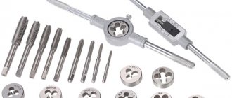
Stages of thread cutting with a machine-hand tap
- The first step is marking in accordance with the drawings.
- According to the marks, punching is carried out with a sharply sharpened core.
- Drill with medium pressure at low speeds. The drill should be at right angles to the surface. Before starting work, the drill is lubricated. If the hole depth is large, then lubrication is carried out not only before starting, but also during operation. The depth of the blind hole should be slightly greater than the length being cut. If there is no reserve, the thread may be incomplete.
- The quality of the result can be improved by countersink processing, which reduces the taper and ensures parallelism of the side surfaces.
- The tap is secured in the driver, its tip is lubricated and inserted into the hole strictly at right angles to the surface. Make the first turn, lightly pressing the knob from above. After the first turn forward, make a half turn back to remove chips. Particular care is taken when using a multi-tool - it is fragile and easy to damage. It's easier to work with complete models.
Marking
The marking of taps begins with a letter indicating the type of thread. M for metric; G for pipe; Tr for trapezoidal. Taps for inch threads are marked without a letter.
Features of marking a tap for threading
Next comes the diameter in millimeters for metric and in inches with whole fractions for inch
I cut tapered threads in two ways.
If the thread has a non-standard pitch, the next step is the designation of the pitch in millimeters or in turns per inch.
If the tap is made of hardened stainless steel, HSS (Hardened Stainless Steel) is added to the marking
For left-hand thread taps, LH (Left Hand) is added at the end of the marking.
Markings and accuracy classes
In accordance with GOST 6111-52, inch tapered threads are divided into 3 accuracy classes, designated by numbers from 1 to 3. After the digital values, a letter is placed indicating the type of cutting (A - external, B - internal). Class 1 includes threads with a low degree of cutting accuracy. Representatives of category 2 are threads of medium precision. Class 3 includes high-precision options, performed according to strict standards.
To determine the quality of a product, it is necessary to study its nomenclature with designations. The type of cutting is indicated by a separate letter. For example, the symbol R denotes an inch tapered thread. This is followed by the diameter value, expressed either as a whole number or as a fraction. The symbols L (Left) and R (Right) indicate the direction of the turns. At the end of the marking the make-up length is written. In some notations the class is also written.
To correctly label a product, you need to study its qualities. Gauge gauges that determine many characteristics of inch threads are ideal for measurements. But in most cases these numbers are tabular values. In rare cases, people resort to using rulers. It is worth considering the unit of measurement of the thread in order to correctly determine the designation.
Current standards
The design and parameters of taps for thread cutting are described in GOST 3266-81: “Machine and hand taps. Design and dimensions."
- Machine taps for metric threads - GOST 8859-74.
- Nut taps for metric threads - GOST 1604-71
- Nut taps with a curved shank for metric threads - GOST 6951-71.
Foreign standards DIN 352, ISO 529 and others do not contradict GOST, with the exception of the tail section being shorter by 1 cm
If you find an error, please select a piece of text and press CtrlEnter.
A tap is a tool that can be used to quickly and accurately cut a thread in a prepared hole. This is a rod divided into a working part and a shank. The shank is used for fixation in the driver or chuck of the machine. Chip removal is provided by longitudinal or helical grooves located on the cutting part. For the manufacture of this tool, carbon or high-speed steels are used. To cut internal threads efficiently, you need to know how to choose the right tap and prepare the hole.
G32 Screw cutting mode
G00 X8.0 Z5.0;
X4.9; G32 Z-15.0 F0.8; G00 X8.0; Z5.0 X6.0; X4.8; G32 Z-15.0 F0.8; G00 X8.0; Z5.0 X6.0; X4.75; G32 Z-15.0 F0.8; Before we look at taper threading, let's look at how the G32 works with a standard threading sequence. Here is part of the program using this command.
Feel free to download the infographic on this page for reference.
Let's look at each block to see what's happening.
G00 X8.0 Z5.0; Faster transition to a safe starting position, provided that the reference point is on the front surface of the part.
X4.9; Still in fast mode with G00 active, we go down to the first cut depth, taking a depth of 0.1mm.
G32 Z-15.0 F0.8; This is where we tell the machine to lock the spindle from rotating at feed speed so that we can cut the thread in the same place every time. From now on, every time we call G32, the machine will cut the thread along the same path as the previous one. The Z distance is the end of the thread and F is the pitch. We cut M5 threads at 0.8mm pitches.
G00 X8.0; After the first pass we program the tapping points. Increasing to X8.0mm gives us some clearance when we go back to the start of the thread.
Z5.0 X6.0; If desired, we can move along multiple axes to speed up the process. Moving 5mm to the right of the front edge will allow us to engage the threads to remove any play that may be present.
4.8; We are now ready to make the next 0.1mm deep pass. We can control the depth of each pass and reduce it as we approach the final depth.
G32 Z-15.0 F0.8; G32 will lock our turret and spindle in the same place as before, so the next thread pass will go on top of the last one. We then simply repeat this going down the X until we reach the final thread depth.
Types of instruments
The appropriate tool is selected depending on the characteristics of the material being processed, the required productivity and other parameters. Using different types of taps, you can cut metric or inch internal threads with a cylindrical or conical profile.
According to the method of conducting the process, models are distinguished:
- Pass-through (universal). Their working part consists of three zones. The first performs rough cutting, the second – intermediate, and the third – finishing.
- Complete. To perform a full range of work, several tools are used - for roughing, intermediate and finishing cutting. The sets consist of three taps, less often of two (for roughing and finishing). For processing particularly strong metals, kits with 5 tools are used.
The tool is made of two types: for processing holes manually or using metal-cutting equipment.
- Machine-manual. Has a square shank. Works complete with a holder with two handles - a knob.
- Machine. Installed in the chuck of metalworking machines of various types.
READ Is it possible to cut threads on spokes?
Taps of different designs are used for cutting threads in blind and through holes:
- For non-passable holes, use a complete tool without a conical tip. The work is usually done with a crank.
- In through holes, threads are made using taps with a conical tip. Most often these are varieties of universal type tools.
The channels for removing chips have different shapes: straight, screw, shortened.
Manual taper thread cutting.
Chip channels of any shape are suitable for processing materials of low hardness. To tap threads in high-hardness materials, such as stainless and heat-resistant steels, use only a tool in which the cutting segments are staggered.
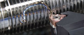
Thread cutting on a lathe: technology
Forming threads on metal workpieces in the form of bodies of rotation is one of the most popular and at the same time complex turning operations. The difficulty lies in both making basic equipment settings and preparing auxiliary tools. In order for thread cutting on a lathe to comply with the technical specifications, you must adhere to the technology for its implementation and do not forget about safety rules.
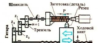
Preparing the machine
Regardless of the type of lathe and working tool, carving will be done by machining.
Through the machine settings, the operator determines the angle of the helical line of influence on the surface of the workpiece, which will have a perpendicular position relative to the axis of rotation.
Here it should be noted that the machines have different power and, accordingly, spindle speeds - in order for the cutting tool to efficiently cope with its task, it is important to initially correctly correlate the angle of influence and the speed of the engine.
An important parameter is the step between the cutting lines - it is also taken into account in the equipment settings and appropriate adjustments are made in terms of the position of the tool relative to the workpiece.
Since thread cutting on a screw-cutting lathe is usually carried out in several approaches, it is advisable to save the primary parameters until the operation is completed.
Even if the step along the threading line is maintained, there remains a risk of violating the positions of the beginning and end of the deformation sections, which may not coincide with each other. It is important to keep these nuances in mind before starting work.
Types of thread
Turners distinguish between even and odd threads. In the first case, we are talking about cuts, which ultimately form an even number of cutting lines in steps. Accordingly, odd cutting leaves odd threads. From the point of view of the operation, even cutting threads on a lathe will have its advantages.
For example, after each approach, the operator can launch a sliding nut in the support and quickly return it back with the cutter manually, without stopping the operation of the equipment.
Then, with each new pass of the sliding nut, the tool will automatically be directed to the original cavity, which ensures a certain accuracy of the operation.
In turn, odd cutting requires, after each pass, the support to return to its original position along with the cutter, which cannot be done without starting the reverse stroke.
Multi-pass and vortex cutting can be placed into separate categories. So, in the first case, cutting multi-start threads on a lathe will require precise angular separation of the workpiece during transitions from one groove to another. The initial calculation of the pitch and cutting line parameters is important here. As for the whirlwind thread, it requires additional installation of a rotating cutting head on the support carriage. Several individual cutters can be fixed on it, each of which will cover its own area of work.
Inch and metric cutting
Inch cuts are used for metal pipes. Typically, such threads are obtained from fittings, which are subsequently used to assemble a metal or plastic pipeline. The standards for creating such cutting are determined by GOST 6357-81. Based on the technical document, we can conclude that the main parameters of inch cutting are pitch and diameter. Moreover, the second characteristic is estimated as the distance between the extreme points of the thread ridges.
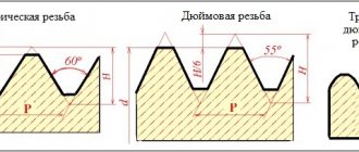
Typical cutting of inch threads on a lathe is carried out by cutters and taps with modifications of the technology as applied to internal processing. Metric cutting is performed taking into account the same parameters, but the shape of the thread flange profile is added to them. In the case of inch cuts, it is most often sharp - in the shape of a triangle. In addition, as the name suggests, classic pipe cutting is calculated in inches, while metric pipe cutting is calculated in millimeters.
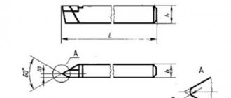
Forming threads with cutters
A cutter is a tool that directly performs cutting. It is made of carbide steel and before work receives a special sharpening in a shape that meets the requirements of the task. It can be used for threading bolts, nuts, studs and other workpieces. The cutter is installed in a machine chuck or multiple head. The work process is divided into several passes - upon completion of each of them, the tool is moved to the side.
Correction of thread formation parameters in this case is carried out by adjusting the caliper, which sets the required depth. At the same time, there are standardized settings. In particular, cutting threads on a lathe with a cutter in increments of up to 0.2 cm will imply that the feed in the transverse movement of the caliper screw will average 0.1 mm per pass.
Simultaneous work with two cutters is also allowed. But here it is necessary to take into account a nuance that can affect the quality of the thread line - the chips released by the leading cutter will cling to the waste of the second tool, which will have, although insignificant, still an impact on the parameters of the edge being formed.
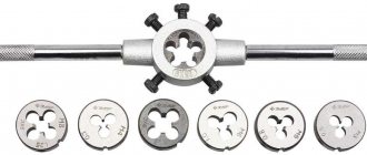
Application of dies
Dies are purposefully used to work with the same hardware in the form of bolts and studs, but only when creating external threads. The area that is planned for slicing is pre-processed and cleaned.
How to cut threads by hand correctly and without wasting a tool
The technological process of thread cutting is divided into several operations.
- Preparation. Using the correspondence table, select a drill of the required diameter and accurately drill the hole, preventing the drill from slipping. The drill must be sharpened correctly, otherwise the material will overheat and the thread strength will decrease. Countersink the hole. In case of a blind hole, give an allowance for depth.
- To cut threads, use taps of standard sizes only.
- Slicing. Movements should be neat and measured. Do not skip numbers; all three should be used sequentially - from rough to final.
- After each full turn, the driver should be given a half turn in the opposite direction to chip the chips and push them out of the grooves.
- Cleaning. Pass-through holes are cleaned with a wire brush, blind holes are cleaned with an industrial vacuum cleaner or a stream of compressed air.
- Examination. Screw the screw into the hole. It should fit in without distortion and follow the thread smoothly and effortlessly.
Sequence of thread cutting with a tap
There are other secrets of hand-cutting in folklore, but to obtain high-quality carving it is enough to strictly follow the above
Features of the technology
The sequence of actions when passing an internal thread using a tap is as follows:
- Mark the hole.
- Hammer it with a hammer and core.
- Lubricate the part and drill.
- Secure the part in a vice or press it to the workbench with a clamp.
- Secure the drill in the machine chuck, set the lowest speed and start drilling; after the drill head is immersed in the metal, you can add more speed.
- Once drilling is complete, remove the chips and countersink the hole.
- Lubricate the tap and the part, align the tap strictly along the axis of the hole.
- Carefully begin the first turns of thread cutting with a tap. After each full turn, make a half turn in the opposite direction. Add lubricant every few turns.
- If the force on the driver increases sharply, it is necessary to move it back to throw off the chips.
- After passing. go through the hole in the same way.
The most important feature when cutting threads is thoroughness, accuracy, lack of haste and unnecessary effort. It's better to spend a few seconds making an extra half-turn back than to spend hours fiddling with a broken and jammed tap, removing it at the risk of damaging the part, and then finding yourself in front of the same hole again.
Slicing technologies
Most often, cutting is done using a mechanical machine. The workpiece is placed on the machine in a vertical position. A mechanical machine processes a workpiece using threaded tools - cutters made of durable iron alloys. Internal cutting is carried out with curved cutters, external cutting is carried out with straight or curved cutters. To obtain the most accurate thread on a mechanical machine, you need to correctly correlate the speed of rotation of the workpiece and the angle of impact of the cutters, taking into account the performance parameters of the machine.
To carry out internal cutting manually, you need to create a hole in the part using drilling.
Cutting is done using taps - rods with cutting edges. Taps are selected based on diameter and pitch, and secured in a vice. Initially, a roughing tap is used to give approximate dimensions. Afterwards, a finishing tap is used, through which the product is given precise shapes in accordance with the specified parameters. The internal thread is made correctly only if the bolts are screwed into the pipe easily and tightly.
Types by design
Taps vary greatly in their design:
- Fluteless have very short grooves and are used for working with tough materials: light metal alloys and some low-carbon high-alloy steels.
- Helical - grooves are arranged in an ascending spiral; they are used to cut threads in blind holes on high-performance machines.
- Stepped. The working part is divided into two zones, the first cuts and the second smoothes.
- a thread is cut into it .
- Broaches. Used for cutting threads in through holes using a lathe.
- With an internal cavity for coolant supply.
- Bell type. They are used for cutting large diameters (up to half a meter) and consist of several cutting systems mounted in a common mandrel.
There are other tap designs for rare and special applications.
Thread cutting with G-code G33/G32
G33 is used for thread cutting, but with it we can only do one thread cutting. All this means that you must do all the work of installing the threading tool yourself.
Operating sequence for G code G33/G32
Here is the sequence of operations for cutting longitudinal threads using G33.
- Move the threading tool to the starting point. (G00)
- Make thread cutting using G32.
- Move the tool back along the x axis (G01 or G00)
- Perform rapid traverse in the Z axis to the thread starting point (G00).
- Move the x-axis tapping tool a little deeper (G01)
- Make a second thread cut using G32.
- And again and again the sequence is repeated until the depth of the carving is complete.
This thread cycle allows us to have complete control over each positioning point, we tend to call it a cycle, it is actually modal because it locks the spindle from rotating at the feed rate, just like a manual lathe does. This gives us the ability to thread a screw when programming from point to point.
Cutting - tapered thread
Cutting a conical thread on a screw-cutting lathe is done using a copy ruler, which is set to a cone angle of 9 - The thread pitch is set in the same way as for cylindrical threads. [1]
READ How to cut ceiling plinths in corners
Taper thread cutting is carried out on machines with a tapered ruler. The bisector of the conical thread profile, according to the standards adopted in the USSR, is perpendicular to the thread axis. The pitch is measured in a direction parallel to the thread axis. The average diameter of a tapered thread in each section perpendicular to the axis has a different value, therefore, on a tapered thread, the measurement plane is set at a distance a from the end. In the measurement plane, the values of the outer, middle and inner diameters of the thread are indicated. [2]
Taper thread cutting is carried out on machines with a tapered ruler. The bisector of the conical thread profile, according to the standards adopted in the USSR, is perpendicular to the thread axis. [4]
It is unacceptable to cut a tapered thread from the side of the untreated surface due to possible size fluctuations from this surface to the measuring base. Therefore, before cutting a tapered thread, the raw surface should be counterseen. [6]
Conical and self-opening taps are used to cut conical threads. [7]
To cut conical threads, heads with large combs are used, designed for cutting cylindrical threads. [8]
Round cutters are usually used to cut conical threads. Rod incisors are used very rarely; but their designs are almost no different from rod cutters for cylindrical threads. [9]
For cutting conical threads with a taper K - y - - it is advisable to use dies with an uneven cutting offset. [10]
To cut conical threads on pipes, pipe cutting chucks are used, installed on special machines. During threading, the chucks rotate, but the pipe does not rotate. [eleven]
Dies of a special configuration are used for cutting conical threads. [12]
To cut conical threads, dies with conical threads are used. [13]
To cut conical threads with a taper k - j, it is advisable to use dies with an uneven cutting offset. [14]
A diagram of cutting conical threads with taps is shown in Fig. In some cases, this scheme is also used for cutting cylindrical threads. [15]
Threaded connections are the most reliable of detachable connections. They were first used in antiquity, and have been significantly improved since then. Before the invention of the screw-cutting lathe in the 17th century, each bolt-nut pair was made individually; they were not interchangeable. In the 19th century, during the development of railways in England, inventor Sir Joseph Whitworth proposed and introduced a threading standard that has since bear his name. For cutting external threads, a screw-cutting lathe or special dies are used; for cutting internal threads, taps, a type of milling cutter, are used.
Thread cutting on a lathe: including with a cutter (photo, video)
Cutting a thread with a cutter on a lathe is not the most technologically complex process, but it requires increased attention, certain skills and theoretical knowledge. It is the latter that we will tell you about, which will allow you to get as close as possible to the desired quality of processing workpieces by cutting threads with cutters.
articles
- 1 Incisors
- 2 Cutting technique 2.1 Rules for obtaining threads
Scheme of cutting threads on a lathe with a cutter
To obtain carvings, craftsmen use different cutters:
- Pipe cutting tools;
- Threading heads;
- Taps;
- Dies.
Due to the design of the lathe, cutting threads on a lathe allows you to obtain internal and external variations in its execution.
In this case, a device that allows you to process wood by cutting threads is divided into three large categories:
- Prismatic group. This cutter can be used to process the outer sides of workpieces. At the same time, the device of the prismatic group allows you to work with large-sized workpieces. The tool is held in the machine holder by a special device called a dovetail. Thread-cutting elements of the prismatic group are subject to multiple regrinding, which makes them stand out compared to rod tools.
- Core group. The simplest device for cutting. The rod can have any cross-sectional shape; it has a working head. Depending on the shape of the head, the profile is determined. A rod jig is a shaped category of woodworking tools. The most popular of them has soldered carbide edges to cut off excess wood. They have a long service life and require sharpening less often than others.
- Round group. The heads of such devices allow you to cut internal and external threads. With such a cutter you can perform a wide range of operations, which is why they compare favorably with the prismatic group. An important feature is the ability to resharpen the tool multiple times without losing its original characteristics.
Slicing technique
Drawing of a thread cutting diagram on a lathe with a cutter
- The operator, controlling the cutter, moves it evenly along the workpiece;
- The working head itself makes a helical line with its top;
- Depending on the inclination of the line to the axis, which is perpendicular to the movement of the working tool, the angle of increase in the helical lines is determined;
- This angle depends on the characteristics of the tool feed and the rotation speed of the workpiece on the lathe;
- When the cutting device is deepened into the workpiece, it is covered inside with helical grooves;
- Using threads, you can provide high-quality fasteners, seal parts, or move elements in the required directions with a given pitch;
- Based on the configuration of the blank, the fastening receives the corresponding name - conical or cylindrical;
- The profile, which simultaneously projects across the diameter of the projection on the surface of the thread, is selected based on the purpose;
- The most commonly used profiles are acute-angled, trapezoidal and rectangular;
- Profiles are cut using a single-pass or multi-pass method;
- Multi-start ones are created from several grooves, which are located at the same distance relative to each other;
- Single-start ones are created by one groove;
- Thread characteristics are determined by pitch and stroke. This is the distance available between identical components of a threaded thread;
- To determine the distance, you need to step by the number of passes.
Rules for obtaining threads
Threading operations require that the master uses conical pipe cutting, cylindrical pipe cutting, inch, and thrust types of thread.
In order for the execution of a pipe cutting structure to proceed correctly and without errors, it is necessary to rely on certain rules when working with a die, head, tap, etc.
- First, the machine itself is configured. Threading and pipe cutting operations cannot be performed efficiently in the absence of equipment that has the appropriate characteristics and capabilities. Setting up involves adapting the device to a specific type of thread, thread-cutting and pipe-cutting heads, taps, and dies used. The setup is carried out according to the instructions for the machine and working tools. It would be a good idea to reinforce your pipe cutting skills with video lessons.
- Next, based on important rules and recommendations, work is done to create a thread with the required parameters.
- The cleanliness of the resulting thread depends on the correct placement of the working tool and its movement relative to the workpiece. To achieve the desired result, it uses a template installed parallel to the center of the turning device on the workpiece. The projection of the cutter and the template are superimposed on one another and the clearance is checked. The cutting tool must be positioned strictly on the center line of the lathe.
- To cut internal threads, use a curved working tool. If you take a mandrel, you can also use a straight tool. External cutting is carried out mainly with bent, but sometimes even, cutters. Cutters are selected based on the type of material being processed and the thread performance requirements.
- The location of the working edges of the cutters depends on the profile to be made. Triangular ones provide for the production of cutting at an apex of 55 or 60 degrees for inch and metric threads, respectively.
- The selection of the rake angle of the cutter is made based on the workpiece material. It can range from 0 to 25 degrees. In this case, a smaller angle is chosen for harder and more brittle materials.
- The lateral angles of the tool at the rear must have such parameters that when cutting, the lateral elements do not touch the surface of the thread. In most cases, the left and right sides are the same. So, if the thread angle is more than 5 degrees, the side angles will be 6-8 degrees, or 3-5 degrees if the thread angle is less than 4 degrees.
- Internal grooving is done after boring or drilling a hole. During processing, the metal is subject to deformation, which is why the diameter of the hole should be chosen slightly larger than the internal diameter. For a brittle metal, add 0.02 to the value, and for a tough metal, up to 0.4.
- Sometimes the pipe threading machine requires you to complete the cutting with grooves. The internal diameters are made 0.3 millimeters smaller compared to the same thread parameter.
- When using a pipe cutting unit in order to obtain high-quality cutting at the end, make a ledge of 3 mm (no more), without changing the diameter. This protrusion will mark the finishing pass of the cutting tool. When the job is complete, the ledge can be removed.
- Roughing using a cutting head is carried out at a speed of no higher than 30 m/min. Finishing allows the head to rotate at speeds of up to 55 m/min.
- Working with cast iron involves passing the cutting threading head at a speed of up to 25 m/min. For carbide materials this figure is up to 150 m/min.
- If the thread pitch is less than 2 mm, the work is performed at higher speeds, but decreases with a pitch of 6 mm.
- The thread is cut on a lathe using several approaches. Upon completion of each approach, the cutting tool returns to its starting position.
Materials for the production of taps
cutting during its operation , while a machine tap can cut many thousands of holes. Therefore, high-quality tool steels are used for their manufacture:
- For manual models - high-carbon U10A or U 12A.
- For machine machines - high-speed cutting PM5, etc.
- For high-performance automatic equipment - carbide with increased heat resistance.
In addition to the advantages of high performance and durability, such materials also have one drawback - in the event of a breakdown, the tap for threading cannot be drilled.
Preparing to cut internal threads
In order for the thread to be cut without problems, it is necessary to carefully prepare the hole.
The drill must match the material of the part and be properly and well sharpened. The sharpening angle should be no more than 140°. This avoids overheating and involuntary heat treatment of the part material, leading to deterioration in thread quality.
The drill must be carefully secured; it is necessary to prevent runout of both the drill in the chuck and the chuck itself.
When drilling blind holes, you need to carefully control the depth and be sure to give an allowance in depth relative to the specified cutting depth - even the best tap will not cut the thread to the end.
You will need the following tools and supplies:
- Low speed drilling machine. The use of hand drills is not recommended.
- Drill selected according to the table.
- A drill of a larger diameter (about twice as large) for countersinking.
- Set of taps with a collar.
- Vise for securing the part.
- Core and hammer.
- Mineral oil to lubricate the tap and hole during operation.
- Wiping material.
READ On Which Side of the Board Should You Cut?
The rules for cutting pipe threads generally coincide with those stated above, only for cutting large diameters special equipment is used for more accurate alignment
Stages of thread cutting with a machine-hand tap
- The first step is marking in accordance with the drawings.
- According to the marks, punching is carried out with a sharply sharpened core.
- Drill with medium pressure at low speeds. The drill should be at right angles to the surface. Before starting work, the drill is lubricated. If the hole depth is large, then lubrication is carried out not only before starting, but also during operation. The depth of the blind hole should be slightly greater than the length being cut. If there is no reserve, the thread may be incomplete.
- The quality of the result can be improved by countersink processing, which reduces the taper and ensures parallelism of the side surfaces.
- The tap is secured in the driver, its tip is lubricated and inserted into the hole strictly at right angles to the surface. Make the first turn, lightly pressing the knob from above. After the first turn forward, make a half turn back to remove chips. Particular care is taken when using a multi-tool - it is fragile and easy to damage. It's easier to work with complete models.
How to correctly determine the hole diameter?
Before cutting a thread, a hole is made, the diameter of which is determined according to standardized tables. If you prepare a hole whose cross-section is smaller than the recommended size, the tool will fail; if it is larger, the result will be of poor quality.
| Thread designation | Diameter, mm | Thread designation | Diameter, mm | Thread designation | Diameter, mm |
| M 2 | 1,6 | M 8 | 6,7 | M 22 | 19,4 |
| M 2.2 | 1,75 | M 9 | 7,7 | M 24 | 20,9 |
| M 2.5 | 2,05 | M 10 | 8,5 | M 27 | 23,9 |
| M 3 | 2,5 | M 11 | 9,5 | M 30 | 26,4 |
| M 3.5 | 2,9 | M 12 | 10,2 | M 33 | 29,4 |
| M 4 | 3,3 | M 14 | 12,0 | 31,9 | |
| M 5 | 4,2 | M 16 | 14,0 | M 39 | |
| M 6 | 5,0 | M 18 | 15,4 | M 42 | 37,4 |
| M 7 | 6,0 | M 20 | 17,4 | M 45 | 40,4 |
| Thread size, inches | Diameter, mm | Thread size, inches | Diameter, mm |
| 1/8 | 8,8 | 7/8 | 28,1 |
| 1/4 | 11,7 | 1 | 30,5 |
| 3/8 | 15,2 | 1 1/8 | 35,2 |
| 1/2 | 18,9 | 1 1/4 | 39,2 |
| 5/8 | 20,7 | 1 3/8 | 41,6 |
| 3/4 | 24,3 | 45,2 |
size table
The tabular regulation GOST 6111-52 establishes the size and other characteristics of cutting. The following table shows the values of this GOST for inch tapered threads with a profile angle of 60°:
| Thread size, inch | External diameter, mm. | Average diameter, mm. | Inner diameter, mm. | Number of threads per 1 inch | Pitch, mm. | Profile height, mm. |
| 3/16 | 4,67 | 4,14 | 3,11 | 24 | 1,25 | 0,78 |
| 1/4 | 6,24 | 5,43 | 4,84 | 20 | 1,33 | 0,92 |
| 5/16 | 8,72 | 7,58 | 6,27 | 18 | 1,58 | 1,01 |
| 3/8 | 9,81 | 8,93 | 7,51 | 16 | 1,64 | 1,23 |
| 7/16 | 11,53 | 10,21 | 8,84 | 14 | 1,95 | 1,34 |
| 1/2 | 12,36 | 11,16 | 10,49 | 12 | 2,24 | 1,46 |
| 9/16 | 14,45 | 13,57 | 11,636 | 11 | 2,24 | 1,46 |
| 5/8 | 15,54 | 14,72 | 13,31 | 10 | 2,43 | 1,53 |
| 3/4 | 19,26 | 17,43 | 15,83 | 9 | 2,61 | 1,75 |
Despite the fact that now inch tapered threads are not widely popular among ordinary manufacturers, they are used in the production of components for a variety of electrical equipment.
This type has many advantages compared to metric threads. It has a durable and lightweight structure. And in the future, its potential will be revealed in many industries, especially in the production of plastic and metal connecting mechanisms.
If you find an error, please select a piece of text and press Ctrl+Enter.
Types by purpose
According to their purpose, the following types of taps are distinguished:
- Locksmiths. Designed for manual use, they have a square shank. They are supplied complete with a crank, which ensures rotation of the tool and cutting threads. They are used as part of a set of two or three taps, slightly different in diameter. Each person removes their own part of the allowance from the surface of the hole. Inside the set, tools are distinguished by the number of lines engraved or stamped on the shank; the roughest, rough one has one line, the intermediate one has two and the finishing one has three.
- Machine or machine-manual. With such taps, cutting is carried out both manually and using equipment. Lathes, drilling machines or machining centers are used. Unlike metalworking machines, they have a shorter intake part, since alignment is ensured by the design of the machine. Made from higher quality tool steel, heat-resistant and resistant to mechanical loads.
- Nuts. Designed for cutting threads in nuts in automatic machines. Structurally they differ in a longer shank of a smooth cylindrical shape. After passing the thread, the nuts are moved one by one to the shank, and the entire series is expected to be completed there. At the end of the group operation, the shank is removed from the chuck, and all the nuts are shaken off into the receiving tray.
Inch and metric taps are also produced and used separately.
Adapter (pneumatic). How to incorrectly cut a tapered thread with a tap
Sources:
https://ingener-pto.ru/2019/12/12/kak-narezat-konicheskuju-rezbu-metchikom/