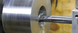
Thread cutting on a lathe is one of those operations for which various tools can be used. This problem is most often solved using a cutter. In addition to it, taps, dies, and special-purpose working heads are also used. In addition, on lathes this operation can be performed using knurling technology.
The process of cutting threads on a lathe with a cutter
Types and properties of cutters
Classification
In practice, cutters for external and internal threads with a rectangular section holder are used. Less common are disc, prismatic, sharpened along the front surface. The working profile of all corresponds to the dimensions of the screw groove. In the direction of the cut spiral, left and right ones are released.
There are solid and prefabricated instruments. The first ones are mainly made of high-speed steel, small section or disk. The bulk is equipped with cutting plates secured by soldering with refractory solder or mechanically, allowing replacement when worn.
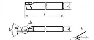
Threaded cutters: external (Fig. 1), internal (Fig. 2)
Thread cutting with cutters
On screw-cutting lathes, the most widely used method is cutting external and internal threads with cutters (Fig. 4.45). Threading cutters are rod, prismatic and round; their geometric parameters do not differ from the geometric parameters of shaped cutters. Triangular profile threads are cut with cutters with a leading angle at the apex ε = 60° ± 10′ for metric threads and ε = 55° ± 10′ for inch threads. Taking into account the errors in the movement of the caliper, which can lead to an increase in the thread angle, cutters with an angle ε = 59°30′ are sometimes used. The tip of the cutter can be rounded or chamfered (in accordance with the shape of the root of the thread being cut).
Threading cutters are equipped with plates made of high-speed steel and hard alloys. The part is first ground so that its outer diameter is smaller than the outer diameter of the thread being cut. For metric threads with a diameter of up to 30 mm, this difference is approximately 0.14 ... 0.28 mm, with a diameter of up to 48 mm - 0.17 ... 0.34 mm, with a diameter of up to 80 mm - 0.2 ... 0.4 mm. The reduction in the diameter of the workpiece is due to the fact that when cutting a thread, the material of the workpiece is deformed and, as a result, the outer diameter of the thread increases.
Threading in a hole is carried out either immediately after drilling (if high demands are not placed on the accuracy of the thread), or after boring it (for precise threads). Hole diameter (mm) for thread
d0 = dP,
where d is the outer diameter of the thread, mm; P — thread pitch, mm.
The diameter of the hole for the thread should be slightly larger than the internal diameter of the thread, since during the threading process the metal is deformed and, as a result, the diameter of the hole decreases. Therefore, the result obtained from the above formula is increased by 0.2...0.4 mm when cutting threads in viscous materials (steel, brass, etc.) and by 0.1...0.02 mm when cutting threads in brittle materials ( cast iron, bronze, etc.).
Depending on the requirements of the drawing, the thread may end with a groove for the cutter to exit. The internal diameter of the groove should be 0.1 ... 0.3 mm less than the internal diameter of the thread, and the width of the groove (mm)
b=(2…3)P.
In the process of cutting bolts, studs and some other parts, when the cutter is removed, as a rule, a thread run-out is formed.
For more convenient and accurate thread cutting, a shoulder 2...3 mm long is made at the end of the workpiece, the diameter of which is equal to the internal diameter of the thread. This shoulder is used to determine the last pass of the cutter; after threading is completed, the shoulder is cut off.
The accuracy of the thread largely depends on the correct installation of the cutter relative to the center line. In order to install the cutter along the bisector of the thread profile angle perpendicular to the axis of the workpiece, use a template, which is installed on the previously machined surface of the part along the line of the centers of the machine. The cutter profile is combined with the template profile and the correct installation of the cutter along the clearance is checked. Threading cutters should be installed strictly along the center line of the machine.
On screw-cutting lathes, threads are cut with cutters in several passes. After each pass, the cutter is retracted to its original position. Using the vernier of the lead screw of the transverse feed movement of the caliper, set the required cutting depth and repeat the pass. When cutting threads with pitches up to 2 mm, the feed is 0.05...0.2 mm per pass. If a thread is cut simultaneously with two cutting edges, the resulting chips become tangled and deteriorate the quality of the thread surface. Therefore, before the working pass, the cutter should be shifted by 0.1...0.15 mm alternately to the right or left, using the movement of the upper support, as a result of which processing is carried out with only one cutting edge. The number of roughing passes is 3...6, and finishing passes - 3.
Materials
For the manufacture of the cutting part are used:
- high-speed steels;
- hard alloys;
- mineral ceramics;
- superhard tool materials (STM).
The former are used for thread cutting of steels, non-ferrous metal alloys, and plastics. They are distinguished by high strength, thermal conductivity, but lower, compared to others, hardness, red-hardness, wear resistance, which limit the cutting speed.
The largest proportion of thread cutters used are those equipped with carbide inserts. This is due to high durability, hardness, sufficient strength and rigidity, and reasonable cost. Processing productivity is 2-3 times higher than with rapid. A wide range allows you to select the optimal grade for processing in most cases. Ceramics are relatively cheap, quite fragile, and are used for processing fine pitch threads of steel and cast iron parts, with a rigid AIDS system, with limited allowance removal per pass.
STMs based on polycrystalline diamond (PCD) or cubic boron nitride (CBN) are extremely hard, heat-resistant, but expensive. Indispensable for precision work on difficult-to-cut materials. PCD is used for cutting copper, aluminum, and tungsten carbide. CBN work on hardened steels and hardened cast irons. Successful application requires high rigidity and smooth running of the equipment.
Threaded turning tools - how to buy or order?
Thread turning tools
you can buy from an official supplier of metal-cutting tools at a competitive price from a warehouse in the city of Rostov-on-Don. Tools for cutting threads on a lathe - holders and cutting inserts presented on the site will help you solve the processing issue, but how to make the right choice and order a cutter?
With the help of our company’s specialists, you will be able to correctly select a threaded turning tool and the corresponding insert, choose a processing strategy, adjust cutting modes and find out the number of turning passes. You can also select the tool you need on the website using filters, adding it to your cart and placing an order.
Our company supplies tools for thread cutting from manufacturers: Kennametal (USA), Iscar (Israel), ZCC-CT (China), Gesac (China). The main warehouse of products is located in the city of Rostov-on-Don. Shipment of ordered products is carried out by transport companies Business Lines, PEC or courier delivery services DPD, PonyExpress, SDEK.
Delivery time for custom tools from the manufacturer Kennametal - warehouse in Germany 14-17 days, warehouse in the USA 21-25 days; ZCC-CT - warehouse in Germany 10-12 days, Iscar warehouse in Israel 17-21 days, Moscow warehouse 3-5 days.
Threaded turning cutters are designed for cutting threads from the outer and inner sides of workpieces made of steel, stainless steel, cast iron, titanium, heat-resistant, non-ferrous alloys and others. The universal carbide alloys from which cutting threaded inserts are made have a strong structure and wear-resistant coatings. The presence of a chipbreaker ensures good chip breaking and the quality of the machined surface.
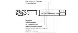
Decoding the writing of threads
Regulatory documents: GOST, OST, MN for a specific type contain samples of conditional recording.
Graphic materials are designed in accordance with the instructions of GOST 2.311-68 “Image of threads”.
A typical designation structure contains:
- the literal part defining the type;
- numbers corresponding to the nominal size in millimeters or inches;
- pitch (mm) is indicated only as fine, after the “×” sign;
- for multi-start ones, instead of the previous paragraph, the stroke (mm) is given, then the step in parentheses;
- direction: right is the default, left is LH;
- tolerance range or accuracy class;
- make-up length other than normal.
Example 1: М16×1.5LH–6H. Explanation:
- M – metric cylindrical;
- 16 – nominal diameter, mm;
- 1.5 – fine pitch, mm;
- LH – left;
- 6Н – tolerance range, where 6 – degree of accuracy; H – main deviation. Capital letters are used for internal (nuts), hence the threads in the hole.
The screw-in length is not indicated, which means it is normal.
Example 2: G1/2–A
- G – cylindrical pipe;
- 1/2 – thread size, inches; corresponds to the internal diameter of the pipe;
- A – accuracy class.
The designation options are illustrated below.
Thread cutting with dies and taps
Dies are used to cut external threads on screws, bolts, studs and other parts. The area of the part where it is necessary to cut the thread with a die is pre-treated. The diameter of the machined surface should be slightly smaller than the outer diameter of the thread. For a metric thread with a diameter of 6...10 mm, this difference is 0.1...0.2 mm, with a diameter of 11...18 mm - 0.12...0.24 mm, with a diameter of 20...30 mm - 0.14...0.28 mm. To form a thread entry at the end of the part, it is necessary to remove a chamfer corresponding to the height of the thread profile.
The die is installed in a die holder (chuck), which is secured in the tailstock quill or turret socket. Cutting speed v when cutting threads with dies for steel workpieces is 3...4 m/min, for cast iron - 2...3 m/min and for brass - 10...15 m/min.
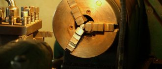
Internal metric threads with a diameter of up to 50 mm are often cut with taps. Typically, a lathe uses machine taps, which allows threads to be cut in one pass. For cutting threads in parts made of hard and viscous materials, sets consisting of two or three taps are used. In a set of two taps, the first (roughing) does 75% of the entire work, and the second (finishing) brings the thread to the required size. In a set of three taps, the first (rough) does 60% of the work, the second (semi-finish) - 30%, and the third (finish) - 10%. The taps in the set are distinguished by the intake part; the intake part of the rough tap has the greatest length.
When installing a tap in a turret, a ring is put on its shank and secured with a screw, together with which the tap is installed in a chuck for dies and secured like a die.
Cutting speed v when cutting threads with taps for steel workpieces is 5... 12 m/min, for cast iron, bronze and aluminum - 6...22 m/min. Thread cutting is carried out with emulsion or oil cooling.
Slicing rules
The quality of the profile depends on many factors:
- Workpiece errors. Underestimation or overestimation of the diameter of the rod and hole, respectively, is the reason for the incomplete height of the turns. The difference in height along the length is a consequence of the taper of the original surface.
- A torn surface is caused by a dull tool, high speed, or incorrectly chosen lubricant.
- Shrinkage of the nut along the average diameter is typical with similar wear of the tap.
- The stretching of the coils occurs due to the braking of the self-extending mandrel.
- Breaking the nut along the average diameter is possible from a large rake angle, which facilitates the pressing of the tap feathers.
To avoid this you must:
- Choose the equipment and cutting method wisely.
- Prepare the workpiece according to the technological documentation or the instructions in the reference tables.
- Select the correct cutting modes and coolant.
- Set up the machine for processing, calculate and assemble the guitar if necessary.
- Control sharpening and installation of the cutter according to the template.
- Check the first finished parts, make adjustments, and periodically repeat the check in the future.
- Monitor the serviceability of devices and sharpen tools in a timely manner. Thread quality control Providing the required service characteristics of the connection is determined by the compliance of the actual values: outer, inner, average diameters, half of the profile angle, pitch. Checks are performed:
- Calibers. They control thread diameters in mass production.
- Pedometers (threaded templates), micrometers with replaceable inserts. The first to check for clearance are P and α/2, the second are equipped with a set of replaceable inserts for different ratings and are designed to measure the average diameter of bolts. They are used in small-scale workshops, measurements are not accurate.
- Accurate measurement of the average screw diameter is performed using three wires, a micrometer or an optimometer. The error of the latter is up to 2 microns.
- Particularly important parts are checked using instrumental microscopes, which make it possible to reliably determine diameters, pitches, and angles.
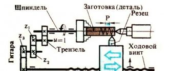
Thread cutting using lathe equipment
When cutting a thread on a workpiece mounted on a lathe using a cutter, the process looks like this: the tool, moving along the axis of the rotating part (feed movement), draws a screw-type line on its surface with its pointed tip. A characteristic parameter of the helix formed by the cutter on the surface of the workpiece is the angle of its elevation or increase. The magnitude of this angle, measured between the tangent located to the helix and the plane, which is perpendicular to the axis of rotation of the part, is determined:
- the amount of feed of the cutting tool moving along the axis of the workpiece;
- the frequency at which the part rotates.
An equally important parameter of the helix is its pitch, which characterizes the distance between its adjacent turns. This distance is measured along the axis of the workpiece.
Moving along the axis of the rotating workpiece, the cutter cuts into it and creates a helical surface, which is commonly called a thread. Elements with a threaded surface are used to solve various problems: ensuring the movement of elements relative to each other, their articulation and sealing of the formed joints.
The most common types of thread profile: a - triangular, b - rectangular, c - trapezoidal, d - persistent, e - round
The surface of the threaded workpiece can be cylindrical or conical. The characteristics of a threaded connection are significantly influenced by the thread profile, that is, its plane contour. Profiles are distinguished:
- triangular;
- trapezoidal;
- rectangular;
- persistent;
- round.
The thread on the surface of the part can be formed by one screw thread (single-start) or several (multi-start). If several screw threads are cut, then they are placed equidistant in relation to each other.
You can count the number of threads at the beginning of the threaded surface. A multi-start thread, in addition to the pitch, is characterized by such a parameter as stroke. This is the distance measured between two similar points of two adjacent turns, which are formed by one thread. This distance is measured along a line parallel to the axis of the threaded part. For a single-start thread formed by one thread, the stroke is equal to the pitch, but for a multi-start thread it can be calculated by multiplying the pitch by the number of starts.
All types of threads with diagrams, parameters and GOST regulations regulating them