The continuous improvement of soldering technology is due to the emergence of more complex printed circuit boards for radio electronics. The infrared soldering station (IPS) is designed to work with a new generation of sensitive microcircuits and other radio components. An unusual approach to soldering is based on the use of a light beam in the infrared range as a carrier of thermal energy.
IPS Achi ir6000
Features and Benefits
The peculiarity of the IR soldering station is that, unlike an induction device, there is no material contact with the radio component; compared to a hair dryer, there is no air flow pressure. The entire soldering process takes place completely in non-contact mode.
The advantages of IPS include the following:
- unlike other designs, an infrared soldering iron provides quick installation or, conversely, removal of solder under conditions of complete control of the heating level of the radio component being processed;
- a focused beam of infrared radiation allows you to precisely direct the thermal energy flow to the desired location on the board;
- IPS makes it possible to set a mode of stepwise increase in heating temperature in the working area;
- infrared soldering reliably restores the broken connection between the microcircuit pad and the printed circuit board;
- The absence of solder and flux in the operation of the station allows you to keep the workplace clean and not clog the board with drops of tin and additive crystals.
Soldering gun design
A soldering gun is often used to melt or soften tin, small sheets of metal or plastic. This treatment occurs due to the blowing of the material with a highly heated spiral. The air becomes very hot and transfers thermal energy to the material being processed.
In order to make such a universal product with your own hands, you need to study its design features. It includes:
- tube-shaped body;
- an air blower, which can be a regular fan or pump;
- manual switch;
- comfortable handle.
Experts recommend additionally equipping a homemade soldering gun with a temperature sensor and several special attachments.
Types of IPS
Based on the type of infrared emitter, there are two types of IPS:
- Ceramic;
- Quartz.
Ceramic
Soldering station for Arduino
An example of a ceramic infrared soldering station is the Achi ir6000 model. The station has a lot of advantages. It has proven itself to be reliable, durable and durable equipment. The operating temperature in the soldering zone is reached within 10 minutes. Stations of this type use a solid flat or hollow ceramic emitter.
Quartz
Unlike a ceramic soldering iron, a quartz station reaches maximum heat in 30 seconds. Quartz stations are very sensitive to frequent on-off cycles.
Attention! If the specifics of the soldering mode require several equipment shutdowns over a short period, then it is better to use a ceramic soldering station.
What is a soldering station
This device is also called a soldering machine. This is a set of tools and devices that includes the main elements:
- soldering iron;
- replaceable tip;
- stand;
- thermal hair dryer;
- tin remover;
- adjustment block.
Compared to the price of a traditional soldering tool, this setup costs tens of times more. The station has a number of advantages over a conventional soldering iron:
- the ability to connect more than one soldering iron;
- implementation of precise adjustment with smooth voltage supply, based on a signal from the electronic control unit;
- protection against exposure to static electricity on processed elements;
- overload protection;
- changing nozzles on the working part of soldering irons;
- freeing surfaces from excess solder.
In addition, it protects the operator from electric shock due to the reduced voltage supply to the soldering irons. For professional work or minor single repairs of electronic equipment, this device improves the quality of soldered joints.
Operating principle
To understand the operation of an infrared soldering station, you need to understand the principle of connecting a microprocessor to a printed circuit board. Microcircuits of laptops and various electronic devices do not have output pins. Instead, on their back there is a grid of contact points. The same grid is on the printed circuit board.
Soldering station - operating principle and types
The contacts on both surfaces are covered with fusible balls. During soldering, the microprocessor is heated by an infrared radiator to the melting temperature of the solder. At the same time, the lower surface of the board is heated by heating elements of the station’s lower platform. By heating the contact connections on both sides, quick soldering of the radio component is achieved. Thanks to the narrowly directed heat flow, the high temperature does not have time to spread to other components of the board.
Important! The station, using software, can carry out various stages of temperature control at certain time intervals.
Infrared
It is also quite possible to make an infrared station yourself. For this purpose you will need:
- soldering iron;
- PC power supply;
- car cigarette lighter.
You can use the old power supply. You only need one working line with a voltage of 12 volts. No special power required. The only thing you need for a soldering iron is a wooden handle. It can be used from any other device or made independently. The first step is to disassemble the cigarette lighter to get to the heating element that is located inside. The photo shows what it looks like.
The next task is to attach the cigarette lighter handle to the soldering iron handle. You can use glue for this. Next, you need to drill a hole in the cigarette lighter handle so that the power wires can be fed through the hole. Once the wires are connected, you can assemble the cigarette lighter module with a ceramic spacer, as shown in the photo below.
The entire structure can be secured to the handle using an additional metal plate. When everything is ready, the wires are connected to the power supply to a 12 volt output. The finished version of the mini-station is shown in the photo below.
The station turns out to be compact, so it is easy to transport and can be powered from any source that is capable of delivering 12 volts DC. It could even be a battery, so the station turned out to be completely autonomous. If you assemble a small block of 18650 lithium-ion batteries with a 12-volt converter and install a charging controller, then the price of such a station will not be.
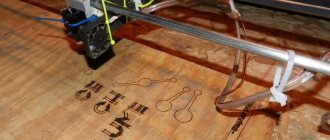
The mini-station heats up almost instantly, and the maximum temperature can exceed 400 degrees. Small elements such as capacitors and transistors can be desoldered, as can be seen in the photo below.
The distance to the board when soldering must be at least 10 mm. In addition to miniature SMD elements, the station can easily cope with microcircuits in SOEC packages. The photo below shows direct evidence of this.
You can also desolder larger components without much difficulty. The station can be slightly modified to make it a convenient option for work. One of the modules that is easy to use additionally is a dimmer, as can be seen in the photo below.
Its purpose is to be able to adjust the power of the soldering station. As a power source, you can use not a power supply from a PC, but a power supply for an LED strip, as can be seen in the photo below. It is easy to purchase at any electrical goods store. The total power of the station is approximately 50 W, the current required for its operation reaches 6 amperes. This should be taken into account when choosing a power supply.
The disadvantage of such a soldering station can be considered the lack of contact with the element that is being soldered. Because of this, there is no way to remove excess solder, and it is also impossible to correct the part if it was positioned offset and the solder has not yet cooled. It is advisable to provide a separate power button on the handle, which will prevent the cigarette lighter from overheating. While operating such a station, it is necessary to hold the manipulator at an angle of 90 degrees to the element that is being soldered. This will make it possible to influence it evenly with the entire area of the heater.
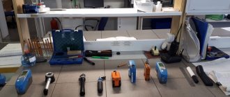
Additionally, for successful soldering of small elements you will need a set of tweezers. Their jaws must be sharp to make it easier to grip miniature components. In addition, you cannot do without a device called a “third hand”. There are many variations of it, but the main purpose is the same everywhere. It consists of holding soldered wires or entire microcircuits. To make it easier to see small components, you need a good magnifying glass or microscope. An integral part of the master's toolkit is good lighting. It would be desirable if it were based on LEDs that do not flicker during operation. When soldering using a station, you cannot do without flux. This is a special solution that improves adhesion and cleans the metal for soldering. A variant of an infrared soldering station with bottom heating can also be assembled independently. There is a video about this below.
Description of the IR soldering process
Induction soldering station
The infrared soldering process consists of several phases:
- The printed circuit board is placed on the station platform.
- It is fixed with side stops and additional slats.
- Around the installation area, the plastic elements are covered with adhesive foil.
- An infrared emitter is installed at a height of 3-4 cm from the microcircuit.
- The thermocouple on a flexible tube is brought directly to the soldering site.
- Using the buttons on the thermal controller interfaces, the operating modes of the upper and lower heaters are set.
- A lamp is connected to the soldering point on a flexible steel cord.
- Turn on the station by pressing the start button.
- After a specified time, the microprocessor is removed from the board using tweezers.
- In the same way, only in reverse order, install a new microprocessor.
Types of stations
All soldering stations can be divided into two large groups:
- hot air;
- infrared.
Each of them is tailored to its own tasks. In most cases, professional repairs require both types of soldering stations. The first is a small block that has one or two manipulators. A hot air soldering station can include only a hair dryer or a hair dryer with a soldering iron. There are soldering stations that only have a soldering iron as a manipulator. Usually these are the varieties that are called induction. In conventional hot-air stations, the soldering iron is heated by a ceramic or similar element to which voltage is applied. This element transmits temperature to the tip. In induction soldering stations, heating occurs due to the action of an electromagnetic field. The energy is immediately transferred to the sting.
Thanks to this approach, it was possible to reduce the inertia of the soldering station, increase the response time, and also increase power with smaller dimensions. In those products that contain heat-intensive elements, it is impossible to do without an induction station, since it is capable of heating large areas of tin in a short time. In some cases, this is difficult to achieve even with a hot-air hair dryer. Induction units are several times more expensive than conventional stations, but their efficiency guarantees pleasure and high precision when working.
Infrared soldering stations are a separate division. In appearance, they are practically different from the two previous types. They consist of two main modules:
- head or top heating;
- bottom heating.
Heating in them occurs due to infrared elements. Thanks to the bottom heating, the board is heated evenly, which avoids deformation when removing or sealing certain elements. Most often, infrared stations are used to replace chips with BGA soldering. They are chip-crystals that are fixed on the board using special solder balls. Some types of such chips can be replaced with a conventional hot air station, but the quality will suffer. The cost of a good infrared station starts from one thousand dollars.
Note! There is a separate subtype of infrared stations, in which the infrared element is placed in a manipulator that resembles a hair dryer. Such products are not widely used and are rarely used.
Design features
The infrared soldering station is a fairly large piece of equipment:
- width – 450-475 mm;
- height – 430-450 mm;
- depth – 420-450 mm.
- the height of the IR emitter support stand is 200 mm.
Additional Information. Dimensions of different station models may vary slightly from the above data. The desktop area is designed for printed circuit boards of maximum size and any configuration.
Location of controls and moving parts of the IR station:
- The work table is a deep platform made of a series of heating elements, covered with a metal mesh.
- Parallel stops with clamps move along guides. They clamp the printing platform on both sides.
- The cross sides are equipped with screw supports that support the board at the desired height.
- The kit includes rails that additionally secure the board.
- A rotating mechanism is installed on the vertical support, on which the infrared heater is fixed.
- The IR emitter can move in a straight direction along the tripod guides. At the same time, the soldering iron can rotate around the vertical support.
- On the front panel of the equipment there are:
- power button;
- thermocouple connector;
- stop button;
- desktop fan key;
- backlight switch;
- top cooling button;
- thermal controller for bottom heaters;
- programmable controller of the upper IR heater.
The temperature of the upper IR heater can reach from 220 to 270 degrees. The lower platform warms up to 150-1700 C.
Contactless soldering iron
If there is no urgent need to use an infrared soldering station, then an infrared soldering iron can be successfully used for soldering. Outwardly, it is similar to a regular one, with the difference that instead of a sting it has a heating element.
Application and device
An infrared soldering iron is used in conditions where contact with component leads is unacceptable. It is also convenient to use it for soldering radio components, since often with a regular soldering iron carbon deposits form on the tip and the connections are of poor quality. The carbon deposits have to be cleaned off, and these actions sometimes take quite a lot of time.
In a home workshop, you can make a simple homemade infrared soldering iron from a car cigarette lighter. The heating element of this device is perfect for making tools.
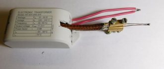
Since normal operation of the cigarette lighter requires a direct current of 12 Volts, corresponding to the on-board electrical network of the car, you will need an electrical converter so that you can use a household AC network. For these purposes, you can successfully use a power supply for computer cases.
Manufacturing
To assemble the infrared soldering iron, you need to remove the heating element from the cigarette lighter housing. Next, you need to connect the power wires to its contacts. Any insulated copper wire can be connected to the central contact corresponding to the “plus” of the automotive network.
A single-core copper wire with a cross-section of at least 2.5 square meters must be connected to the “jacket” of the element in contact with ground in the car. mm. You can already solder another flexible copper conductor to this wire.
The connection must be insulated at a distance of approximately 2-3 cm from the heating element by placing a heat-shrink tube over the connection. PVC insulating tape should not be used as it may melt.
For the body of the infrared soldering tool, you must use any rod made of refractory material. You can even use a faulty soldering iron by attaching the cigarette lighter heating element to the tip.
For this purpose, steel tightening clamps are used. In this case, it is necessary to ensure that the two supply wires do not touch each other with uninsulated sections. The device is connected to the power supply with a flexible cable or power cord of sufficient length.
DIY making
The high cost of an IR soldering station (60-150 thousand rubles) encourages home craftsmen to manufacture such equipment on their own. If you have some experience, making a homemade infrared soldering iron with your own hands is quite possible. Material costs usually do not exceed 10 thousand rubles. You need to prepare the materials and components necessary to assemble the IR station.
Parts for a homemade device
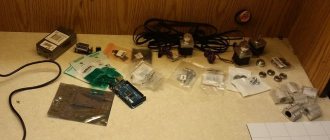
To assemble an infrared soldering station with your own hands, you will need the following:
- sheet of tin;
- flexible spiral metal lamp tube;
- lever tripod from an old table lamp;
- halogen lamps;
- galvanized fine mesh;
- aluminum profile in the form of narrow slats;
- 2 thermocouples;
- Arduino Mega 2560 R3 board;
- SSR 25-DA2x Adafruit MAX31855K board – 2 pcs.;
- DC adapter 5 volts, 0.5 A;
- wires.
Assembly
Installation of a soldering station consists of several stages:
- Thermal table;
- Infrared heater;
- PID controller on Arduino.
Thermal table
It is advisable to make a heating table with your own hands in an equipped home workshop. The design is a bottom heater consisting of the following components:
- housing, reflector, lamps;
- board fastening system;
- flexible thermocouple tube;
- lamp.
Frame
- The base of the heating table is made in the form of a frame from an L-shaped tin profile. You can bend strips of metal with a corner. Cutouts are made with scissors and the metal is bent along them, connecting the parts with self-tapping screws.
- The opening is covered with a metal mesh. To prevent it from bending, metal rods are pulled over the mesh in the transverse and longitudinal directions.
Installation of metal mesh
- The old halogen lamp is disassembled, freeing the reflector from the lamps. It is cut along the inner perimeter of the body.
- The lamps are returned to their place. The heater is inserted into the support frame from below.
Reflector installation
Board mounting system
The aluminum strip is cut into several sections. Mounting holes are drilled in them.
Two sections of the profile are fixed on the wide sides of the body, in the grooves of which the screw clamps of the transverse rails will move. Everything will become clear from the bottom photo.
Board fastening
Flexible thermocouple tube
A spiral metal tube is installed in one of the corners of the frame, and the thermocouple wires are pulled through. The length of the tube must provide access for the thermocouple to the entire working area of the station.
Lamp
A socket with a five-volt light bulb with a reflector is attached to the end of the flexible tube. The base of the metal hose is attached to the corner of the frame in the same way as in the previous case.
Upper heater
The infrared emitter consists of two elements, these are:
- Ceramic plate in the housing.
- Holder.
Attaching the tripod to the upper heater housing
Ceramic plate in the housing
The plate can be purchased on the electrical market or ordered on the online store website. The main thing is to make a durable case in which free air flow is ensured. How to do this can be seen in the photo.
Additional Information. A computer cooler mounted in the upper plane of the IR plate case will help protect the radio component from overheating.
Holder
A two-piece table lamp bracket is ideal for the holder. The base of the bracket is attached to the station frame. The upper rotary hinge is connected to the body of the upper heater.
PID controller on Arduino
A do-it-yourself IR station must be equipped with a control unit. You need to make a separate case for it. An Arduino board and a PID controller are placed inside. An approximate diagram of the layout of the station control unit parts is visible in the photo.
IR station control unit
The Arduino Mega 2560 R3 microprocessor platform controls the heating modes of the ceramic IR emitter and the thermal table platform. Wires for fans (top and bottom), PID controller, thermocouples and lamp are connected to the Arduino board.
Programming of the soldering station is carried out through the controller interface. Its screen reflects the current heating process of the printed circuit board on both sides.
Homemade IPS
Tester
Thermocouples act as testers. They are ultimately sources of information about the state of the heating level of the back side of the printed circuit board and the top surface of the microprocessor.
Assembling an air soldering iron from a regular one
It’s easy to assemble a hot air gun with your own hands from a simple soldering iron. The question arises, why are we upgrading the soldering iron? The answer is simple: there are often situations in which it is not possible to melt solder with a regular tip.
The design of such a device is simple and anyone can assemble it. To make it, you will need a regular pen with a wooden handle and a standard power of 40 watts. To supply air, you need a source of compressed air. An aquarium compressor is suitable for this.
It is necessary to remove the tip and leave the heating element unchanged. We make a hole in the wall and bring the power wire out through it. We glue a sleeve to the rear end of the soldering iron in which a tube connected to a source of compressed air will be attached. We seal the places where the wires pass.
In the metal part of the device, you need to cover the holes with foil, then wrap it with copper wire - this will increase the heat capacity. To replace the tip, you need to install a steel tube of the same diameter so that it holds well and does not fall out during operation. Such a tool usually allows you to heat the surface up to 300 °C.
The operating principle of a DIY soldering gun is as follows:
The air enters the heating element, the heat capacity of which was increased by wrapping the tube with foil and copper wire. Next, the heated air enters a steel tube installed instead of a tip, and through a hole in it is directed to the heated surface.
The disadvantages of such a device include the fact that there is no way to regulate the temperature and it is not high enough for some metals. It can be increased by changing the airflow. This tool, assembled with your own hands, will allow you to work with some radio circuits, but will not be able to replace professional equipment, such as a soldering station.
Mini soldering station with great capabilities
Such a station can be made, for example, from a plastic medicine jar. This device is very compact. It consists of a tube with a spiral installed inside (you can find one in old capacitors) and a fan.
No handle is required for the station, and the power supply on the controller allows you to adjust the temperature.
Such a tool, assembled independently, is comparable in quality to the original store-bought version.
Work in practice
Before starting work, it is important to properly configure the IR soldering station.
Settings
After fixing the printed circuit board on the heating table and connecting the IR emitter to the microprocessor, they proceed to setting up the operation of the station. This is done using the interface keys of the thermal controllers of the upper and lower heaters.
The display of the bottom heating controller at the top shows the current temperature. Use the buttons on the bottom line to set the final value of the degree of heating of the printed circuit board.
The programmable top heating controller has 10 options (thermal profiles). The thermoprofile reflects the dependence of temperature on time. That is, warming up can be programmed in steps. Each step sets a certain time during which the temperature does not change.
Difficulty in work
Mass-produced infrared soldering stations are easy to use and easy to operate. Difficulties in the operation of the station may arise due to a discrepancy between the actual characteristics of the station and the data in the accompanying documentation. The equipment manufacturer is responsible for this in accordance with the warranty.
For people who repair modern electronic devices at home, a homemade infrared soldering station is a must. Purchasing professional equipment makes sense for workshops where there are large volumes of repair work.
Idea No. 4 – Simple wire version
There is another option for making a miniature soldering iron - using nichrome wire. To do this you will need:
- A piece of nichrome wire. You can remove it from old heating elements, wire resistors, irons, hair dryers, etc. The main characteristic of such wire is its diameter, because it determines the resistance of the coil and, accordingly, the power of the tool being manufactured. You can calculate the required length for your diameter using the formula specified in the instructions for option No. 1. The resistivity of nichrome depending on the diameter is given in the table below.
- A piece of wood with a round cross-section.
- A piece of copper wire with a diameter of 1.5-5 mm, a length of 15 cm.
- A small piece of fiberglass insulation for wires.
- A little plaster. Sold in construction stores, another name is alabaster. Many people have little left over after renovation.
- Wires.
Manufacturing process:
- Drill a hole in the block for copper wire 3 times larger than its diameter.
- Place a piece of copper wire in it so that it protrudes about 5 cm and secure it there with thick plaster putty, let it dry.
- Place insulation on the copper rod, which is the tip, and wind the required amount of nichrome wire, leaving a distance between the turns. Also put insulation on the ends and bring them closer to the handle. Then connect the twists with the wires. Tape them to the handle with electrical tape.
That's all, you have another simple and reliable soldering iron design, made by yourself.
We still recommend using either the first or second option, which is more understandable and easier to manufacture. As for the transformer version, although it is more powerful, it is still not so convenient to use. We hope that these photo instructions were useful for you and finally, we recommend that you watch all the video examples in which the assembly process is discussed in more detail!
Also read:
- How to solder wires correctly
- What tools should an electrician have?
- How to make a mini drill with your own hands
30.04.2019