Real capacitor parameters
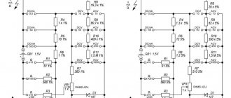
I think you all know that there is nothing ideal in our reckless world. The same goes for electronics. Radio elements, cascades, radio nodes also often fail. You can even recall the recent story with the Progress spacecraft. The failure of some component led to the death of an entire giant in the space industry. Even a seemingly simple radio element, a capacitor, contains not only capacitance, but also other parasitic parameters. Let's look at the circuit, what does our real capacitor consist of?
Where
r is the resistance of the dielectric and the housing between the capacitor plates
C is the actual capacitance of the capacitor
ESR - equivalent series resistance
ESI (more often called ESL) - equivalent series inductance
This is actually what a simple harmless capacitor, especially an electrolytic one, consists of. Let's look at these parameters in more detail:
r is the dielectric resistance. The dielectric can be the electrolyte in electrolytic capacitors, paper or some other crap). Also between the terminals of the capacitor is its body. It also has some kind of resistance and is also made of dielectric and belongs here.
C is the capacitance of the capacitor, which is written on the capacitor itself, plus or minus some deviations associated with the error.
ESI(ESL) - series inductance is the self-inductance of the plates and leads. At low frequencies it can be ignored. Why? Read the article: inductor in direct and alternating current circuits.
Where is ESR hidden in a capacitor?
ESR is the resistance of the leads and plates
As you know, the resistance of a conductor can be found using the formula:
Where
ρ is the resistivity of the conductor
l - conductor length
S is the cross-sectional area of the conductor
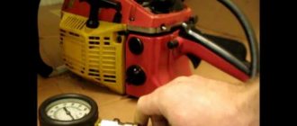
So you can approximately calculate the resistance of the capacitor’s terminals and at the same time its plates. But, of course, no one does that. For this purpose, there are special devices that can measure this very parameter. For example, my device from Aliexpress, which I recently purchased.
How to test a starting capacitor with a multimeter
A starting capacitor is needed for stable operation of the electric motor. It’s easy to check its operation with a multimeter:
- Turn off the power to the air conditioner.
- Discharge the capacitor.
- Remove the terminal.
- Select the capacitance measurement function on the multimeter.
- Select value limit. To do this, as usual, we look at the housing values and set the parameter on the device to a higher value.
- Place the probes against the terminals.
- Let's look at the numbers that appear on the screen.
If the value is different from what is on the case, most likely the mechanism needs to be replaced.
Why is a high ESR value harmful?
Previously, even when the first electronic circuits had just begun to appear, such a parameter as ESR was not even heard of by anyone. Maybe they knew that there was this resistance, but it did not harm anyone. But... with the advent of the first switching power supplies, people began to talk more and more often about ESR. Why did switching power supplies not like such harmless resistance?
At zero frequency (direct current) and low frequencies, as you remember from the article capacitor in a direct and alternating current circuit, the capacitor itself provides great resistance to electric current. In this case, some parasitic Ohm fractions of the ESR resistance will not affect the parameters of the electrical circuit. All the fun begins when the capacitor operates in high-frequency (HF) circuits.
You and I know that a capacitor passes alternating current through itself. And the higher the frequency, the lower the resistance of the capacitor itself. Here's the formula in case you forgot:
where XC is the resistance of the capacitor, Ohm
P is a constant and equals approximately 3.14
F - frequency, measured in Hertz
C - capacitance, measured in Farads
But we didn’t take one thing into account... The resistance of the leads and plates does not change with frequency! So... and if you think about it, it turns out that at an infinite frequency the resistance of the capacitor will be equal to its ESR? It turns out that our capacitor turns into a resistor? How does a resistor behave in an AC circuit? Yes, just like in a DC circuit: it gets hot! Therefore, this resistor will dissipate power P into the environment. And as you remember, power through resistance and current is expressed by the formula:
P=I2xR
Where
I is the current strength, in Amperes
R - ESR resistor resistance, in Ohms
This means that if the ESR is greater, then the power dissipation will also be greater! That is, this resistor will heat up quite well.
Are you catching up on what I’m telling you?
From all of the above, we can draw a simple conclusion: a capacitor with a large ESR in high-frequency circuits with high currents will heat up. Well, okay, let it warm up... Resistors and microcircuits also heat up and nothing! But the whole problem is that as the temperature of the capacitor increases, its capacity also changes! such an interesting capacitor parameter as TKE or Temperature Coefficient E of capacitance. This coefficient shows how much the capacitance changes with temperature changes. And since the container is already “floating”, then the circuit “floats” after it.
First version of the probes
Which, given its rather high cost, you will agree, is not the best option. In my device, a 100 Ohm resistor is connected in parallel to the capacitor being measured, which means that if the capacitor is nevertheless charged, it will begin to discharge when the probes are connected. In the worst case scenario, if the microcircuit used in my device burns out, to make repairs you will only need to remove the microcircuit from the DIP socket and plug in a new one.
ESR electrolytic capacitors
Basically, the ESR parameter concerns electrolytic capacitors. The electrolyte that is there loses some of its properties when heated and the capacitor changes its capacity, which, of course, is undesirable. After decent heating, the capacitor begins to dull, swells and quickly ages.
For swollen capacitors, it is the ESR that first of all increases, while the capacitance can remain practically nominal until a certain time (well, the one that is written on the capacitor itself)
Most often they swell in switching power supplies and on motherboards, usually near the processor (the load on them is higher there, and the heat from the processor probably plays a role). One of the characteristic symptoms: equipment (computer, monitor) begins to turn on worse and worse. Either with a pause (up to several hours after turning on the network), or on the tenth attempt.
Another symptom: if you turn off the power for a while (turn off the power filter, or unplug it from the socket), it starts to turn on again, not on the first try, or after a pause. And if you do not turn off the power, then the computer can turn on immediately (but this is also for the time being, of course). But it happens that the capacitors are not swollen, and the ESR is already tens of times higher than normal. Then, of course, we replace it. From experience, this is a very common problem. And very easily diagnosed (especially if you have a miracle device from your Chinese comrades).
How to test a ceramic capacitor with a multimeter
Ceramic elements are usually without polarities. As we have already mentioned, their verification is almost the same, only the norm of the obtained values differs:
- On the multimeter, select the resistance measurement function.
- We set the maximum measurement limit.
- We touch the multimeter wires to the contacts, but do not touch them ourselves!
If on the display you see a number starting from 2 Mohm, everything is in order. If the value is less, the capacitor is not suitable for further use.
Now you know the most important thing about how to check the health of a capacitor with a multimeter and you can do it yourself.
We wish you safe and accurate inspections!
How to measure ESR
Let's measure some of our Chinese capacitors for ESR. To do this, take our multifunctional universal R/L/C/Transistor-meter and take several measurements:
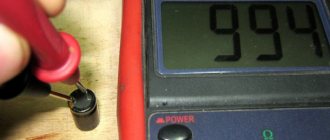
The first to go into battle is a 22 µF x 25 Volt capacitor:
Capacity is close to nominal. ESR=1.9 Ohm. If you look at the plate, the maximum ESR = 2.1 Ohm. Our capacitor falls well within this range. This means it can be used in high-frequency circuits.
The next capacitor is 100 uF x 16 Volts
ESR=0.49 Ohm, look at the plate... 0.7 maximum. That means everything is OK too. Can also be used in RF circuits.
And let's take a capacitor with a capacity of more than 220 uF x 16 Volts
The maximum ESR for it is 0.33 Ohm. Ours showed 0.42 Ohm. Such a capacitor will no longer go into the RF part of the radio equipment. And in simple circuits where low frequencies (LF) roam, it will work just right! ;-).
Final version
Overall, the device turned out to be simply gorgeous and very convenient, and even if the parts for its assembly cost twice as much, I would still be able to safely recommend this EPS meter for assembly to all novice craftsmen who have a modest budget, or who want to save money and don't overpay. Happy repairs everyone! AKV.
- GRAPHIC VOLTAGE ANALYZER
- 4-POINT THERMOMETER
- THREE-PHASE WATTMETER WITH WIFI
Low ESR Capacitors
In our rapidly developing world, electronics are increasingly built on the RF part. Switching power supplies have almost completely triumphed over bulky transformer power supplies. We, radio amateurs, still use homemade power supplies made from transformers that we found in the trash.
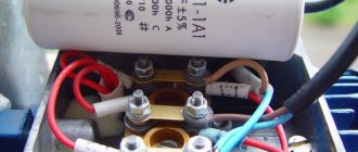
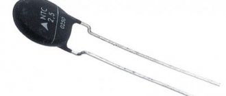
But since almost all equipment goes into the HF range, then the developers of radio components do not sleep either. They create capacitors that have low ESR and are called LOW ESR , which means low ESR capacitors. On some they write this right on the body:
A distinctive feature of such capacitors is that they are elongated. Also, according to my observations, they most often have a gold stripe:
Nowadays, miniature polymer aluminum capacitors with low ESR are increasingly used:
Where can you most often see them? Of course, by disassembling your personal computer. You can find them in the power supply, as well as on the computer motherboard.
In the photo below we see a computer motherboard, which is completely covered with capacitors with LOW ESR, some of which I marked in the red rectangle:
Ceramic and SMD-ceramic capacitors have the smallest ESR
Interesting video on the topic:
A must read!
Before starting the measurement processes, consider the simple but very important rules for testing a capacitor with a multimeter for functionality:
- Only discharged capacitors are allowed to be checked. They accumulate electrical charge, so it is necessary to discharge them. You can use a screwdriver to do this: touch the terminals to create a spark. After this, you can start dialing. By the way, some people use cables and lamps to test the capacitor, but using a multimeter is accurate and reliable.
- If the capacitor capacity is more than 20 µF, you should not even think about a simple short circuit. Include a 5-20K Ohm resistor, which implies one or two Watts, between the contacts. If you do not take this into account, during the discharge there will be a powerful spark, and this is a health risk. Remember that you need to wear safety glasses when interacting with high-capacity elements!
- Before you start measuring, examine the external condition of the capacitor. When the insulation is broken, there are cracks and other defects, it is better to immediately replace it with a working part. If there are no visible problems, you should use a tester.
- It is important to understand the type of capacitor. When it has polarities, it is important to respect them if you do not plan to say goodbye to the device. If non-polar, then you don’t have to define the “-” and “+” outputs.
- To check the capacitance of the capacitor you will have to unsolder it. If you are thinking about how to test a capacitor on a board with a multimeter, you will be disappointed: no way. If you try to measure directly on the board, the process will be affected by other components in the circuit, meaning the readings will be inaccurate. However, certain meters are sold in which the voltage on the probes is reduced, which allows testing even on the board.
There is also a point regarding how to check the capacitor on the board with a multimeter without desoldering it. Without soldering, it is possible to check the possibility of functioning of the element if there is no bridging with a low-impedance circuit. The fault can be checked, for example, using the constant voltage function. That is, if you do not unsolder the element, you can even find out on the board whether the capacitor is working or not.
Video about checking a capacitor with a multimeter without desoldering: