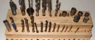
Basic elements of a twist drill
Drilling, countersinking and reaming are the main technological methods for cutting round holes of varying degrees of accuracy and with varying surface roughness.
All of the above methods relate to axial processing, i.e.
to blade processing with a rotary main cutting movement at a constant radius of its trajectory and feed movement only along the axis of the main cutting movement.
Drilling
- the main method of processing holes in solid workpiece material.
Drilled holes, as a rule, do not have an absolutely regular cylindrical shape.
Their cross section has the shape of an oval, and the longitudinal section has a slight taper.
The diameters of the drilled holes are always larger than the diameter of the drill with which they are processed. The difference between the diameters of the drill and the hole drilled by it is called hole breakdown.
For standard drills with a diameter of 10...20 mm, the breakdown is 0.15...0.25 mm.
The reason for the breakdown of holes is insufficient accuracy of drill sharpening and misalignment of the drill and the spindle of the drilling machine.
Drilling holes without further processing is carried out when the required dimensional accuracy is within the 12...14th grade.
Most often, drilling is used to process holes for bolted connections, as well as holes for cutting internal fastening threads into them (for example, with a tap).
Countersinking
is the processing of pre-drilled or cast and stamped holes to produce a more precise shape and diameter than drilling. The accuracy of machining a cylindrical hole after countersinking is 10...11th quality.
Deployment
- this is the final processing of drilled and countersinked holes to obtain cylindrical holes that are precise in shape and diameter (6...9th grade) with low roughness Ra 0.32...1.25 microns.
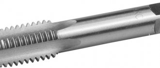
Drill
are intended for drilling through or blind holes in parts processed on drilling, turning-turret and some other machines. Depending on the design and purpose, the following drills are distinguished:
Rice. 2.22.
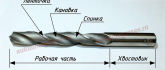
Spiral drills: a and b - elements of a spiral drill, respectively, with conical and cylindrical shanks; c - edges and surfaces of a twist drill; 1 - working part; 2 - neck; 3 - shank; 4 - foot; 5 - cutting part; 6 - leash; 7 - tooth; 8 - helical groove; 9 — transverse edge; 10 — edge of the ribbon; 11 - back of the tooth
Rice. 2.23.
Twist drill angles: α - clearance angle; γ — front angle; Ψ is the angle of inclination of the transverse cutting edge; ω is the angle of inclination of the helical groove; 2φ — apex angle; 1 - rear surface; 2 - front surface; 3 - cutting edge
Rice. 2.24.
Forms of sharpening spiral drills: a - ordinary; b - double: 1 - main cutting edge; 2 - transverse cutting edge; 3 - auxiliary cutting edge; 2φ is the main angle at the tip of the drill; 2φ0 - auxiliary angle at the tip of the drill; Z0—width of the second sharpening zone; c — sharpening the transverse blade and ribbon; g — ribbon point: f — ribbon width
- spiral with cylindrical and conical shanks, designed for drilling steel, cast iron and other structural materials;
- equipped with inserts made of hard alloys, designed for processing parts made of cast iron (especially with casting skin) and very hard and hardened steel;
- deep drilling (single- and double-sided cutting), used when drilling holes whose length exceeds the diameter by five times or more;
- centering tool (centering drills and countersinks), designed for processing center holes of workpieces.
The twist drill and the elements of its working part are shown in Fig. 2.22.
The angles and sharpening shapes of a twist drill are shown in Fig. 2.23 and 2.24. The shapes of drill sharpening are selected depending on the properties of the materials being processed and the diameter of the drill.
To increase the durability of the drill and processing productivity, the drill is double sharpened at angles 2φ = 116...118° and 2φ0 = 70...90° (Fig. 2.24, b). Sharpening the transverse edge (Fig. 2.
24, c) and drill strips (Fig. 2.24, d) facilitates the process of drilling holes.
Sharpening the transverse edge reduces the axial force, and sharpening the band reduces the friction of the bands on the walls of the hole and increases the durability of the drills.
When sharpening, the length of the transverse edge is reduced to 50%. Typically, drills with a diameter of more than 12 mm are sharpened, as well as after each drill resharpening.
Depending on the material being processed, the angles at the tip of the drills are selected according to the table. 2.10, and the rear and front angles - according to table. 2.11.
Carbide drills are used for drilling workpieces made of cast iron and non-ferrous metals. Due to instability, these drills are rarely used when drilling steel workpieces.
Drills with a diameter of 5 to 30 mm are equipped with plates or crowns made of carbide.
in the high temperature zone. Drills with butt-soldered carbide bits are free from these disadvantages.
Table 2.11. Back and front corners of the drill
Notes. 1. Clearance angles are given for cutting edge points located at the largest drill diameter dmax. 2. When calculating the angle γ, take dr= dmax.
For successful operation of carbide drills, it is necessary to ensure their increased strength and rigidity compared to drills made of high-speed steel; this is achieved by increasing the core to 0.25 of the drill diameter.
Countersinks are designed to machine cast, stamped and pre-drilled cylindrical holes to improve surface finish and accuracy or to prepare them for further reaming.
Countersinks are used for final machining of holes with a tolerance of 11...12 grades and provide a roughness parameter Rz of 20...40 microns.
Structurally, countersinks are made with solid tails, assembled tails with insert knives, mounted solids and mounted assembled ones.
Countersinks are made of high-speed steel or with carbide plates soldered onto the body of the countersink or the body of knives in prefabricated structures.
Shank countersinks (like drills) are attached using cylindrical or conical shanks; mounted countersinks have a conical mounting hole (taper 1:30) and an end key to prevent turning during operation.
The countersink (Fig. 2.25, a) consists of a working part l, a neck l3, a shank l4 and a foot e. The working part of the countersink has a cutting l1 and a calibrating l2 part.
Countersinks have three, four, and sometimes six cutting teeth, which promotes better direction in the hole being processed compared to drills and increases processing accuracy.
Rice. 2.25.
Countersink: a - countersink elements: l - working part; l1 - cutting part; l2 - calibrating part; l3 - neck; l4 - shank; e - foot; b - cutting part of the countersink: α - clearance angle; γ — front angle; φ is the angle of the main cutting edge; ω is the angle of inclination of the countersink groove; t—cutting depth; b - cutting edge: φ1 - angle of auxiliary cutting edge
High-speed steel countersinks are manufactured as solid tail ones with a diameter of 10...40 mm, assemblies with insert knives with a diameter of 32...80 mm, or mounted prefabricated ones with a diameter of 40...120 mm.
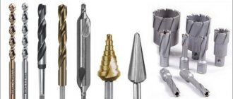
Types of drills: types, purpose, features
Drills are designed to create holes in the material - both through and non-through (recesses).
Drills are produced for a wide variety of materials that are used in production and everyday life: for wood and its composites, metal, concrete, plastic, stone, etc.
Drilling occurs as a result of translational (along the axis) and rotational movement of the drill. The material is cut using cutting edges, which can have different configurations and sharpening angles.
Subtypes of drilling include drilling (making a blind hole) and reaming (expanding an existing hole to a larger diameter).
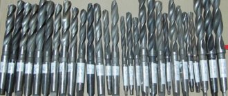
There are many types of drills, differing in purpose, configuration of the working surface, manufacturing method, type of material for which they are intended, etc.
Types of drills depending on the shape of the working surface
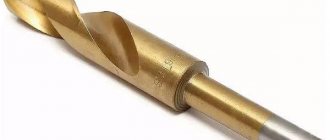
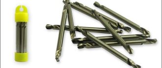
Screw or spiral.
The most popular drill, used for drilling a wide variety of materials. The length of the twist drill can reach 28 cm, diameter – 80 mm.
Advantage
Plexiglas is a very light material, but with high viscosity.
On the one hand, in cases where the appearance of the hole does not matter, you can drill it with an ordinary nail inserted into a drill. On the other hand, when smooth, smooth edges and high precision are required, great care is needed. Unlike a conical drill or a countersink drill, a twist drill, as a rule, operates at high speed - up to 10,000 rpm. At this speed, the material heats up and partially deforms. Matte edges, for example, are an inevitable result of drilling. If you do not follow the rules for handling the tool - cooling, removing chips, the drill can be broken.
When drilling plexiglass, the viscous material wraps around the tip and freezes, rotation is blocked. If the tool is not turned off, the drill is likely to be broken. In addition, it is almost impossible to remove a broken fragment from a mass of glass without cutting it.
However, using a properly sharpened tool will ensure that you get straight, accurate holes and will not require drilling or countersinking later.
Basic elements of a twist drill - Machine tools, welding, metalworking
Rice. 1 Drill parts
Main parts of the drill.
Cutting part (Fig. 1). Calibrating (guiding, transporting) part. These two parts form the working part of the drill. The connecting part (neck). Tail part.
Working part
together with the cutting and calibrating parts, it forms two helical grooves and two teeth (feathers) that ensure the cutting process.
Calibration part
drills designed to remove chips from the cutting zone. The calibrating part has a ribbon along its entire length and, together with it, serves to guide the drill in the hole.
Neck
For drills, it is used to release the grinding wheel, as well as to mark the drills.
Tail section
It can be cylindrical or conical with a Morse taper. At the end of the tail there is a leash or paw.
Drill components
The drill has a complex structure and is characterized by the diameter and length of the drill, the width and height of the ribbon, the diameter of the back, the central angle of the groove, the width of the tooth (feather) and the diameter (thickness) of the core.
Drill diameter
(d) .
The choice of drill diameter depends on the technological process for producing the hole.
Drill strip.
Provides direction for the drill during the cutting process, reduces friction on the surface of the hole and reduces heat generation.
The width of the ribbon varies from0,2–2
mm depending on the diameter of the drill. Choose the width of the ribbon:
when processing light alloys equal
f =1.2+0.2682 ln { d -18+[( d -18) 2 +1] 1/2 }
;
when processing other materials
f =(0.1…0.5) d 1/3
.
The height of the ribbon is usually 0.025 d
mm.
To reduce friction when working on tapes, thinning is done in the direction of the shank, i.e. reverse taper in diameter for every 100 mm of length. For high-speed drills, the reverse taper in diameter is 0.03-0.12 mm. For carbide drills – 0.1-0.12 mm.
drill core
affects strength and rigidity, characterized by core diameter –
d o
. The core diameter is selected depending on the diameter of the drill. To increase the rigidity and strength of the drill, its core is thickened towards the shank by 1.4-1.8 mm for every 100 mm of length.
The drill bridge influences the cutting process.
Drill cutting elements.
The working part of the drill (see figure) has six blades (cutting edges).
Two main cutting edges
(1-2, 1'-2').
Two auxiliary edges
(1-3,1'-3') located on the calibrating part and serving to guide the drills during operation.
Two transverse edges
(0-2, 0-2') forming a bridge.
All these blades are located on two teeth and have a continuous spatial cutting edge, consisting of five differently directed segments (3-1, 1-2, 2-2', 2'-1', 1'-3').
Geometric parameters of the drill
The angle at the tip of the drill is
2 .
For high speed drills 118-120o, for carbide drills 130-140o. The angle affects the performance and durability of the drill, the cutting forces, the length of the cutting edge and the elements of the chip section.
Cross blade angle
(jumpers) -
(
=50-55 o
).
Drill helical flute angle
affects the strength, rigidity of the drill and chip control.
Recommended for brittle materials=
10-16o, for processing materials of medium strength and viscosity -
=
25-35o, for processing viscous materials -
=
35-45o.
The angle of inclination of the helical groove in this section x
determined by the formula
where r
– drill radius;
r x
– the radius of the drill at the point under consideration.
Helical groove pitch
r
.
where D
– drill diameter.
The diameter of the drill core -
d o or K
is taken equal to
K = (0.125...0.145
) D.
To harden the tool diameter K
increases towards the drill shank by 1.4 - 1.8 mm per 100 mm of length.
Drill tooth back diameter q
selected according to the dependence
q
( 0.99...0.98) D.
Chip flute profile.
Flute angle θ
when processing light alloys it is 116°, other materials 90...93°.
Arc radii
, forming the profile of the helical groove of the drill are taken equal to
R to = (0.75...0.9) D , r to = (0.22...0.28) D
, and the centers of the arcs lie on a straight line passing through the center of the cross section of the drill.
Pen width.
in the section B
about normal to the axis and in the section normal to the direction of the chip flute
B
, which is indicated on the drawing of the tool.
The width of the tip B o
is determined in a section normal to the axis of the drill using the formula:
Rake angle of main cutting edges.
The angle is a variable value; its greatest value is at the periphery of the drill, and its smallest value is in the center.
The angle can be determined in the normal N - N ( N )
section. The maximum value is found by the formula
Rake angles on the cross cutting edge
have large negative values (can reach -60o). They vary along the length of the edge. The highest value is in the center of the drill.
This leads to the following: the cutting edge does not cut, but is pressed into the metal. 65% of the axial cutting force and 15% of the torque are spent on this. To reduce the axial force, the angle at the tip of the drill is reduced, while the torque increases and its cutting properties improve.
Rear angle of main cutting edges -
is formed on the cutting part of the drill on the main and transverse cutting edges. It is variable and measured in normal cylindrical sections.
The minimum value is at the periphery of the drill, the maximum at the center. The diagram of the angles is shown in the figure. For drills made of high-speed steels, =
8-15o. For carbide
=
4-6o.
Changing the front and rear angles during the cutting process.
During the cutting process, the front and rear angles change and differ from the sharpening angles. They are called kinematic or actual cutting angles. The kinematic clearance angle is of greatest importance when drilling.
The kinematic clearance angle
k
varies along the main cutting edge of the drill. Depends on the feed and radius of the considered point of the cutting blade. To ensure a sufficient value of the back angle during the cutting process, it is made variable along the cutting edge. At the periphery 8-14o, and at the core 20-25o depending on the diameter of the drill.
Twist drill: description, application
Both home and professional craftsmen should have many different tools in their arsenal. Drills are indispensable for a whole range of work.
Today there are many varieties of them. However, the twist drill is most widespread. This is due to a number of its features and functions.
The structure of this tool, as well as the scope of its application, deserve special attention.
General information
A drill is a cutting element of a tool that makes holes in various materials. There are many varieties of them. The type of cutter is selected based on the characteristics and working conditions. According to their characteristics, hammer drills and drills must be harder than the material.
The purpose of drills is different. They can be used for processing metal, wood, concrete, glass, and tiles. Each tool has its own characteristics depending on its purpose.
The most widely used today is the twist drill. It is also called screw. It has a cylindrical shape and has a number of design features.
Drill device
A twist drill has three main elements. This is the working part, the shank and neck of the cutter. In the first section there are two spiral helical grooves. This is the cutting element. They also remove chips well from the workplace. If the equipment has this capability, it is through these grooves that the lubricant is supplied to the drilling area.
The working part consists of a cutting and calibrating section. The latter is also called a ribbon. This is a narrow strip that continues the surface of the groove on the cutter. The cutting section consists of two main and two auxiliary edges. They are located along the cutter cylinder in a spiral. This part also includes the transverse edge. It has a cone shape and is located at the end of the drill.
To securely fit into a machine or hand tool, the cutter has a shank. It may have a paw for removing the drill from the socket or a leash. The latter ensures the transmission of torque from the tool chuck.
The neck is needed to release the abrasive wheel when grinding the working part.
Product Features
Drills for hammer drills and machine tools, which have a spiral shape, are the most popular today. This is due to their special characteristics.
They are well aimed in the hole and also have a large margin for regrinding. Due to the design features, such a cutter removes chips well and easily supplies lubricants to the working surface.
These features make this type of drill very popular.
To correctly designate geometric parameters, there are special notations. The diameter of the drill can be very different. However, the designations remain the same. The tip angle at the apex is referred to as 2φ. The inclination of the grooves is denoted by the letter ω, and the end transverse edge is denoted by ψ. The front angle in the drawings is referred to as γ, and the rear angle as α.
Together, these indicators are called drill geometry. It reflects the position of the grooves, cutting edges, as well as their inclination angles.
Types of instruments
The classification of cutters takes into account such an important indicator as the shape of the shank. It can be of the following varieties:
- Milling cutter with a cylindrical shank (GOST 2034-80).
- Drills with a conical shank (GOST 10903).
- Tool with a conical shank (GOST 22736).
To ensure that the master has the opportunity to complete all the tasks assigned to him, the drill is produced in various types. In the first version, the cutter is mounted in a three-jaw chuck or other designated device.
The twist drill with a cylindrical shank can be manufactured in short, medium and long versions. Such a tool has 3 accuracy classes: increased (A1), normal (B1) and normal (B). They can be manufactured either welded or solid. The shank must not have ring cracks, lack of fusion or surface pitting.
Conical varieties are attached directly to the equipment spindle or adapter sleeve (if the size does not match).
Tapered shank
When manufacturing a cutter with a conical shank of the presented type, several different standards are used. The twist drill (GOST 10903) is applicable for products of normal length.
This group also includes several other standards that are used in the process of manufacturing long, elongated cutters. These instruments can be produced with or without a neck.
Moreover, its size is not regulated in any way.
A milling cutter with a conical shank (GOST 22736) regulates the production of products with a diameter of 10-30 mm that have a carbide insert. They can be made in a shortened or normal form. The accuracy class for these products can be increased (A) or normal (B).
Drills with a conical shank with a diameter of more than 6 mm are manufactured by welding. For narrower sections, it is possible to use a one-piece type of manufacturing.
Metal drills
In addition to the breakdown of cutters based on the shank shape, there is a classification regarding the processing material. The cutter can be designed for metal, concrete, there is also a drill for wood. The spiral workbench is suitable for all types of materials. The only difference is in the design of the tool.
Depending on the type of metal, the type of drill is selected. They are applicable for alloyed and non-alloyed steels, cast iron, alloys, and non-ferrous metals. They are sometimes used to process hard plastics. The durability of the product depends on the thickness and hardness of the working area. This is a universal type of tool. A metal drill can fully drill a hole even in wood.
If the tool sinks slowly and heats up the material greatly, it needs to be sharpened. If its diameter does not exceed 12 mm, the procedure is carried out manually. But for larger cutters, special equipment is used for sharpening.
Concrete drill
Concrete is one of the most difficult materials to process. It requires the use of tools with special welded carbide plates. They are usually called pobeditovye. Today, any carbide nozzles are called this way.
In the process of processing the material, such a tool leaves holes with a diameter larger than the drill itself. This is due to its beating. If a drill is used, the drill shank may be cylindrical. For a hammer drill, a different type of fastening is used. It's called SDS. There are several types of them. This system allows you to quickly change attachments in a hammer drill and other equipment.
It is possible to sharpen such drills. However, care should be taken to ensure that the instrument does not overheat. Otherwise, the carbide insert may fall off.
Wood drill
A suitable twist drill bit for wood is made from ordinary high-strength steel. This material does not put forward serious demands on the cutter material or its shape. This is the most ordinary drill. You can quite simply screw a regular self-tapping screw into soft wood or chipboard. You don't need to use a drill for this. However, there are situations where you cannot do without it.
If you need to make a hole up to 600 mm deep, you should use screw-type cutters. Their diameter can be from 8 to 25 mm. Their length may be different. This is convenient if you need to make a blind or through hole. If required, use an extension cord.
When drilling, the drill is removed from the material after several revolutions and cleared of chips. Then they continue working. Their length can be 300, 460 and 600 mm.
Having become familiar with the main characteristics and method of using a tool such as a twist drill, everyone can choose the right type for themselves. This is a very popular type of cutter. Their unique qualities and wide range of applications make them very popular.
Main parts of the drill
Rice. 1 Drill parts
Main parts of the drill.
Cutting part (Fig. 1). Calibrating (guiding, transporting) part. These two parts form the working part of the drill. The connecting part (neck). Tail part.
Working part
together with the cutting and calibrating parts, it forms two helical grooves and two teeth (feathers) that ensure the cutting process.
Calibration part
drills designed to remove chips from the cutting zone. The calibrating part has a ribbon along its entire length and, together with it, serves to guide the drill in the hole.
Neck
For drills, it is used to release the grinding wheel, as well as to mark the drills.
Tail section
It can be cylindrical or conical with a Morse taper. At the end of the tail there is a leash or paw.
Shank types
The shank is an essential part of the drill, attached to the chuck of a drill, hammer drill or machine tool. All four types are distinguished.
- Conical (or Morse taper) - from the name it becomes clear that the shank is shaped like a cone. Such drills are used mainly on machine tools; its shape allows for quick or automatic replacement of the cutter. Fixed with paws, threads or without threads and paws. This type is also divided into subgroups - instrumental (the most popular, they are used on machines), shortened (for forming small holes), elongated (for holes of greater depth), metric (the size of the shank in relation to the working part is 1: 20).