If you need to understand the control of welding joints or you want to know the types of control and when they are used, then you will find all this in our article.
Welding and inspection are inextricably linked. After completing the welding work, any connection must be inspected, regardless of whether it is a fence at the dacha or a main gas pipeline. The only difference will be in the methods used and the scope of control. For the fence, visual control will be sufficient, but the gas pipeline must be additionally checked by ultrasound or x-ray, well, more about everything.
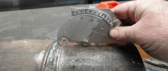
VIC – visual measurement control
VIC refers to an optical type of control and usually includes 2 stages. The first stage is visual inspection, which identifies surface defects. At the 2nd stage - it is called measuring, defects are measured and a conclusion is made about the suitability of the connection.
Visual inspection is carried out using optical instruments such as a mirror, magnifying glass, microscope, etc. or without them, by simple inspection.
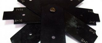
At the measuring stage, tools such as a ruler, universal welder templates (UShS2, USSh3, etc.), calipers and others are used.
VIC is a primary control; it is carried out before performing other types of non-destructive testing, since this method is very simple. It reveals surface defects, in the presence of which there is no point in carrying out other inspection methods.
Using visual measuring control, carries out incoming inspection of materials and parts. It is carried out after welding and assembly work has been completed. With its help, you can control the quality of materials and parts that have already been in operation for some time and need to evaluate their condition, as well as quality control of welded joints of metal structures, gas pipelines, pressure equipment, etc.
As already mentioned, with the help of VIC, surface (external) defects are detected. These include:
- Cracks of various origins (surface, crater, hot and cold).
- Weld undercuts.
- Violation of the geometry of the seam (deviation in height, width, displacement from the axis of the joint (curvilinearity), fractures, etc.).
- Burns and fistulas (through and non-through holes).
- Incorporation of slag (weld slagging).
- Lack of penetration (a defect in the form of non-fusion of the base metal with the filler metal) and lack of fusion of the edges.
- Pores (extending to the surface of the product)
- Surface defects that are not related to welding (nicks, surface defects of coatings: paint, galvanic, etc.)
From the listed list of defects it is clear that visual measurement control has a very wide scope of application.
If we talk about the control of welded joints using the VIC method, then the primary control is carried out by the welder himself, after completing and cleaning the seam. If the connection is responsible, then the control will be carried out by both the welder, the foreman (foreman) and the flaw detector.
Verification methods
Quality control of welding work performed in production can be destructive or non-destructive. The first methods are used selectively. One or more products from a large batch, or part of a metal product in a building structure, is checked.
It is tested on various parameters using a specific test report. But mainly they use special devices or materials to check the quality of welded joints without destroying the structure.
The main methods of non-destructive welding quality control are:
- visual;
- capillary;
- permeability test;
- radiation;
- magnetic;
- ultrasonic.
There are other methods and types of welding quality control, but due to their specificity they have not become widespread.
Checking the condition of welds is not a one-time act, it is the resulting stage that shows how the quality control system at the enterprise works.
To minimize defects in welding joints, operational control of the work is carried out. Certification is carried out regularly, at which the commission first gives permission to weld the control joint. When welders pass this test, their theoretical knowledge is tested.
Before starting work, the welder’s qualifications are checked; he must have a certificate for the right to weld certain grades of steel and a work permit.
A welding engineer and a controller from the technical control service check the quality of assembly, the condition of the edges, the performance of the welding machine, and controls the heating temperature, if this is provided for in the regulatory and technical documentation.
Quality control of welding materials is carried out from the moment they arrive at the enterprise and before use at the welding station. The electrodes are checked at each stage of storage and use, and if necessary, they are calcined.
During the actual work, check what welding mode is used: arc welding, argon arc or another type of welding. Check the order of sutures, the dimensions of the layers and the entire connection.
If special requirements are provided for in the design and technical documentation, then their implementation. Upon completion of welding, checks for the presence of the welder’s mark.
PVK – capillary method
This type is used when it is necessary to check the quality of welds for defects that are not visible due to their small size. Penetrant control is performed using special penetrating compounds—penetrants. These substances have high fluidity and fill small defects allowing them to be identified.
This method is used to check welds and critical products after manufacturing (for example, a live steam manifold) during incoming inspection, and I also check operating equipment during operation.
The process is quite simple and is therefore often used in contrast to similar magnetic control. Let's consider the control process itself.
Initially, the surface that needs to be checked is cleaned to a metallic shine with a cord brush or sandpaper so that the surface does not have too much roughness (not higher than Ra 3.2).
Next, you can treat the surface with the cleaner that comes with the penetrants. The penetrant set consists of three cans similar to cans of paint. One of them is a cleaner, the second is the penetrant itself, and the third is a developer.
After applying the cleaner, remove it with a rag and apply penetrant to the dry surface. After this, the time necessary for the penetrant to penetrate is maintained. The time may vary depending on the temperature and manufacturer, but on average it is 10-15 minutes.
After which the penetrant is washed off from the surface. At this stage, you do not need to rub the surface too hard so as not to wash off the penetrant from the defect cavity.
Now the surfaces need to be wiped with a rag, this must be done delicately so that I can remove the penetrant from the defects.
Next, a thin layer of developer is applied to the already dry surface. The developer is applied in a thin layer from a distance of 200-300 mm (distance for a spray can). This is followed by drying, which takes from 10 to 20 minutes. Drying occurs due to the natural evaporation of the developer liquid. If you need to speed up the process, you can use a stream of warm air (heat it with a hair dryer).
After drying, the surface is inspected; there should be no red spots on the surface, which will certainly appear if the products have defects.
After completing the inspection, clean the product from the developer by wiping the surface with a dry cloth.
Bottom line
Inspection methods are necessary to inspect seams produced using welding equipment. Depending on the requirements for products, testing options may vary.
For parts that do not require great resistance to mechanical and plastic loads, only a visual inspection may be sufficient. While large enterprises often require additional checks using mechanical tests and radiation methods.
PVT – tightness control
In cases where the task is to check welds for leaks, a type of control such as PVT is used. It includes many different techniques; within the framework of the article, we will consider only the main, most common of them.
The main methods of HTP are:
- Gauge – measures the pressure drop over time.
- Gas analytical - Measurement is made by the amount of freon present in the air in the control zone.
- Chemical - using ammonia or ammonium.
- Acoustic.
- Capillary – the control process is carried out based on the presence of penetrating substances in the control zone.
- Pouring water under pressure.
- By pouring without pressure.
- Bubble method (pneumatic and pneumohydraulic), as well as using vacuum chambers.
Let us dwell in more detail on the capillary and bubble processes since they are the most common and applicable in field conditions. They control through defects in both open and closed structures (when welding tanks, pipelines and many other products).
The capillary method includes methods such as:
- luminescent color;
- luminescent;
- luminescent-hydraulic;
- wetting the surface with kerosene (kerosene-chalk test)
The first 2 methods are used in cases where the structures being tested operate with a medium such as gas. Luminescent-hydraulic and kerosene-chalk test is used when the structure will work with liquids. Based on the name of the methods, it can be understood that in order to carry out control, the first 2 methods use luminescent substances with high penetrating ability, the presence of traces of which is examined under ultraviolet light on the back side of the structure being tested.
Hydraulic method
Hydraulic methods for monitoring welds, as mentioned earlier, include testing by pouring water under pressure and without it, and by pouring a stream of water also under pressure and without it.
To use hydraulic methods in cases where structures are large, their rigidity must be ensured. In cases where control is carried out by spraying, the sensitivity of control increases when using luminescent indicators.
Useful article – Tig welding what is it
Pneumatic control
Quality control by pneumatic methods of welded joints (bubble method) is carried out by filling a closed structure (reservoir, container, etc.) with air to the test pressure (1.1-1.5 of the working pressure). A foaming compound is applied to the controlled side. after which the surface is inspected for the presence of inflating bubbles. This method is also used at service stations to find a tire puncture.
There is also a method of blowing with a stream of compressed air, in which large-sized structures are controlled.
Kerosene test
When using such a method of quality control of welding work as wetting with kerosene, you can quickly and accurately identify leaks.
The process works as follows:
- Before performing, it is necessary to clean the surfaces on both sides. When cleaning, it is necessary to remove loose rust, as well as various contaminants.
- One side is pre-treated with a water-chalk emulsion and allowed to dry.
- The other side of the controlled surface is treated with kerosene.
- The time usually lasts from 1 to 3 hours.
- Inspect the chalk surface; there should be no kerosene stains on it.
Checking with a helium leak detector
Testing with a mass spectrometric or helium leak detector is a rather complex and expensive method, which is used to control the quality of welded joints of critical structures.
The control process consists of the following sequence:
- The welding seam or inspection points are cleaned of dirt and rust;
- Helium (in rare cases, the inert gas argon) is supplied from one side of the controlled structure, which in turn penetrates through welding defects in the form of a leak;
- the product may not be blown with gas, but filled completely with it if it is sealed (depending on this, different connection schemes will be used).
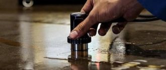
Vacuum method
The most commonly used control method in practice is vacuum (using vacuum chamber frames). This is a fairly cheap and quick way to check the quality of the weld.
The algorithm for its implementation is as follows:
- cleaning and degreasing the controlled surface (cleaning at least 150–200 mm from the weld in both directions).
- Applying a soap emulsion (foaming composition) to the controlled surface.
- Installing a vacuum chamber on the weld.
- Pumping out air and creating a vacuum in the chamber.
- Inspect the weld through the transparent camera screen for the presence of inflating bubbles, which will indicate a defect.
- Fixing defects, removing the vacuum chamber and removing emulsion residues.
This may be useful to you - How to brew cast iron
Checking welded joints for permeability
If welding is used in the manufacture of tanks, tightness control is required. To do this, tests for tightness of connections are carried out. Quality control is carried out using gases or liquids.
The essence of the method is based on creating a large pressure difference between the outer and inner areas of the container. With through-hole flaws in the weld, liquid or gas will flow from an area of high pressure to an area of low pressure.
Depending on the substance used and the method of obtaining excess pressure, permeability control is carried out by pneumatics, hydraulics or vacuum.
Pneumatic method
The use of a pneumatic welding quality control method requires pumping the tank with some gas to a pressure of 150% of the nominal pressure.
Then all welds are moistened with soapy water. Bubbles form in places of leakage, which is very easy to fix. For better visualization, an ammonia additive is used, and the seam is covered with a bandage soaked in phenolphthalein. Red spots appear in areas of leakage.
If it is not possible to pump up the container, then use the blowing method. On one side the seam is blown under a pressure of at least 2.5 atmospheres, and on the other it is coated with a soap solution. If there is a defect, it will appear in the form of bubbles.
Hydraulic method
With the hydraulic method of welding quality control, the container being tested is filled with water or oil. An excess pressure is created in the vessel, which is one and a half times more than the nominal pressure.
Then, for a certain time, usually 10 minutes, the area around the seam is tapped with a hammer with a rounded head. If there is a through welding defect, a leak will appear. If the excess pressure is small, then the holding time of the tank is increased to several hours.
MK – magnetic control
Magnetic testing is used to check the quality of welds, as well as equipment in operation to identify surface and subsurface defects that are invisible or difficult to see.
Magnetic control is divided into such methods as:
- Hall effect method.
- Magnetic particle method.
- Magnetic flux probe method.
- Method based on metal magnetic memory.
All magnetic testing methods are based on magnetic field dissipation by defects. When a test object is magnetized, a magnetic flux flows through it. If a defect (discontinuity) is encountered along the path of the magnetic flux, a stray field appears. By the shape of which you can determine the depth of the defect, its size and shape.
Magnetic control has a number of advantages such as:
- Ease of implementation;
- high sensitivity to defect detection;
- the method is highly productive;
- low price;
- the control results are visually visible;
- Possibility of application on products with different configurations;
- automation of the control process is possible.
Disadvantages of MK:
- the feature only works with ferromagnetic materials;
- high labor intensity in the control process.
Magnetic particle
The magnetic particle method is the most common magnetic testing method. To fix defects in the process of checking welding seams, ferromagnetic powder, magnetic suspension or magnetic paste is used.
Powders used for this method can be luminescent, colored, or black.
Before testing, the surface must be cleaned, removing rust, traces of paint, scale, etc.
After cleaning, the stage of magnetizing the product and applying emulsion or magnetic powder to it is performed.
Magnetization can be done in 2 ways:
- Attached field
- Residual magnetization
When monitoring in the case of using method 1, the application of the emulsion (powder) occurs at the moment of magnetization.
In the case of using a method with residual magnetization, the magnetization of the test object is carried out initially. Control is carried out after turning off the magnetizing field.
When magnetizing, the following types of current are used:
- constant;
- alternating single and three-phase;
- pulse
Magnetographic
Magnets graphic method is most often used to control the quality of welded joints on pipelines. The essence of the method is that with the help of a special flaw detector, the weld is magnetized while simultaneously recording the magnetic field on a special tape.
Fluxgate method
This method is not often used in practice.
Testing of welded joints is carried out by moving a special transducer over the surface, which has been previously prepared and magnetized. During the inspection process, signals from defects are displayed on the screen of the flaw detector, which are compared with reference values adjusted on the samples. The data obtained is analyzed and a conclusion is made about the quality.
This method includes the following steps:
- preparatory (cleaning and surface preparation).
- carrying out magnetization of the controlled product.
- scanning and signal analysis.
- demagnetization
Useful article - Do you know what Poxipol glue is used for? If not, follow the link to our article.
Hall effect method
This method is most often used in cases where products operate at high temperatures or in an aggressive environment. The Hall method provides non-contact magnetic field measurement. To use this method, no special surface preparation or control equipment is required.
The controlled products are magnetized after testing with a flaw detector with a Hall sensor. The data, as in the case of the fluxgate method, is compared with reference values.
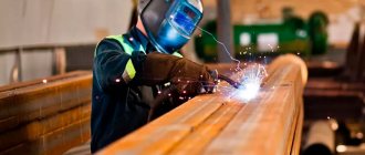
Visual inspection
Any quality check of welds begins with visual inspection. All 100% of welded joints are inspected. First, check the geometry and shape of the seam.
Visual inspection helps to identify, along with external ones, some internal defects. Thus, seam beads of variable dimensions and uneven folds indicate lack of fusion that occurs due to frequent breaks in the electric arc.
Before starting work, remove slag, scale and other contaminants from welded joints. To better see the defects, the seams are treated with nitric acid (10%). This gives the seam a matte finish, making it easier to find flaws.
After acid treatment, it is necessary to thoroughly wipe with alcohol to prevent its harmful effect on the alloy.
To improve the quality of the inspection, you can use a flashlight and an optical magnifier. To control geometric dimensions, calipers and templates are used.
Ultrasonic (UK)
This method is widely used to control the quality of welded joints. As the name suggests, ultrasound is used for testing - a sound wave with a frequency above 20 kHz (for testing it is used from 200 kHz to 100 MHz). Ultrasound propagates throughout the product in the form of waves that have physical parameters such as:
- wavelength;
- period
- frequency
There are a very large number of ultrasonic (acoustic) testing methods.
Within the framework of the article, we will not dwell on each in detail, but will consider the most common method that is used in practice when inspecting welded joints - the ECM method.
Also very important parameters are the types of waves used.
Waves are of the following types:
- Transverse (shear waves).
- Longitudinal (compression waves).
- Surface (Rayleigh).
- Lamb waves.
- Porchhammer waves.
Ultrasonic testing - control
The principle of using ultrasonic testing is as follows: with the help of a flaw detector, ultrasonic vibrations are created and introduced into the product. Ultrasound, spreading in the product and reaching the defect, is reflected from it. If there are no defects, then the sound wave is reflected from the bottom surface. Depending on the return time and signal amplitude, it is possible to determine the depth of the defect and estimate (compare with acceptable) its dimensions.
Preliminary adjustment of the flaw detector is carried out using reference samples (so-called SOPs - standard samples of the enterprise), on which the maximum permissible defect is artificially created. If during the inspection process a signal greater than the one that was configured on the SOP is detected, then the products are considered defective.
The following equipment is required for ultrasonic testing:
- flaw detector
- Lemo cable
- piezoelectric transducer (PET)
PEPs differ in:
- input - inclined and straight;
- by structure (design) - combined and separated-combined;
- by type of contact with the surface - non-contact and contact.
Inclined probes are used when you need to look for defects that are not parallel to the surface being tested.
Combined probes use one piezoelectric element that both generates and receives signals.
For separate-combined ones, 2 different piezoelements are used, one of which generates a signal, and the other receives it. In this case, the control accuracy increases.
UT – ultrasonic thickness measurement
Ultrasonic thickness gauging is used to determine the thickness of a part with access from one side. It is often used when assessing the residual life, when it is necessary to measure the wall thickness and the amount of wear.
In ultrasonic testing, a separate-combined probe is used, which is connected by a cable to a special device—a thickness gauge. To carry out UT, it is necessary to establish the speed of sound propagation in the material being measured. The adjustment is made on samples with a known thickness made of the same material that will be tested.
The testing process itself is similar to the ultrasonic testing process, only in this case the transducer is not moved, but is simply pressed against the surface at individual measurement points and rotated by 10-15 degrees.
Useful article – Welding lessons for beginners
Capillary method
This control method uses the property of liquid to be drawn into very small capillaries. The speed and degree of penetration into the material is related to its wettability and the diameter of the capillaries. The alloy is more wetted and the capillaries are thinner - the liquid penetrates deeper.
The capillary method of weld quality control allows you to deal not only with any metals, but also with ceramics, plastic, and glass. Its main use is associated with the manifestation of external flaws that are impossible or difficult to detect with the naked eye. Sometimes, using, for example, kerosene, you can detect through defects.
The method is very simple, it has been working since the need to check welding seams arose. A special GOST 18442-80 has even been developed for it.
In the capillary welding quality control method, penetrants are used - substances that have low surface tension and strong color contrast.
By penetrating into defective areas and highlighting them, penetrants visualize welding flaws. They are made from water, kerosene, transformer oil and other liquids.
The most sensitive penetrants can show defects as small as 0.1 microns in diameter. The capillary welding quality control method is effective for defects up to 0.5 mm wide. It does not work for large pore diameters or cracks.
The method using penetrants involves cleaning the surface, applying a control liquid and revealing flaws. A very effective way to control welded joints is using kerosene.
Despite the variety of welding quality control devices, testing by this method is still used. A chalk solution is applied on one side, time is allowed to dry, then the seam on the other side is lubricated with kerosene. Defective areas appear after a few hours in the form of dark spots.
Radiation control
Radiation monitoring (RM) is used for the most critical facilities, where high demands are placed on the quality of welding. The number of joints (% of inspection) that must be inspected by x-ray is determined by the regulatory documents for the object of inspection. For process pipelines, for example, such a document is GOST 32569.
Most often, the following methods are used for radiation monitoring:
- Radiographic
- Gammagraphic
The radiographic method uses an X-ray machine, which is located on one side of the controlled object, and a film (also known as a detector) is installed on the other.
During operation, the device produces radiation (X-rays), which passes through the metal and forms an image on the film. The image can be viewed only after processing in chemical reagents and subsequent drying.
X-ray machines are divided into 2 types:
- Pulse.
- With constant potential.
Pulse ones are cheaper, have less weight and dimensions. Typically used for thin products and small pipe diameters. Since the radiation from such devices (integral dose) is low.
Devices with a constant potential are more accurately adjusted and are most often used for thick-walled structures. Compared to pulse devices, such devices are heavier and larger, and their maintenance is much more expensive.
The gammagraphic method assumes that instead of an X-ray machine (radiation generator), a gamma radiation source will be used containing radioactive elements such as: Iridium - 192; Selenium – 75; Cesium - 137 and so on. Using this method, a product with a wall thickness of up to 300–400 mm can be illuminated.
Gamma sources are used only for thicknesses over 50 mm, since smaller thicknesses do not create sufficient resistance and the image is of low clarity. These devices are a closed, impenetrable container containing a hermetically sealed ampoule containing a radioactive isotope.
Radiation method
There are a couple of variations of this seam control technique:
- using gamma radiation;
- using X-rays.
The simplest solution is to check the workpiece with x-ray . This technology allows you to penetrate metal products, reflecting information on photographic film. In the resulting image you can see certain internal defects. Penetrating radiation makes it possible to detect edge displacement, gas pores, slag inclusions and other defects.
Gamma rays operate on a similar principle, but have the following advantages:
- isotopes do not lose their efficiency for a long time;
- the ability to study complex structures;
- increased radiation permeability;
- simpler and more compact equipment.
Remember that these radiations are very dangerous for the human body. Therefore, experienced specialists in protective equipment are allowed to perform such work. The workplace is also protected. For this purpose, screens, lead plates and other means are used.
Acoustic emission
The acoustic emission testing method provides excellent results for detecting defects at an early stage. This method, together with other non-destructive testing methods, provides comprehensive data.
It is based on recording signals arising from structural and structural changes. In simple terms, this method monitors any changes in the structure due to sensors attached to the structure or equipment. That is, when defects occur (corrosion, cracks, delaminations, etc.), sensors record this and convert it into an electrical signal. The signal is processed through a multi-channel system and converted into data, which is directly processed and determines the location of the defect.
In this way, it is possible to track changes in the state of structures and equipment, but it is impossible to accurately determine the parameters of the detected defect. This method is best used in conjunction with ultrasonic or radiographic testing methods.
Welds: concept, education, structure
Welds
- these are, in fact, the combined edges of adjacent elements, transformed under the influence of a welding machine into a single one-piece structure. They are the result of crystallization of the molten material, its plastic deformation under high pressure, or a combination of these processes.
Structural welds
consist of base and filler metals (polymers, composites), which are mixed during the welding process and form a more or less homogeneous substance - an alloy.
They directly border on a narrow fusion zone containing crystallized particles of both materials, and then on a heat-affected zone. The latter is actually a base metal, which, with a change in temperature, slightly changed its structure and properties, but completely retained its chemical composition. Visually, the thermally affected zone is determined by the lightest shade. The darkest color indicates the location of the seam
.
Structure of welded joints
is also considered from the point of view of geometry. In cross section, they form structures from the following elements:
root seam
;
· penetration (melting);
seam thickness
;
· front surface;
· boundaries of the outer surface;
· gain.
In butt joints
The penetration of the root also differs; in corners, the
weld
.
That is, in addition to the main elements,
additional elements may be present
welding seams Their presence depends entirely on the type of connection
, and the parameters are regulated
by GOST
2601–84.
Eddy current testing
Eddy current testing is widely used in the aviation and nuclear industries, as well as in the production of rolled metal, castings and bearings. This method is good at identifying surface and subsurface defects. It can be used to measure the thickness of a coating or individual layers of material. The method is perfectly mechanized and automated. To perform it, there is no need to contact the surface and does not require a coupling liquid, unlike ultrasonic testing.
The method is based on changing the resistance and voltage in coils (eddy current transducers).
Ultrasound technique
Flaw detection using ultrasound makes it possible to identify certain deviations that are formed during the reflection of ultrasonic waves from the boundaries of media having different properties. In simple terms, a special device sends out a signal that is reflected after reaching the material. If any defect is encountered along its path, it is reflected in the integrity of the wave, which is what the equipment is trying to capture. Different defects have different signals, so identifying the origin and nature of the defect will not be difficult. This technology allows you to identify both external and internal defects.
Destructive testing methods for welded joints
Destructive testing, as is already clear from the name, assumes that the controlled product will be destroyed.
It is carried out on specially welded samples using the same technology that will later be used on working products.
Let us list the main methods of destructive testing most commonly used in practice:
- Mechanical testing of welded joints.
- Dynamic testing of welds.
- Hardness measurement.
- Metallography.
- Stillscoping.
- Product hardness measurement.
You can find a complete list of all test methods by downloading it from the link here.
Mechanical static tests
This type of testing is carried out for welded joints of critical structures. Its essence lies in the fact that during testing the sample is either gradually loaded with a slight increase in load, or one-time without an increase.
The methods include the following tests:
- Compression;
- stretching;
- bend;
- twisting, etc.
Mechanical dynamic tests
Unlike static tests, during dynamic tests the sample is loaded with shock with a duration of impact on it of no more than hundredths of a second.
Dynamic tests include:
- Impact bending test at elevated temperatures;
- impact bending at low temperatures;
- impact bending at room temperature;
- impact test.
Hardness measurements
The hardness of welded joints is most often measured using the following methods: Brinell, Rockwell, Shore or Liebou.
The most commonly used method on objects is the Liebue method, which is based on changing the speed of a ball bouncing off the surface of the part during measurement.
The Brinell, Rockwell and Shore methods determine hardness by pressing a diamond prism, metal ball or steel needle into the surface of the test product, assessing the force and depth of pressing.
Paperwork
The results of diagnostic operations are recorded in the appropriate report or conclusion drawn up by an expert. The document reflects the content of all defects and provides a detailed description of the violations committed. The form of the act or conclusion must comply with the requirements of the regulations. Also, the team of flaw detectors notes the inspection results in the welding log, the need for maintaining which is established by law for each facility.
The completed entries in the report and journal are accompanied by detailed diagrams containing a sketch of the controlled connection with the defects noted. This allows violations to be identified for subsequent elimination.
During the inspection process, a corresponding chalk mark is made directly on the product next to each defect.
Based on the results of inspection of welds and acceptance of the object, a set of documents is formed. In addition to the act and journal, this includes certificates for the materials and equipment used, electrodes, copies of certificates of welders, experts who conducted a study of the quality of the welding performed. Such documents are not just a formality. Properly executed papers are carefully examined by representatives of state regulatory authorities when accepting facilities for operation and in the event of a possible subsequent accident at the accepted facility. This allows us to establish the causes of the emergency and punish those responsible.
Careful quality control of welding and welded joints is especially important in the manufacture of critical metal structures, elements of lifting cranes, vessels and pipelines operating under pressure, and other high-risk equipment. Therefore, the further safety of operation of production and construction facilities largely depends on the qualifications and attentiveness of experts.
Capillary technique
This method is based on certain properties of liquids that have low surface tension values. These liquids do not collect in separate drops, but are constantly in a fluid state, filling holes and small grooves. This way you can identify surface flaws.
In this case, a special composition is applied to the welding joint, instantly filling the defects. After this, the seam is thoroughly inspected. For convenience when working, dye is added to the liquid.
Magnetographic control
1 - ferromagnetic film;
2 - electromagnet; 3 - direct current source; 4 - crack in welding; pulses: 5 - cracks, 6 - lack of penetration, 7 - networks of pores Magnetographic testing is nothing more than magnetic flaw detection. This method allows you to detect the so-called stray fields. They are detected when defective areas are magnetized and are reflected on the radiogram in the form of graphs.
If the seam is made with high quality and the metal is fused evenly throughout its thickness, then the magnetic lines are distributed evenly in it without bending. If there are various defects in the seam, they will spread chaotically. The field is deflected and as a result of this, so-called stray fields are formed.
This method is used when performing quality control of semi-automatic welding in a submerged arc or in an inert environment. The metal thickness should be in the range from 2 to 25 mm. The magnetographic method allows you to identify the following defects:
- longitudinal microcracks;
- lack of penetration;
- chains and accumulations of slag;
- gas pores.
All of the above has a significant impact on the strength of the connection and can cause fatal failure. The control procedure using magnetography is carried out in two stages:
First, the product is magnetized with a special device. At this stage, the magnetization fields are recorded on magnetic tape.
At the second stage, information is read from the tape. For this purpose, flaw detectors are used.
Ultrasonic flaw detector Smartor
To perform magnetization, movable and stationary magnetizing devices are used. Stationary ones affect the seam from both sides, outside and inside. Movable magnetizers of the PNU type are most often used. In the process of working, they create a homogeneous flow enclosed between two poles.
The poles are connected by a core to create a half circuit of magnetic flux. The second part of the core is the weld. A magnetizing coil is placed on the core. The magnetization apparatus moves on special non-magnetic wheels. The distance between the controlled joint surface and the poles plays an important role.
Movable magnetizing devices are used to control welded joints of small and medium-sized pipes with a diameter of 100 to 1020 mm. The wall thickness should not be more than 16 mm. If it is necessary to control the quality of a welded joint on a smaller pipe, then magnetizing pliers or forks should be used.
To carry out quality control of the welded joint of pipes of larger diameter in the range from 1220 to 1420 mm, a device that has stepwise movement is used. This device is called MUN-1. It allows you to control joints made of metal up to 20 mm thick. It is equipped with a remote control, thanks to which the process is controlled and the device is controlled. To control the quality of joints of different diameters in this range, special replaceable shoes are used.
To carry out quality checks, construction organizations contact the construction control center
If you need to check the connection of pipes with a diameter of 1420 mm and a wall up to 25 mm, then you must use a UMD-142 type installation. It is mounted on special mechanized welding bases. If it is necessary to carry out quality control of welding of pipeline joints on the route, then the LPM-K mobile laboratory is used for these purposes. A ring magnet is used as a magnetizing device. It allows you to completely cover the entire joint surface.
The operation of the magnetizing device used in the inspection of large pipe joints requires a powerful power source. Mobile stations of the SPP-1 and SPA-1 types are used. It is also possible to use welding machines, but in this case it is necessary to use a rheostat. To record data, previously a tape 35-70 mm wide on a triacetate or lavsan base of types MK-1 and MK-2 was used. It was stretched by motors over the magnetized area. The device had a beam tube on which single magnetization pulses were reflected.
MD-30G, MD-11G, MGK-1 and MDU-2U were used as means of visual display of information.
Flaw detection of welded pipe joints on gas and oil pipelines
Cracks
Defects refer to discontinuities and are local breaks in the weld or HAZ metal, as well as in the base metal. Cracks are considered unacceptable defects because they act as stress concentrators and reduce the strength of the welded joint. They appear for the following reasons:
- Incorrect grade of filler metal and/or flux. It is quite difficult to make a mistake with conventional quality structural steels. But tool and stainless alloys require a careful approach to the selection of wire and piece electrodes.
- Temperature violations. These include overheating of the HAZ, high cooling rates, and lack of heat treatment to relieve residual stresses.
- Hydrogen dissolved in a metal. The main reason for this phenomenon is moisture contained in poorly dried flux or electrode coating.
- Incorrect connection assembly. Rigid fastening of parts leads to the formation of cracks during cooling of the structure after welding.
Lack of fusion and lack of penetration
Failure of fusion is the failure of the connection between the base and filler metals or between individual weld beads. This discontinuity significantly reduces the strength of the connection and makes it unsuitable for use. Lack of penetration is an insufficient depth of penetration of the base metal. Lack of fusion and lack of penetration are often accompanied by pores and slag inclusions.
One of the main reasons for the occurrence of such defects is exceeding the optimal welding speed, when the weld pool does not receive enough thermal energy to melt the base metal. Lack of penetration and failure of fusion can be caused by other reasons, for example:
- improper cutting of edges;
- assembly with small gaps;
- poor quality cleaning of workpieces from rust and traces of oils;
- displacement of the electrode away from the weld axis;
- welding at low current values;
- insufficient heating of workpieces before welding (on semi-automatic machines under a layer of flux).
Foreign inclusions
Solid inclusions (single, linear or clusters) often get into the weld metal, the size of which can reach several millimeters. Like other defects, solid inclusions have a negative impact on the strength of the joint and are stress concentrators. According to the composition they are distinguished:
- Slag inclusions . They are formed if the slag formed during melting of the flux or coating does not have time to float to the surface of the weld pool and remains in the metal. One of the most likely reasons for the formation of slag inclusions is the use of thin-coated electrodes. An insufficient amount of slag leads to rapid cooling of the bath and crystallization of the weld. The formation of inclusions can also be caused by insufficient current, incorrect tilt of the electrode, or poor removal of slag when welding in several layers.
- Flux inclusions . Flux can remain in the metal if it has not had time to react and turn into slag. The main reason is an incorrectly selected particle size distribution.
- Tungsten inclusions . They appear during argon arc welding with a non-consumable electrode. Tungsten metal rarely gets into the melt. It is most often found in the form of oxides and carbides. The reasons for their entry are most often incorrect sharpening of the electrode and the presence of deposits on its surface. Tungsten metal can get into the weld when it comes into contact with molten filler metal.
- Oxide films and inclusions . Their presence indicates insufficient protection of the weld pool from atmospheric oxygen.
Most often, foreign inclusions are located inside the metal and do not come to the surface, so to detect them, welded joints are inspected using non-destructive methods.
Gas cavities
This group of defects includes closed and superficial pores, cavities, fistulas and craters. The presence of such defects is unacceptable in vessels operating under pressure and vacuum, in pipelines and containers for storing liquid and gaseous products. For other metal structures their presence may be acceptable. But each case must be analyzed individually in relation to operating conditions.
Pores and cavities are the result of the accumulation of gases in the weld metal, which do not have time to escape before it crystallizes. The longer the bath is in a liquid state, the lower the residual porosity of the joint, all other things being equal. Among the most likely causes of pore formation are:
- the presence of contamination on the surfaces being welded, wire, electrodes;
- high welding speed;
- increased humidity of the flux and electrode coating;
- drafts or air leaks through the gap between the parts being welded (when welding in protective gaseous environments);
- incorrect polarity;
- long arc welding (welder error).
When examining welds, the cause of pore formation is determined depending on the nature, size and location of the defect.
A fistula is a cavity in the form of a channel or tube. They are formed in places where gas escapes to the surface of the weld and have different lengths, diameters and spatial orientations. The reasons for their formation are sticking of the electrode, sudden break of the welding arc. Most often they occur when welding in vertical or overhead spatial positions.
In places where the arc breaks, craters and shrinkage cavities can also appear. The most common reasons for this phenomenon are errors in the actions of the welder: working at high currents, too large a volume of the weld pool.
Deviations in the geometry of metal structures
Warping makes it difficult to assemble equipment that includes welded parts and metal structures. To compensate for changes in their geometry, it is necessary to use workpieces with increased allowances for subsequent processing. Structures made of thin sheets and austenitic stainless steels exhibit the greatest tendency to deformation.
The participation of the welding laboratory in the development of technology allows us to reduce warping to an acceptable level. The most effective measures to reduce deformations are:
- increasing welding speed;
- double-sided welding with symmetrical groove (reverse deformation method);
- blowing, the use of copper pads to increase the rate of heat removal;
- welding in separate sections with intermediate cooling.
A complete classification of defects in welded joints is presented in the GOST R ISO 6520-1-2012 standard (Part 1).
Price list
| Name of work/type of tests | Unit measurements | Price RUR, excluding VAT |
| Visual and measuring control of welded joints of reinforcement – longitudinal seams | 1 node | 200 rub. |
| Visual and measuring control of welded joints of reinforcement – butt joints of any diameter | 1 node | 100 rub. |
| Visual and measuring control of welded joints of sheet metal structures | 1 p.m. | 100 rub. |
| Visual and measuring control of welded joints of pipelines with a diameter | ||
| up to 50 mm from 50 to 100 mm from 100 to 300 mm from 300 mm to 600 mm from 600 mm to 800 mm from 800 mm to 1200 mm from 1200 mm to 1500 mm | 1 joint | 50 rub. 100 rub. 200 rub. 350 rub. 450 rub. 500 rub. 550 rub. |
| Ultrasonic testing of welded joints of pipelines with diameter | ||
| up to 50 mm from 50 to 100 mm from 100 to 300 mm from 300 mm to 600 mm from 600 mm to 800 mm from 800 mm to 1200 mm from 1200 mm to 1500 mm | 1 joint | 200 rub. 350 rub. 750 rub. 1300 rub. 1500 rub. 1700 rub. 2000 rub. |
| Ultrasonic testing of welded joints of sheet metal structures (thickness up to 20 mm) | 1 p.m. | 700 rub |
| Ultrasonic testing of welded joints of sheet metal structures (thickness 21-30 mm) | 1 p.m. | 1000 rub. |
| Ultrasonic testing of welded joints of sheet metal structures (thickness 31-40 mm) | 1 p.m. | 1200 rub. |