Home / Articles
Jigs for drilling holes greatly facilitate the task of assembling and manufacturing furniture and very accurately create the necessary holes in the material. This is achieved by fixing the drill. Bushings are included to assist the jig. This allows you to connect the elements as firmly and quickly as possible, secure them and increases the durability of the final product. What distinguishes them from standard templates is the ability to guide and fix drills at a certain angle.
Double-column climbing conductors with pneumatic clamp
Designed for drilling workpieces of various shapes. Replaceable adjustments are installed on fingers 1 (cylindrical and cut), a plate with conductor bushings is installed on the upper fingers 2 .
The workpiece is clamped by lowering the top cover 3 connected to the rod 4 of the pneumatic actuator located in the lower part of the housing. 5 is used for control . Rod stroke ~ 8 mm.
The force on the rod with an internal diameter of the pneumatic chamber of 140 mm and air pressure in the network piz = 4 kgf/cm2 is ~450 kgf.
Dimensions in mm
| A | IN | N | H1 | h | h1 | C | C1 | D | D (add. off according to C) | L | |
| min | max | ||||||||||
| 70 | 90 | 50 | 80 | 160 | 12 | 6 | 125 | 38 | 210 | 13 | 280 |
| 100 | 120 | 80 | 120 | 205 | 15 | 8 | 180 | 53 | 270 | 16 | 350 |
Up
What is a conductor in construction?
When installing steel and reinforced concrete structures, devices are used that make it possible to temporarily hold the element installed in place and adjust its position when aligning and bringing it into the design position.
Single devices are designed to hold one element, group devices - one element or several. Sets of such devices are called mounting equipment.
Mainly two types of mounting equipment are used. The first type ensures free installation of the element and subsequent alignment with adjusting screws or other devices. The second type directly fixes the element within a given tolerance.
Braces
(see diagram below, pos. a) - flexible (made of ropes) mounting devices that work only in tension. Columns, most often metal, with a height of more than 12 m, as well as other structures, for example the first truss mounted in the span, are temporarily secured with braces. Braces 3 are secured to previously installed columns or foundations, if permitted by the work design, or to inventory anchors. To align the columns, the braces are equipped with screw ties 4, which give the braces the necessary tension.
Columns are temporarily secured directly in the foundation shell with wedges
or
wedge liners
5, allowing the bottom of the column to be moved in the foundation shell 1.
Struts
– rigid mounting devices that operate in compression and tension are designed to hold structural elements in a given position.
Struts (see diagram below, item b) are the most versatile and widely used devices for temporary fastening and alignment of wall panels, partitions, columns up to 12 m high. The struts have a telescopic design, which allows them to change their length. They are equipped with towbars, gripping locks or hooks with sliding couplings 6, clamps 8. The design features of such struts and their gripping devices depend on the slinging elements of the structures. The presence of towbars in them allows you to smoothly change the length of the strut by 500 mm and, due to this, tilt the structure being adjusted in the desired direction.
Devices for temporary fastening and alignment of building structures
| a – brace, b – strut, c – jig for installing a column in the foundation glass, d – jig for installing columns on the heads of previously installed columns; 1 – foundation, 2 – column, 3 – brace, 4 – screw tie, 5 – wedge clamp, 6 – hook with sliding coupling, 7 – telescopic rod, 8 – clamp, 9 – panel, 10 – coupling bolts, 11 – frames , 12 – spacer jack, 13 – locking pin, 14 – screws for aligning the column, 15 – screws for securing the jig to the column head, 16 – rotary beam, 17 – column head. |
Read also: Esr meter on atmega8
Spacers
– a rigid linear-mounting device, usually telescopically extendable. In terms of its main structural elements, it is similar to a strut. Spacers are placed between the mounted and installed structures, for example, between adjacent trusses or partition (wall) panels. To secure them to the structure, the spacers are equipped with clamps or other gripping devices.
Connections
– linear mounting devices that do not have their own stability (work in tension), intended only for temporary fastening of mounted elements in a given position. The connections are secured to the structures with clamps.
Conductors
– universal frame devices of spatial type. They are installed on foundations or other structures and temporarily attached to them. Reinforced concrete columns are fixed in the conductors; often the conductors are used as scaffolding for the installation of crossbars and other elements of the prefabricated frame of buildings.
Single conductors
(see diagram above, item c) are used for installing reinforced concrete columns up to 12 m high in foundation cups. The conductor is assembled from two frames 11, tightened with bolts 10, the columns are moved during alignment with spacer jacks 12. Another type of single conductor, for example from L-shaped semi-frames, is an angle-shaped or one-piece from a U-shaped semi-frame (see diagram above, pos. d) with folding (rotating) beams 16, designed for installing column 1 on the heads 17 of previously mounted columns.
To accurately install many bolts in a complex foundation requires a lot of preliminary work. Usually, a special design of installation devices is developed, which must ensure the exact position of bolts or other embedded parts, prevent them from moving during concreting, be simple in design and light in weight. The latter requirement is explained by the fact that the mounting fixtures are usually poured with concrete and serve as additional reinforcement for the foundation.
Mounting devices consist of two parts - a conductor and a frame. The jig is used to place the bolts, and the frame is used to install the jigs in the required position.
In fig. 13 shows the design of the mounting fixture. 2 pillars are installed around the future foundation in such a way that formwork can be attached to them. For this purpose, the racks have welded brackets 3. The racks rest on plates 1, poured into special concrete bedside tables 6. These bedside tables are made according to the instructions of the installers simultaneously with the concrete preparation of the foundation.
Read also: Microcircuit omvk2p300 1242u bfs12ag1 and its analogues
Fig. 13. Frame arrangement for installation of foundation bolts.
The racks are connected to each other by longitudinal and transverse girders 4. The racks and girders are made of channels, angle steel or other profiles and are connected to each other by welding. When installing large objects, standard racks and purlins are developed, from which frames of any complexity are assembled.
Conductors 5 are installed on the frame beams. The conductor is a steel sheet or a frame made of corners and sheets, in which there are holes for bolts.
The foundation bolts are suspended in the jig with nuts, and the lower ends of the filler bolts are secured with wire or thin rods so that during concreting they do not accidentally move or warp. The conductor is welded to the frame by electric welding.
Pa fig. 13 shows conductors mounted on the frame with two bolts each. In complex foundations, jigs can be used for four or more bolts simultaneously. In fig. 14 shows jigs for four and twelve bolts. The diameter of the holes in the jig should be 1-2 mm larger than the diameter of the bolt.
Fig. 14. Types of conductors.
When installing bolts, it is necessary to be especially careful in marking the holes of the jigs and installing them along the axes and in height. The accuracy of the jig completely determines the accuracy of bolt installation. It is better to tinker with the jig than to correct the position of the bolts later.
As a precaution, a well 300-400 mm deep is sometimes provided at the top of the filler bolts, which may be needed to slightly correct the position of the bolt. The plugs for such wells are best made from roofing iron. To increase rigidity when rolling plugs, two rollers are rolled at their edges. In the same way, metal plugs are suspended from the conductor to form wells for embedded bolts.
In large foundations, the frames and conductors bear significant bolt weight, especially with heavy cast slabs at the lower end. To unload the frame, a stand is placed under each bolt. Racks are made from waste channels, pipes or other metal. The length of the stand should be such that it can be driven under the hanging bolt with some force and thereby unload the frame.
Read also: What is graphite lubricant for?
In fig. Figure 15 shows a view of the frame of a large foundation of a modern rolling mill. The upper part of the foundation, racks, girders from beams and jigs from channels, suspended plugs are visible.
Fig. 15. The upper part of the rolling mill foundation frame.
Although the conductors themselves and some racks are located outside the foundation, some of the mounting fixtures still remain in the concrete. This irreversible metal consumption is 15-17 kg per 1 m 3 of concrete. The desire to reduce this consumption has most recently led to the creation of precast concrete pillars, shown in Fig. 16. The racks 1 rest on concrete shoes 3, which have recesses with inclined walls. In these recesses, the racks are secured with oak or steel wedges 2. At the top, the stability of the frame is achieved by purlins 6, on which conductors 5 are placed. In addition, additional oblique braces 4 made of round iron are provided. The irreversible consumption of metal in the manufacture of such frames is only 2-3 kg per 1 m 3 of concrete.
Fig. 16. Foundation frame on prefabricated reinforced concrete racks.
Single frame structure of Mo-sorgstroy consists of two L-shaped frames, connected. each other diagonally using four pairs of tightening screws and a latch, and the section is made of four racks connected horizontally with belts. There are four rows of screws on each side of the jig. The two bottom rows serve to secure the K.s. on the head of the underlying column, the middle one is for aligning the bottom of the installed column, and the top one is for aligning it vertically. Using the same screws, you can temporarily secure the installed columns.
Construction conductor - technical. a means for temporary fixation and alignment of statically unstable structures of buildings and structures. K.s. subdivided: according to the installation site - into the foundation glasses, into the heads of lower columns protruding above the ceiling, into the heads of lower ones, located. at the floor level, on the supporting surfaces of platform joints; according to the number of columns installed by one conductor - into single (for one column) and group (for two or more columns); according to the type of assembly during installation - detachable and one-piece; auxiliary equipment devices - with lower platforms for working on the facade of a building, with upper platforms for working at heights.
Jig conductor with pneumatic clamp
Installation and securing of the workpiece is the same as in the previous jig. Pneumatic piston drive 1, together with the distribution valve, is moved to the side. Lifting and lowering of the cover 4 is carried out through the gearing of the column 3 with the roller 2 .
The clamping force at air pressure in the network piz=4 kgf/cm2 is 550 kgf.
Up
Scope of use
Furniture jigs are devices that no furniture maker can do without while working. Such devices allow you to avoid the main problem in furniture production, namely the drill entering at the wrong angle. If you make such a mistake, it is very difficult or even impossible to correct it later. Such a device not only makes it possible to correctly direct the drill during operation, but also allows the tool to constantly maintain the desired trajectory (flat, perpendicular or at an angle).
Such devices are used both in the design and production of furniture, and during assembly, when there is a need to make holes for fastening elements together. Often, for such actions, conductors are used for firmmats or dowels, without which it is impossible to make straight holes
Also, you cannot do without this device if you need to make holes at an angle or in the end of a thin slab (it is especially important to use the device when working with chipboards)
When drilling holes using this design, the process itself is quick and simple. The fastener allows you to do work at any distance from the edge of the slab, as well as regardless of its width.
In the furniture industry, dowels are often used as fasteners. But at the same time, this option has already existed for a long time, and their use requires the presence of a drilling jig when working. The only condition and at the same time a problem is the fact that the parts being connected to each other must have a right angle during operation. Therefore, such elements must be located exactly perpendicular to each other. When making holes for dowels and adding parts, it will be very difficult to do without a jig.
Furniture production is not the only area of application for such devices. They can often be used to make holes in pipes and other round-shaped parts. Special devices allow you to make high-quality holes even in the smallest tubes.
Jig with pneumatic clamp for drilling holes in cylindrical workpieces
The workpiece is mounted on prism 1 . To adjust to a given distance from the mounting end to the center of the drilling, use the adjustable stop 3 . Clamping is carried out by lowering the conductor plate 2 , connected through guide columns with a movable pneumatic cylinder 4 . 5 are used to return the plate to its original position .
- The diameter of the processed workpieces is 8-22 mm.
- The largest drilling diameter is 6 mm.
- Clamping stroke 12 mm.
- The clamping force at air pressure piz=4 kgf/cm2 is ∼160 kgf.
Up
What is it used for?
When manufacturing and assembling elements of furniture structures, specialists have to carry out many similar actions related to both marking locations and drilling future holes. The furniture jig allows you to optimize both of these processes.
According to their functional purpose, furniture jigs can be marking and drilling. The first, as their name implies, are intended to simplify the marking of the locations of future holes. Drilling jigs used in the production of furniture structures exclude the use of marking devices.
Drilling jig for confirmations
Many people purchase a furniture template, designed for preliminary marking of the locations of future holes, in a factory-made version. However, you can make a jig for assembling furniture with your own hands. The easiest way is to make a furniture jig from a metal ruler, to which the crossbar is screwed strictly perpendicularly. This furniture template is a multi-purpose marking device that is easy to make and use. The holes through which the drilling sites will be marked are made in a metal ruler at a certain distance. So, if holes are drilled for a minifix, then the distance between them will correspond to 32 mm, and for shelf holders - 100, 200 or 300 mm.
You can make a simple furniture marking template using a regular carpenter's square as a base, in which holes are also drilled at the required distance. Such a marking device, although more functional, is less stable on the surface of the workpiece. This is its most significant drawback.
The simplest furniture template for handles is a plate with calibrated holes, on the reverse side of which a stop strip is fixed
Using a similar principle, using available materials, you can make highly specialized marking devices (for example, a jig for furniture hinges or for marking holes intended for fixing furniture handles or any other furniture fittings).
Of course, if you have your own serious furniture production and the volume of assembly operations performed is quite large, you should pay attention to professional equipment for furniture assembly. However, the cost of such furniture jigs and templates, especially if they are produced under well-known brands, is quite high
Double-column conductors with mechanical clamp
Installation and securing of workpieces are similar to the previous one. The workpiece is clamped by lowering the top cover 1 using handle 2, locking in the lowered position with a cone lock.
| A | A1 | B | IN 1 | N | H1 | H2 min | WITH | C1 | C2 | d (additional deflection according to C) | |
| min | max | ||||||||||
| 75 | 170 | 120 | 155 | 60 | 90 | 40 | 145 | 75 | 125 | 38 | 13 |
| 105 | 215 | 170 | 215 | 90 | 130 | 55 | 200 | 110 | 180 | 58 | 16 |
| 140 | 120 | 240 | 290 | 125 | 175 | 70 | 265 | 150 | 250 | 70 | 20 |
| 185 | 350 | 320 | 380 | 170 | 230 | 80 | 330 | 200 | 335 | 85 | 24 |
Up
Rock jig with mechanical clamp for drilling holes in cylindrical workpieces
The workpiece is mounted on prisms 1 and 2 . Supporting prism 1 is movable. To adjust to a given distance from the mounting end to the drilling center, use stop 3 .
- The workpiece is clamped by lowering the conductor plate.
- Locking with a cone.
- Dimensions of blanks: diameter 12-30 mm.
- The shortest length is 15 mm.
Up
Portal type conductors
Replaceable adjusting devices and a plate with conductor bushings are installed on the fingers. Clamping is carried out by lowering the top cover, locking with cones. Provides reliable fastening.
Dimensions in mm
| A | B | H | H1min | l1 | C | d (additional deflection according to C) | L | L1 | ||
| min | max | |||||||||
| 160 | 130 | 60 | 100 | 218 | 170 | 95 | 140 | 16 | 230 | 310 |
| 200 | 160 | 95 | 150 | 268 | 210 | 120 | 170 | 280 | 370 | |
Up
Materials from which conductors are made
There are many conductors that are made from completely different materials. There are even plastic and glass conductors.
However, the generally accepted opinion is that the best devices are made of metal (the best option is stainless steel).
This is not surprising, because a metal drilling jig can provide a number of advantages. Mainly among them, it is worth highlighting the clearest directionality of the drill, virtually no deformation, and also the fact that metal conductors do not heat up during operation.
Jig for drilling holes in bolts, studs and shafts
Designed for drilling small (up to 5 mm in diameter) holes. Block 5 , depending on the diameter of the part, has two prismatic sockets. To install to a given length, the block can be moved along the guide grooves of the housing 4 . Pin 1 serves as a stop. Its length position is adjusted with a nut. The eccentric 2 , which clamps the part, is adjusted in height with a bolt 3 .
Up
Areas of application
Conductors, with the help of which furniture is made, are considered especially in demand.
When creating any item to firmly fix furniture boards and panels, it is very important to hit the part at the correct angle, and jigs help ensure this accuracy. Any modern furniture production cannot do without additional high-precision drilling equipment, since wood, MDF, chipboard and other types of products can be damaged during drilling
A jig for furniture dowels allows for straight drill insertion and eliminates defects.
Common use cases:
- installation of structures with mandatory perforation for fasteners and fittings - in these cases, confirmat and jig for dowels are relevant;
- drilling at a certain angle, when work is carried out with thin sheets and panels made of finishing and furniture materials such as particle board and finely dispersed wood fiber board;
- the device is in demand in the serial production of furniture - the use of templates speeds up and simplifies the production of holes, regardless of their location and size of the part.
It may seem to some that dowels, these plug-in threadless tenons or rods, are outdated fasteners, but they are still considered the most reliable fasteners in the production of various furniture designs
In addition to being used in the manufacture of furniture products, jigs are used in other industries, and with the help of this important part, perforation is possible even in pipes with a minimum internal diameter. Ease of use and versatility allow you to use these useful devices in the following areas:
- construction industry - many structures require precise execution of holes for reliable fastening;
- the area of creating various communication systems for public and home use, mainly for the installation of pipelines for various purposes;
- mechanical engineering sphere - here conductors are used for workpieces made of any materials of various dimensions.
Drilling templates come in different sizes, simple and complex in design. In some cases, it is better to buy ready-made models, but it is also possible to make simple modifications yourself. This is quite justified when the required conductor has a high price.
Stand with an overhead jig for workpieces that do not have mounting holes
The overhead jig is installed on two fingers using folding washers. The workpiece is clamped between the jig and the plate. The clamping is carried out by lowering the conductor plate, locking in the lowering position with cones.
Up
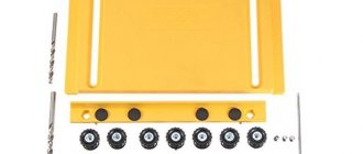
Dowel hole jig
The jig for drilling holes for dowels is one of the simplest templates in its design. However, you should know that such templates should simplify the work of the master, and not complicate it when he is forced to use complex instruments.
Dowel hole jig
Used for assembling furniture. Should allow simultaneous drilling of holes without changing the device. For manufacturing, different materials are used that have different strength characteristics. The most durable unit can be considered a steel unit.
Stands for overhead conductor with hand fastening
The workpiece can be installed directly on stand 1 or on an intermediate spacer. The overhead jig is centered along the mounting diameter dC3 of pin 2 and is held in place by a quick-release washer when fastened. The jig and the workpiece are secured simultaneously by lowering a finger connected through a helical clutch to the roller carrying the handle 3 .
Locking with a cone lock.
Dimensions in mm
| D | H | h | d (additional deactivation according to C) | d1 | b | |
| min | max | |||||
| 125 | 75 | 20 | 75 | 20 | 12 | 21 |
| 200 | 90 | 20 | 85 | 25 | 16 | 21 |
| 300 | 105 | 25 | 120 | 28 | 20 | 25 |
Up
Benefits of use
Essentially, such a jig acts as a template for making holes so that they are made as accurately as possible. They can be used for those holes whose axis is perpendicular to the surface of the workpiece, as well as for working at an angle.
This tool is an excellent alternative to sketches and manual measurements. You can place the drill strictly at the desired angle in relation to the workpiece and will not allow any deviation. The result will be especially noticeable when it comes to making deep holes.
If you use such a high-quality device for working with chipboard, then it should have the following characteristics:
- facilitate quick assembly of furniture without the need to use complex tools;
- make it possible to make several holes simultaneously without manual marking;
- significantly improve the quality of work with the drill.
Conductors are made from different materials; there are models based on plastic or organic glass. However, the best option is considered to be steel, which has such advantages as:
- minimal likelihood of deformation;
- the drill is directed as clearly as possible;
- no heating during operation.
Very often, overhead models based on lightweight materials that are easy to manipulate are used as furniture jigs. Many people use factory or homemade tools.
And the most qualified and experienced craftsmen no longer use a jig, since they can easily make a hole in structures on their own as accurately as possible. But not everyone can do this.
The key advantage of such a device is that the work can be performed as accurately and efficiently as possible, even by a person who does not have the proper experience. You don't have to do markings and complex preliminary calculations. You will save a lot of time and produce furniture much faster.
Stand for overhead conductor with pneumatic mounting
Installation of blanks is similar to the previous one.
Fastening the overhead jig - from a pneumatic drive.
The axial force on the pneumatic actuator rod at an air pressure in the riz network of 4 kgf/cm2 for a stand D = 190 mm is ~260 kgf, for a stand D = 315 mm — ~400 kgf.
Requirements for the physical condition of the conductor
In order to spend 8-12 hours (that’s how long a shift lasts) in the trolleybus cabin, constantly moving from one end to the other, the conductor must be a physically resilient person. He should not be afraid of heat in summer, frost in winter, or drafts all year round. And also a good specialist:
- speaks the language of passengers (this means that he does not faint from the abundance of obscene language);
- communicates with children and intelligent passengers politely and culturally;
- is not afraid to demand payment from drunken brawlers and hooligan teenagers;
- on occasion, he can defuse the atmosphere with a good joke.
These requirements are not specified in the instructions; the necessary skills are acquired only in the process of work.