Because The topic about the compressor has grown to 3 entries; I decided to create an entry covering all aspects of assembling a homemade compressor based on the ZIL-130 head. From idea to implementation. This entry will be updated periodically. Collecting/buying ready-made items is a private matter for everyone. I found a similar compressor in terms of performance and displacement from 15 thousand. Direct drive (small resource). Having thought about it, I started assembling my own.
1) Receiver
(compressed air storage), the larger the better (for direct drive, a large receiver -> rapid wear of the piston) for tire inflation and rare element-by-piece painting, 50 -100 liters is quite enough.
A larger receiver will allow you to get a more stable result. 2) Motor
(electric) to drive the compressor head (recommended with a margin of 20-40%, in order to avoid possible problems of non-starting under load).
(as a rule, motors are asynchronous with capacitors) 3) Protective grille
(so that your hands don’t get wrapped around the belt) 4)
Drive belt
(usually V-shaped, in case of hellish overload it will slip and will not kill the motor) 5)
Check valve
(necessary for starting the compressor under load, principle of operation: do not let it in from the receiver) 6)
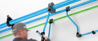
Air supply tube
to the receiver (usually copper or aluminum).
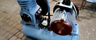
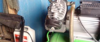
7) Compressor head
(usually placed under air cooling, in our case water/antifreeze cooling, for long-term operation it is desirable), the performance of the system as a whole depends on it.
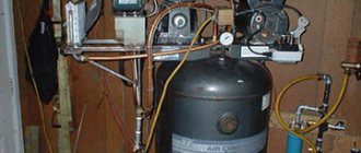
The pressure switch
is the heart of the compressor; in this box there is a pressure switch, usually adjusted to: 8 atmospheres, turn off the engine, reducing the pressure to 4-6 atmospheres starts the engine, and so on in a circle.
This unit also contains a pressure regulator with two pressure gauges - its task is to set the pressure required by the user for a specific tool, for example, a spray gun. Now about pressure gauges, as a rule there are two of them, one shows the pressure in the receiver, the second displays the air flow to the instrument. The output regulator has connecting fittings: either rapid or bypass. There is also a herringbone option). This unit has a small but extremely important part - a pressure relief valve (in common parlance, a fart). It is necessary in case of failure of the pressure switch. 9) Drain tap
- the function of freeing the receiver from condensation (and there will be condensation in any case).
Now let's look at the following non-obvious thing: why is such a long line from the head to the receiver made? Necessary for easier starting of the compressor. The principle of operation of this unit is simple - air from the compressor head passes through the main line through a check valve into the receiver. The compressor has turned off - the check valve has locked the air in the receiver, the air is standing in the tube. The compressor valves are not so tight and gradually bleed air, thereby the pressure in the tube drops. The motor needs a few moments to enter operating mode, and these few moments are provided by the tube and check valve.
Secondly, to reduce condensation at the outlet of the compressor, it is recommended to introduce air further from the outlet.
So, having understood the design of the compressor, and having understood some aspects, it was decided to sculpt a design that is not difficult to repeat.
1) Receiver
- a household propane cylinder 40-50 liters. (Before welding, degass, I am not responsible for your rash actions.) The following are welded into the body of the receiver: a piece of water pipe for a 1/2-inch back pressure valve, a piece of water pipe for a condensate drain tap, M12 nut for the emergency pressure valve (previously it was a valve for a 1/4 thread, I cut it with a die for M12). The air exits through the neck of the cylinder - a 3/4 inch bend, screwed into the cylinder (the cylinder has a 3/4 k thread (conical), screwed in without problems.
To ensure the correct operation of compressor equipment, various technical devices are used, among which is a check valve for the compressor. Without this unit it is almost impossible to imagine the operation of equipment designed for air compression.
Device Features
Check valves are used in many applications. Such devices most often work in tandem with some kind of tanks or compressors. The main task of a check valve is to prevent loss of pressure built into the system and limit the access of unwanted elements into the system.
In the absence of such a mechanism, the efficiency of the equipment decreases noticeably. For example, compressors are forced to work almost non-stop, which affects not only the operational life of the equipment, but also electricity bills.
Areas of application for check valves:
In addition to maintaining system pressure, check valves prevent liquid media from entering the compressor. With large volumes of distillation, as well as a serious load on the equipment, it is very important to maintain the tightness of the equipment. This point is also critical when working with gaseous compositions, especially hot ones.
In air conditioning and similar equipment, such valves perform two important functions:
Check valves are often used in ventilation technology, both in domestic and industrial areas. Equipment of this type can be seen in apartments - kitchens and bathrooms, in offices, catering establishments, as well as on construction sites and other technical facilities.
The check valve performs the following functions:
In a similar way, check valves are used in plumbing and other systems where it is necessary to shut off unwanted elements.
Types of clamping mechanisms
If the heating system has low power in a private house, or in an apartment, or a small industrial facility, products with a clamping mechanism are used.
The main part of the device is the spring. The part serves as a support for the membrane covering the seat. A washer is placed on the rod connecting to the handle, which serves as a support for the spring on top. The position of the washer and the pressing force on the membrane device are controlled using a handle.
The device has a simple design, is reliable, compact, and can be combined with all devices that are included in the safe group. The device can be purchased at a low price. The pressure indicator affects the compression force of the spring when the valve begins to operate. The elasticity indicator of the product regulates the range of settings.
Spring products operate based on the following actions:
1.water is directed to the valve of the product.
2.its movement is affected by the force of the spring, which restrains the flow.
3. The increased pressure becomes higher than the compression force, the rod mounted on the spool rises up.
4. The liquid enters the output pipe.
5.The amount of water in the system returns to normal.
6. The shutter closes with the help of a spring, returning to its original state.
The top layer of the spring is made of high quality brass material using hot stamping technology. Inside, the spring is steel, the membrane, the handle with seals are made of polymers.
Sometimes equipment is equipped with these settings at the factory. Some models require adjustments during installation, when commissioning work takes place.
Fuses are available in open or closed type. The open type is distinguished by the fact that excess liquid flows out of the pipeline; the closed type involves draining into the pipeline with reverse operation.
Lever-load fuses are not widely used. Autonomous systems with a boiler are installed infrequently. As a rule, they are found in large-scale industries, in pipes with a diameter of over two hundred millimeters.
In these fuses the main element is a weight instead of a spring acting on the rod. The load is hung on the lever device and moves along the length, influencing the force that presses the rod.
A lever-load type device tends to open when the operating pressure inside the spool exceeds the pressure values of the lever itself. Next, the liquid is removed through the discharge hole.
Attention! In order not to accidentally change the position of the rod on the lever part, the load is attached with bolts, covered with a casing, and a lock is installed.
The weight of the load and the length of the lever affect the pressure indicator and settings. This type of parting has a higher price than spring partings, but is not reliable.
Valves can be attached to flanged elements connecting pipes with a cross-section of fifty millimeters and above.
Features of shutters depending on the height to which they are raised.
Low-lift devices have valves that rise no more than five hundredths of a percent of the seat cross-section. The device that opens the part works on a proportional principle.
It has a low rate of passing liquid and a simple structure. Low-lift valves are mounted to pipes transporting liquid.
Full-lift mechanisms raise the valve higher, so they have good throughput and can remove a large volume of liquid at once.
Types of equipment
On the market you can find devices of various form factors, as well as purposes. Equipment is usually distinguished by design features, as well as by installation method. The choice of a particular device directly depends on the tasks assigned to it.
Design types of check valves:
The performance of the device is also affected by the material of manufacture. Check valves made of metal alloys are used in industrial structures where heavy loads are expected. Whereas plastic mechanisms can be seen in ordinary kitchens and bathrooms.
Regardless of the design, check valves can be:
The former can often be found in ventilation equipment. Ball valves are used in compressors, and other types are used in gas and plumbing lines. There are also advanced mechanisms with electromagnetic locking.
The cost of the latter, naturally, is noticeably higher. In this case, the blocking occurs not by means of a conventional spring spring, but by means of an electromagnet. But such valves are picky about distillation products and volumes, so manufacturers of industrial equipment most often give preference to more durable and reliable spring analogues.
Stands and mini-overpasses in the garage
A jack is a standard tool included with a car, but it is strictly prohibited to carry out even minor work under the bottom of the car when it is hung on a jack. And sometimes it is necessary to lift its entire front or back part.
In this case, you can’t do without goat stands.
Sometimes the stands are made in the form of mini-overpasses that the car runs over.
In addition to the general requirements listed below, an important element of such stands is the travel limiter at the front of the structure.
It doesn’t matter what they are made of, but the requirements are the same:
- stable wide support;
- safety margin for the design weight of the vehicle;
- minimal gaps between moving elements for height-adjustable stands.
The video shows the simplest coasters with a drive-in:
But in this case, we would recommend increasing the support base.
Check valve on compressor
This part is installed between the piston compressor cylinder and the receiver, and prevents air from returning from the storage tank back to the compression chamber after the unit is stopped.
Important! In addition, the return valve, by holding air in the receiver, allows for a smooth start-up of the equipment. If this part is removed, air will press on the piston and the engine will not be able to crank the crankshaft when starting.
In addition to the reverse, a safety valve must be installed on the compressor. This bypass valve is designed for emergency pressure relief if the pressure switch does not turn off the unit engine. The following photo shows the unloading valve, without which, for safety reasons, the compressor cannot be turned on.
Tips for choosing a part
When choosing a check valve for a compressor, you should know the size of the thread cut at the cylinder outlet . The thread may differ in different unit models. The easiest way is to take the faulty part with you and choose a similar one in the store.
If you need to change the return valve, for example, to a more reliable model, you should familiarize yourself with the technical characteristics of the new part. Some of them are not designed to work with high pressure compressors. Usually, the packaging for the return valve indicates the maximum pressure at which it can operate.
The temperature characteristics of this unit should also be taken into account. If the air, after compression, heats up to high temperatures, then you should not buy a plastic unit. Preference should be given to a metal check valve that is installed inside the duct.
Design and principle of operation
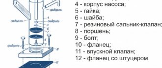
The return design includes the following elements (see figure below):
The return, in addition to the inlet fitting, has a side outlet through which it is connected to the receiver, and 1 thin outlet for connecting a pressure switch.
The check valve works according to the following principle. When the compressor is turned on, air passing through the cylinder suction valve enters the compression chamber, after which it exits through the outlet valve and enters the return inlet fitting (7). When a certain pressure is reached, the valve (6) together with the rubber ring rises and compresses the spring (4). As a result, a passage for air opens. The air moves into the housing cavity (3) and then into the outlet fitting connected to the receiver. After turning off the unit, valve (6), under the influence of a spring and air pressure from the receiver, returns to its place and closes the inlet.
Step by step assembly
How to make a foaming agent for foam concrete with your own hands?
The home handyman should proceed in the following order:
- disconnect the freon lines from the refrigerator compressor and unscrew it. Cleaned from dust, rust and treated with a corrosion converter in order to prepare for painting;
- change the oil in the compressor. To do this, open the sealed tube protruding from the body. This is done so that chips do not get inside. To do this, the tube is sawed in a circle with a small hacksaw or needle file, then the top is broken off. The oil is poured into a measuring container to find out its volume. Next, a portion of new oil in a slightly larger volume is injected with a medical syringe and the tube is clogged with a screw of a suitable diameter, wrapped with FUM tape;
- determine the purpose of the tubes for connecting to the freon line: supply power for a short time and see through which of them the air is sucked in and through which it is pumped. The tubes are marked.
Before applying power, the compressor should be oriented in space as it was in the refrigerator. This is due to the fact that the start of its motor is carried out using a starting relay: when power is applied, the solenoid core is retracted, then, after spinning the engine, it falls under the influence of gravity, opening the contacts of the auxiliary winding.
If the relay lies on its side, the core, of course, will not fall out and the starting winding will remain closed. There is usually a symbol on the relay cover to help you determine the correct position. An oil and water trap is connected to the compressor discharge tube. It is needed because the refrigerator compressor throws tiny droplets of oil into the discharge line during operation.
Further:
- bolt the compressor to the board, not forgetting about the correct orientation in space.
- Unscrew the shut-off and trigger device from the neck of the fire extinguisher. Clean the container from rust using mechanical and chemical (corrosion converter) methods. Add rust remover inside, shake and then drain;
- An adapter wrapped with FUM tape onto a ¾-inch thread is screwed into the neck of the fire extinguisher. FUM tape is wound in 3-5 layers;
- a pipeline cross or a herringbone fitting is screwed onto the adapter, also sealing the connection with FUM tape;
- a round recess with the same diameter as a fire extinguisher is cut out on the board next to the screwed compressor. From 3 sheets of plywood, using corners, a U-shaped structure is assembled - a holder for a fire extinguisher. A hole is cut along its diameter in a horizontal piece of plywood;
- Having screwed the holder to the board above the recess (corners are also used), install a fire extinguisher in it;
- A gasoline filter is connected to the compressor suction tube with a rubber hose. The pressure on this side is low and clamping is not required. It is enough that the hose tightly fits the filter and compressor pipes;
- An oil and water trap is connected to the outlet pipe of the supercharger using an oil-resistant hose.
Homemade compressor
High pressure is created on the discharge line, therefore all connections are fixed with automotive clamps (tightened with a screw). A check valve is connected to the outlet of the oil moisture trap (the air direction is indicated by an arrow on the body).
The outputs of the check valve and the cross or herringbone fitting are connected with a hose to one of the outlets of the cross or herringbone fitting screwed into the neck of the fire extinguisher-receiver and connected with a hose.
The crosspieces are screwed into the other branch pipes:
- pressure gauge;
- RD;
- valve.
Each threaded connection is sealed with FUM tape wound in 3-5 layers.
Connect the power supply:
- the neutral wire from the network is soldered to one of the two RD contacts;
- The 2nd RD contact is connected by wire to the compressor contact;
- the phase wire is soldered to the 2nd contact of the compressor.
Finally, the compressor is painted.
It is recommended to solder a toggle switch into the phase conductor gap - then you won’t have to unplug the device from the outlet every time.
How to make a check valve with your own hands
There are situations when the air compressor return valve has failed, and for some reason it is not possible to buy a new part. In this case, the part can be made by hand.
On the Internet you can find quite complex methods for manufacturing this unit using lathes, milling machines and other equipment. But there is still a way to make a simple homemade valve from improvised materials. A drawing of this unit is shown below.
To make a return you will need a metal pipe or tee, a spring, a coupling, a metal threaded plug and a ball.
The air check valve is manufactured as follows.
After this unit is ready, its inlet pipe is connected to the cylinder of the unit, and the second to the receiver.
Source
Possibility of making it yourself
There is no deep material meaning to independently manufacturing valves; purchasing parts will cost almost more than a ready-made commercially produced valve. Or the workshop at home must have precision drilling, turning and milling machines for independent production of device parts.
Very often, home craftsmen make valves with their own hands to test their own strength in design and assembly. We also produce original valves for domestic innovative beverage production plants or aquarium filtration and aeration systems. Next, the design and production technology of the valves will be considered:
- Ball for water.
- Gravity ball for water.
- Disc-shaped.
- Petal for ventilation.
Figure 3. Reed air valve design
The designs are simple and the technology does not require the use of expensive equipment. It is quite possible to make a simple check valve in a workshop at home. It is enough to have an average level of locksmithing skills.
Compressor valves - what are they?
An air compressor is a unit whose operating principle is based on compressing and supplying air to pneumatic equipment under the required pressure. Such installations are an indispensable element both in everyday life and in industry, being an autonomously functioning technical unit or being included in more complex electrical appliances (for example, climate control or refrigeration equipment). The schematic diagram of any compressor includes a working chamber and a valve system. And since these devices, like any other mechanisms, can break down, you need to know how they are designed, what types of valves there are, how to choose them correctly or make them yourself. More on all this in the material below.
Reasons for installing a fuse
Water circulates in the pipes of heating systems at a temperature of fifteen degrees.
Moving around the circle of a closed system, the coolant increases the temperature value, at the same time its volume increases. The pressure in the pipes also increases, increasing the load on pipe rolling devices.
If the pressure exceeds the norm, usually over three and a half bar, then the following occurs:
1. leaks in areas where parts are connected.
Types and principles of operation of valve mechanisms
Currently, the most common types of compressors are screw and piston units. At the same time, screw compressors, for example, those produced by the Belarusian plant REMEZA, are widely used in various industries, and piston compressors are used in everyday life. The latter can be found both in garages of car enthusiasts (compressors such as SO-7B, Forte VFL-50, etc.) and in life support systems for fish in aquariums (Resun compressors, etc.), as well as in household pneumatic tools.
Piston compressors are characterized by a simple design and a relatively small number of parts and components. There are many different designs of such compressor units, equipped with special plate valves that regulate the process of suction and injection of air during operation . Depending on the purpose of compressor units (their performance, power and operating pressure), three types of valve mechanisms can be found:
Inlet and exhaust valves
Inlet and outlet valve assemblies play such a role in the operation of compressor equipment.
Unloader and safety valves
Thus, the compressor pumps air into the receiver cycle by cycle until the specified pressure value is reached. This process is monitored by a special pressure switch (pressostat), which controls the operation of the electric motor by turning it on and off depending on the degree of air compression. As a rule, the pressure switch also includes a starting unloading valve. A pressure switch is connected between the output of the compressor head and the check valve (return valve), which is connected to the receiver and holds the compressed air there.
Important! The safety valve is responsible for relieving air pressure. Its functions include: ensuring a smooth start of the compressor and preventing the return of compressed air to the compression chamber after the engine is turned off.
The necessary pneumatic equipment is connected directly to the receiver, which can be additionally equipped with various devices (separators, filters, pressure equalizers, etc.).
I made and adjusted the air pressure switch for the compressor myself: find out how
The Russian market offers potential consumers a large number of different tools. Analyzing the state of the market, experts note a slight increase in the popularity of pneumatic tools.
However, while surpassing traditional types of power tools in basic parameters (power, reliability, durability), pneumatic tools require a source of compressed air.
Such a source is an air compressor, the purchase of which for one-time work is not economically feasible. That is why, widely used by professionals, pneumatic tools are rarely used in everyday life.
It is this device that regulates the air pressure in the compressor
Structurally, an air compressor is a device that can be manufactured by a person who has certain knowledge and skills in performing plumbing and electrical work at home. The responsible unit is an air pressure switch (pressostat), which you can install and adjust yourself. In addition, you can independently eliminate the simplest malfunctions of the pressure switch.
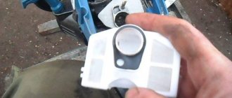
Pressure switch: purpose and principle of operation
A pressure switch is a device (actuator) with which the compressor motor is turned on or off. It is mounted on the tank (receiver) and connected to its check valve and the compressor head.
The pressure switch ensures that the entire product operates automatically. With its help, the required air pressure in the receiver is maintained.
The operating principle of such a relay is to use a normally closed contact in the electrical motor control circuit. Depending on the amount of air pressure in the pneumatic system, the power supply circuit is closed or opened. In this case, the engine starts with insufficient air pressure or is de-energized when the maximum value is reached.
As a working mechanism of the pressure switch, springs of different stiffness are used, which react differently to changes in air pressure in the receiver. The actuator is activated due to the forces of elastic deformation of the springs as a result of the pressure of the compressed air located in the receiver. In this case, the contact of the engine power supply circuit is closed or opened.
Accessories
In general, the pressure switch kit includes (maximum configuration):
- Unloading valve.
- Thermal motor protection relay.
- Mechanical switch.
- Safety valve.
The safety valve is an important element of the pressure switch
Each of these devices performs specific functions:
- Unloading valve - opens when the engine is stopped and relieves pressure from the pneumatic line. The next time the electric motor is turned on and accelerates, the check valve is locked, which makes it easier to start the entire device from the off state.
- Thermal motor protection relay - limits the current in the windings. A special adjusting element sets the permissible current strength, exceeding which will lead to shutdown of the electric motor.
- Mechanical switch - turns on the automatic operating mode of the product (AUTO position) and allows you to forcibly turn off the engine (OFF position).
- Safety valve - is activated if the compressor pressure switch fails and produces an emergency release of compressed air from the receiver, preventing pressure from increasing above the permissible value.
Connection diagram
Existing air pressure switches for a 220 V compressor are used in various load connection schemes.
- In the case of using a single-phase electric motor, use a pressure switch with two contact groups, designed to operate in a 220 V network.
- If there is a three-phase motor, a relay with an operating voltage of 380 V, equipped with three contact groups, is used.
ATTENTION! It is not recommended to use a single-phase air pressure switch (220 V) to connect a three-phase motor.
The pressure switch is connected to the electrical circuit of the compressor using special contactors (connectors) built into its housing.
Connecting flanges
The pressure switch is connected to the receiver using a threaded flange with a standard 1/4 inch internal thread. Many pressure switches are equipped with a 4-sided flange, which allows, if necessary, to connect up to three additional devices to it, for example:
- Pressure gauge.
- Safety valve.
- Unloading valve.
If there is no need to connect additional devices, then the flanges are closed with special plugs.
IMPORTANT: Flange threaded holes are 3/8" or 1/2" threaded. Additional devices must also have appropriate threads.
Receiver, relay - all assembled, excellent compressor
Installation
The compressor pressure switch is mounted directly on the compressor tank (central flange with 1/4 inch thread). If necessary, additional devices are installed through loose flanges. If there is no need for additional devices, then the threaded holes of the flanges are closed with special plugs.
The control circuit for turning the compressor motor on and off is connected to the contacts of the pressure switch.
ATTENTION! If the load current exceeds the permissible power of the relay contacts, it is necessary to use a network contactor (magnetic starter) when connecting.
Settings
Serially produced pressure switches do not require adjustment. However, during the operation of the compressor, situations may arise in which it is necessary to change the response thresholds of its actuator. The procedure for performing adjustment work:
- Determine the range of change in compressed air pressure.
- Disconnect the product from the electrical network.
- Remove the top cover of the pressure switch.
- Set the required values of the relay response thresholds using two special adjusting spring-loaded screws located under the cover. The set values are controlled using a pressure gauge.
- Adjustment of the upper threshold of the pressure switch, at which the electric motor is turned off, is carried out using the adjusting screw, marked with the symbol “P”. To change the response threshold of the actuator, it is necessary to rotate the screw in the direction of the arrow in the direction corresponding to the designations “+” and “-“.
- Setting the lower threshold of the pressure switch, at which the engine will automatically turn on, is done by rotating the second adjusting screw with the symbol “5P” towards the designations “+” and “-“.
- Reinstall the top cover of the air pressure switch.
DIY pressure switch
Having taken on the task of making an air compressor on their own, some amateur craftsmen may decide to make a pressure switch with their own hands.
Making your own equipment is interesting, practical and very economical
On the Internet you can find options for homemade devices, for example, made from a thermostat from a refrigerator or made using parts from CDs and plastic bottles.
However, it should be noted that their design cannot be compared with the design of a commercially produced compressor pressure switch.
In addition, the use of a homemade device, in the event of a sudden failure, can lead to an emergency with unpredictable consequences for others.
TIP: given that the air pressure switch is one of the most critical components of the compressor, it is better to install an industrial pressure switch even in a homemade compressor.
Relay malfunctions and their elimination
There are several characteristic faults inherent in pressure switches. Most often, in these cases, the relay is simply replaced with a new one, but there are also breakdowns that can be fixed with your own hands. Among them the most common are:
- Air leakage through the pressure switch when the compressor stops. The cause of the malfunction is contamination of the receiver check valve. To eliminate the malfunction, it is necessary to bleed the compressed air from the reservoir, remove the valve plug and clean the valve seat and O-ring.
- When the compressor is operating, compressed air leaks through the pressure switch. This is due to a breakdown of the start valve. The malfunction is eliminated by replacing the start valve gasket.
- The compressor starts to turn on frequently. This occurs due to vibration of the compressor and a shift in the position of the adjusting screws. It is necessary to check the thresholds for turning on and off the pressure switch and adjust them according to the instructions given in the “Settings” section.
- The compressor does not turn on. In this case, there may be several reasons, but one of them is related to the burning of the contact group of the pressure switch. Burning of contacts occurs due to electric spark erosion that occurs when the contact group opens.
You can fix the problem:
- replacing the pressure switch;
- by cleaning the contacting surfaces (extends the life of the device by 2-3 months);
- replacing the contact group with a new one (not all modifications are commercially available);
- by repairing the contact group yourself (replacing contacts in the terminals).
DIY contact group repair
Having started the repair, it is necessary to bleed the air from the receiver, turn off the power to the compressor and dismantle the pressure switch. Repair work is carried out in the following order:
- Remove the protective cover.
- Disconnect the wires going to the contact group.
- Using a flat-head screwdriver, remove the contact group and terminal holder. You need to remember the position of the return spring, which can “shoot” when dismantling the contact group. Pull the terminals out of the holder and drill out the burnt contacts from them.
- Take a piece of copper wire 10 mm long and insert it into the drilled hole. The diameter of the wire should ensure a tight fit in this hole.
- Crimp the wire on both sides in such a way as to ensure its secure fastening in the hole.
- If necessary, repeat the same procedure with the remaining terminals.
- Assemble the contact group by performing the necessary operations in reverse order.
- Place the contact group in place and close the pressure switch with the lid.
WATCH VIDEO INSTRUCTIONS
INTERESTING: a service representative who came to fix a compressor malfunction will insist on replacement if the pressure switch breaks. He will not clean or change the parts of the contact group, since performing such work will cost the consumer more than purchasing and installing a new one.
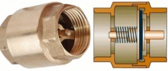
Check valve
A check valve (return valve) is a device that allows compressed air to flow in only one direction . Structurally, it is assembled (see figure) in a metal case (item 3), inside of which the following are located:
On a note! The check valve has a branch for connecting it to the receiver and a small branch for connecting a pressure switch.
Operating principle
The reverse action valve works as follows. Passing through the outlet valve of the piston cylinder, the compressed air enters the return pipe through the inlet fitting (pos. 7). Having reached a certain pressure, the air lifts the internal shutter (pos. 6) and passes through the cavity in the housing (pos. 3) into the storage tank of the receiver. When the compressor is turned off, the spring (item 4) returns the internal shutter to its place, blocking the path of air from the receiver back into the piston cylinder.
Varieties
On the domestic market you can find compressors with returns made of three different materials: aluminum, plastic and brass. At the same time, the aluminum part differs from its analogues in its high reliability and durability. It is built inside the air duct that connects the piston cylinder to the receiver, and is capable of operating under high temperature conditions (up to 200°C). Whereas a plastic return line is installed in budget models operating at a low temperature of the working environment. As for valves made of brass, they are widely used. Such return valves are quite reliable and perfectly maintain their performance characteristics in cases where the air temperature during compression does not exceed 140°C.
Another story
How to make a foam generator for foam concrete with your own hands: drawings, assembly
Let's start by drawing up the technical requirements for the fruit of our own engineering. Let's say it all started with the purchase of a new double-action airbrush. Therefore, the issue of manufacturing a compressor unit with a receiver became extremely necessary.
A dual action airbrush has the ability to control the air flow as well as lock and open the air duct. In Europe, such a device is used with a separate compressed air cylinder. So, a compressor with a reservoir serves as a container for collecting air, and the airbrush uses this air.
Of course, the main component is the compressor. Here an old refrigerator will come to the rescue, from which you can remove an excellent compressor. To do this, you can go through websites that sell refrigeration equipment.
Next, we’ll consider an option like a do-it-yourself compressor receiver. Here, of course, you need a reservoir that was made to contain gases or can withstand high pressure. It is optimal if such a container meets the requirements of GOST. Therefore, we immediately exclude containers such as a plastic canister or bottle. Let's look at the tank options:
- Carbon dioxide fire extinguisher. Withstands pressure - 10 atmospheres. Capacity – 3 l/5 l/10 l. Cons: the inlet has a metric thread.
- Hydraulic accumulator. Good capacity capacity, with low operating pressure. There is a convenient thread at the entrance. Disadvantages - it needs fine-tuning, since from the inside it is divided into a membrane that contains carbon dioxide. The membrane must be removed.
- Oxygen balloon. Withstands high pressure. Cons: Only extremely heavy models are available.
- Propane tank. In general, they are similar to a fire extinguisher, but the manufacturer does not recommend their use for compressed air.
Links
Once we have decided on the compressor and selected a suitable product for the receiver, the next step is to combine them. In addition, it is necessary to solve the problem of air supply to the airbrush.
You can start with a unit that is attached directly to the receiver and will ensure air distribution. It must be recalled that the key factor is its compatibility with the receiver connector
Next, we pay attention to the pressure switch, which will ensure that the compressor is turned off and on
The best option for the relay would be RDM-5, which is used for plumbing systems. This model is widely available for sale, and the good thing is that its connecting element is designed for external inch threads.
simple compressor
Then we determine the pressure indication in the receiver. For this we need a 10 atmosphere pressure gauge; it also has a suitable connection size. And we will also need a static device.
Next we are working on the air preparation unit. Pressure must be applied to the hose that leads to the airbrush. Accordingly, there is a need for a gearbox with a pressure control limit of up to 10 atmospheres, and it is desirable that it be accompanied by a pressure gauge and an oil separator filter.
Using a pressure gauge, we will monitor the pressure, and the filter will ensure that particles of compressor oil do not enter the receiver. But it should not be confused with a lubricator filter, which performs a diametrically opposite function.
Let's continue collecting materials, and it's time to prepare fittings, turns, and tees. We take inches as the base size. To determine the quantity, you need a diagram of the air distribution and preparation unit.
We will also need external and internal adapters. If you wish, you can make a plan diagram of how to make a compressor. The next stage is the placement of the finished structure. Chipboard boards may be an option.
Of course, in order not to swear while moving the station around the workshop, it is advisable to immediately resolve the issue with the roller legs. Any furniture store will be happy to sell them to you. To save space, you can make a two-story structure. True, long bolts may be needed. So, let’s summarize the planning stage with a list of components:
- Compressor;
- Receiver;
- Pressure switch;
- Pressure gauge;
- Filter reducer;
- Emergency valve;
- Fittings, adapters;
- Plumbing gaskets, fum tape, sealant;
- Cables, switch, plug;
- Flexible oil-resistant hose;
- Chipboard sheet
- Roller legs, bolts, nuts, washers and tools.
Safety valve
The relief valve (another name is safety) valve serves for emergency release of pressure and is the final device that protects the pneumatic equipment connected to the compressor from damage.
Attention! It is not recommended to operate the compressor without a safety valve.
Experts also include the following types of relief valve:
Despite minor design differences, their operating principle is identical to a safety valve.
Operating principle of the safety valve
Compressor equipment that is not intended for use in industrial environments is equipped with spring-loaded safety valves. When such a compressor operates in normal mode, it is closed (see diagram). In this case, the air pressure on its plate is balanced by a calibrated spring, which prevents the locking mechanism from opening. If the pressure suddenly increases above the set value, the pressing force of the plate against the nozzle decreases and the valve begins to open. This releases excess air, after which the locking mechanism can return to its place.
Important! If the relief valve does not return to its place for a long time, then the compressor must be turned off and the cause that caused the unauthorized increase in pressure must be eliminated
Bypass valve
The bypass (or overflow) valve maintains the pressure of the working medium at a given level. To do this, through the existing branch there is a constant, and not one-time or periodic, as in a safety valve, removal of an excess amount of the working medium (compressed air, gas, liquid), which ensures pressure stability in the system. Such valves are used, for example, in turbochargers installed on automobile internal combustion engines.
Unloading valve
The unloading valve ensures the release of compressed air remaining in the manifold between the piston block and the return line when the compressor stops. In this case, the pressure at the compressor outlet is reduced to atmospheric pressure. In general, the presence of an unloading valve makes it possible to:
In addition, the unloading valve is used in cases where it is not possible to turn off the mechanical drive of the connected pneumatic equipment . Install it at the compressor outlet in front of the return line.
So, the more productive and powerful the compressor equipment, the more complex the valve system. The simplest check valve for use in a household low-pressure compressor can be made by yourself. But for the installation to work correctly, it is recommended to purchase a factory-made part.
Air compressor made from refrigerator and fire extinguisher parts
Electric turbine for a car. is it possible? Is it possible to do it yourself? only the real truth
This unit operates almost silently. Let's look at the diagram of the future design and make a list of the necessary components and parts.
1 — tube for filling oil; 2 - starting relay; 3 - compressor; 4 - copper tubes; 5 — hoses; 6 — diesel filter; 7 — gasoline filter; 8 — air inlet; 9 — pressure switch; 10 — crosspiece; 11 - safety valve; 12 - tee; 13 — receiver from a fire extinguisher; 14 — pressure reducer with pressure gauge; 15 — moisture-oil trap; 16 — pneumatic socket
Necessary parts, materials and tools
The main elements taken are: a motor-compressor from a refrigerator (preferably made in the USSR) and a fire extinguisher cylinder, which will be used as a receiver. If they are not available, then you can look for a compressor from a non-working refrigerator at repair shops or at metal collection points. A fire extinguisher can be purchased on the secondary market or you can involve friends in the search, who at work may have written off fire extinguisher, fire extinguisher, fire extinguisher for 10 liters. The fire extinguisher cylinder must be emptied safely.
In addition you will need:
- pressure gauge (as for a pump, water heater);
- diesel filter;
- filter for a gasoline engine;
- pressure switch;
- electric toggle switch;
- pressure regulator (reducer) with pressure gauge;
- reinforced hose;
- water pipes, tees, adapters, fittings + clamps, hardware;
- materials for creating a frame - metal or wood + furniture wheels;
- safety valve (to relieve excess pressure);
- self-closing air inlet (for connection, for example, to an airbrush).
In addition, you will need tools: a hacksaw, a wrench, a syringe, as well as FUM-leta, anti-rust, synthetic motor oil, paint or enamel for metal.
Preparing the motor-compressor
Three tubes come out of the motor-compressor, two of which are open (air inlet and outlet), and the third, with a sealed end, is for changing the oil. To find the air inlet and outlet, you need to briefly apply current to the compressor and put the appropriate marks on the tubes.
Next, you need to carefully file or cut off the sealed end, making sure that no copper filings get inside the tube. Then drain the oil inside and use a syringe to fill in motor, synthetic or semi-synthetic. You can seal the tube by selecting a screw of a suitable diameter, which must be wrapped with FUM tape and screwed into the hole. Sealant can be applied over the joint. If necessary, paint the surface with enamel.
Preparing the receiver
You need to remove the shut-off valve (SPV) from the empty fire extinguisher cylinder. Clean the outside of the container from rust and dirt, and pour “anti-rust” inside and hold it for as long as indicated on the product label. Let it dry and screw on the lid with the hole from the ZPK. We screw the adapter into the hole (if necessary) and attach the cross.
We attach a pressure switch to the upper branch pipe, on one side we screw in a tee and connect a pressure gauge, on the other we mount a safety valve or a valve for bleeding air manually (optional). Where required, we use adapters. If necessary, we paint the balloon.
Circuit assembly
On an assembled frame (for example, a strong board on wheels or a structure made of strong corners or pipes) we attach the cylinder, and on it or next to it - a motor-compressor, laying a rubber gasket. We connect first a gasoline and then a diesel filter to the incoming air pipe of the compressor. This must be done if the compressor is designed to operate an airbrush, in order to eliminate the slightest air contamination. And since the diesel filter is thinner, it is installed after the gasoline one. If copper tubes have lost their shape during dismantling, they need to be flared.
The power supply is connected through a toggle switch, a pressure switch and a start relay. We protect all connections with electrical tape or heat shrink.
It is important to install the starting relay in the correct position - according to the arrow on its cover, otherwise the device will not work correctly.
1 - toggle switch; 2 - pressure switch; 3 — compressor start relay; 4 — relay position arrow; 5 — connection of the relay to the compressor windings; 6 - compressor
We connect the output air tube from the compressor through an adapter to the inlet of the receiver. After the pressure gauge, we install a gearbox with a remote moisture-oil trap, and behind it a hose with a self-locking air outlet.
The end result, with due diligence, works well and looks aesthetically pleasing.
Safety check valve for a compressor: types, design, DIY production
In order to ensure the correct operation of compressor units used almost everywhere today, a number of additional technical devices are used, one of which is a check valve for the compressor. Such a valve, which is equipped with the vast majority of compressor units today, also protects them from premature failure and ensures smooth starting.
Check valve on compressor
Bases for mounting the protective element
The heating system receives water with a temperature of no more than 15°C. Moving inside the system, the coolant used gradually heats up, increases in volume, and accordingly, the pressure becomes greater. Due to its increase, the load on the products increases.
If the pressure rises above 3.5 bar, you may encounter the following troubles:
- leaks in pipeline elements;
- breakdowns of parts made of polymer;
- explosion of a heating fuel tank;
- short electrical circuit in the electrical system.
In standard solid fuel heating boilers, heat transfer slowly increases the temperature. The liquid used as a coolant overheats quite quickly due to the fact that the heat generator operates by inertia.
To prevent rapid overheating, it is necessary to install a special safety group. It consists of such elements as:
- pressure gauge for measuring pressure level;
- air vent to eliminate air masses;
- safety safety valve.
The operating principle of the valve is as follows:
- During active combustion of solid fuel, water is naturally heated to the required temperature.
- It blocks the air flow, causing the fire to go out.
- The firebox produces heat.
- The coolant heats up to 95°C.
- The liquid composition boils and begins to evaporate.
- The pressure increases abruptly.
- The safety valve is activated, which monitors the safety of the heating system.
- The device instantly activates the shutter, allowing the heated steam to escape.
- The pressure drops to standard.
- The safety valve used to protect the heating system returns to its previously set position.
The protection valve is installed in boilers of a special solid fuel type, in more modern models - steam and conventional furnaces, where there are water circuits.
If you buy modern heating systems offered by well-known brands, you will not have to purchase additional safety protective components. This element is present in the equipment initially.
In older models, you will need to install the protective safety valve yourself. It is mounted inside the heat exchanger or in a pipe that is connected to the boiler.
Purpose, design features and scope of application
A check valve installed at the outlet of the compressor head allows compressed air to pass in only one direction - to the receiver or any other reservoir. Thus, this valve prevents the return of compressed air located in the receiver or other elements of the pneumatic system back to the compressor. The greatest risk of compressed air returning from the pneumatic system to the inside of the compressor is during breaks in the operation of the device (if the compressor discharge valves do not fit tightly to the seats), as well as at the time of its startup.
What to pay attention to
Before purchasing a valve, first take into account such a circumstance as the intensity of the existing air flow. In other systems it may be liquid or gas. This circumstance directly affects the startup and error-free operation of the installed valve.
In addition, you need to take into account that the performance coefficients of the air purifying unit are interrelated with the power data of the pumping device, be it a pump or a fan. When choosing a valve, take into account the temperature conditions in the room and the environment in which the device will be installed. The level of environmental pollution is also significant. For example, a unit of the “butterfly” variety, when exposed to a stream of cold air, begins to significantly slow down. This can lead to poor fusion between the duct and the mechanism as a whole. The cost of the valve can fluctuate insignificantly and directly depends on the technical parameters and the company that developed the mechanism .
Main varieties
Check valve systems, depending on their design, can be:
Direct type check valve for high pressure stations
The material of manufacture may also vary, depending on what environments such a device will come into contact with during operation. In particular, it can be either metal alloys of various types or plastic.
Depending on the type of shut-off element used, check valves can be:
The last three types of devices are used for installation in ventilation systems. Among check valves and safety valves installed on compressors, ball-type devices are the most popular, since they are less critical to contaminants present in the working environment.
Check valves with cone (a), flat (b) and spherical (c) shut-off elements
Among the most modern valve systems, it is worth noting electromagnetic type devices, in which the movement of the valve is controlled not by a spring, but by an electromagnet. Meanwhile, due to the rather high cost and not too much reliability, such devices are not very popular, inferior to cheaper and time-tested spring analogues.
Air compressor made from refrigerator and fire extinguisher parts
This unit operates almost silently. Let's look at the diagram of the future design and make a list of the necessary components and parts.
1 — tube for filling oil; 2 - starting relay; 3 - compressor; 4 - copper tubes; 5 — hoses; 6 — diesel filter; 7 — gasoline filter; 8 — air inlet; 9 — pressure switch; 10 — crosspiece; 11 - safety valve; 12 - tee; 13 — receiver from a fire extinguisher; 14 — pressure reducer with pressure gauge; 15 — moisture-oil trap; 16 — pneumatic socket
Necessary parts, materials and tools
The main elements taken are: a motor-compressor from a refrigerator (preferably made in the USSR) and a fire extinguisher cylinder, which will be used as a receiver. If they are not available, then you can look for a compressor from a non-working refrigerator at repair shops or at metal collection points. A fire extinguisher can be purchased on the secondary market or you can involve friends in the search, who at work may have written off fire extinguisher, fire extinguisher, fire extinguisher for 10 liters. The fire extinguisher cylinder must be emptied safely.
In addition you will need:
- pressure gauge (as for a pump, water heater);
- diesel filter;
- filter for a gasoline engine;
- pressure switch;
- electric toggle switch;
- pressure regulator (reducer) with pressure gauge;
- reinforced hose;
- water pipes, tees, adapters, fittings + clamps, hardware;
- materials for creating a frame - metal or wood + furniture wheels;
- safety valve (to relieve excess pressure);
- self-closing air inlet (for connection, for example, to an airbrush).
Another viable receiver came from a tubeless car wheel. An extremely budget-friendly, although not very productive model.
Wheel receiver
We invite you to watch a video about this experience from the author of the design.
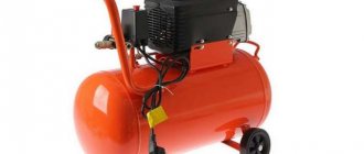
A compressor is an indispensable item in any garage. But buying a good compressor is not cheap. Craftsmen share their experience on how to assemble a compressor for a garage with your own hands from simple and affordable parts.
An air compressor is a reliable assistant. Using a directed jet of compressed air, it is easy to clean your car from dust and increase the pressure in pneumatic tools for the garage.
Using a stream of compressed air, you can always perform high-quality painting of individual parts or the entire car body.
The main requirement for good compressor operation is that the air must flow under uniform pressure and be free of dust and oil. If during painting there are such particles in the air supplied by the compressor, then the paint layer is applied unevenly.
A good factory-made compressor is not cheap, but can be used both for professional painting and for performing high-quality, effective airbrushing. Having studied the principles of operation of such a device, you can make a high-quality homemade one.
The principle is simple - compressed air under pressure is collected in a sealed container (receiver). The pressure in the container can be increased either mechanically (manually) or using automation. Constantly pumping up the pressure manually is inconvenient; automatic adjustment is easier to operate.
In compressors with automation, you only need to ensure that the oil in the pump is regularly changed to prevent rapid wear of rubbing parts.
A stream of compressed air flows through the fitting to the desired device (for painting, for cleaning or for blowing hoses).