Measuring the amount of electricity passed per unit time through the cross-section of a conductor (current strength - I) is traditionally carried out when the circuit is broken and at that moment a special device is connected to it to perform the measurement. Current clamps are used to determine the intensity of the electromagnetic field that occurs near a conductor. Their use speeds up and simplifies the measurement process.
What it is
Electric clamps directly serve specialists for prompt and reliable measurement of various parameters of electric current: its voltage, power and others. In this case, there is no need to break the chain or disrupt its operation. Depending on what values need to be measured, the following mites are distinguished:
- Ammeter;
- Ampere-voltmeter;
- Wattmeter;
- Phase meter.
Current clamps
This measuring device in any configuration - from the simplest to the most professional - consists of a magnetic core, a button that records measurement data, a switch (for selecting the measurement range and the necessary additional functions of the device), various connectors for additional connection of probes and a small built-in monitor/ display.
Current clamps
The most popular and also easily applicable are clamp-on ammeters, used to obtain the parameters and characteristics of alternating current; they are also called current meters. Let's figure out why current clamps are needed.
Electrical clamps easily allow you to:
- Determine and control actual loads in electrical networks;
- Measure the power of various electrical appliances;
- Monitor the operation of electricity meters and its consumption (for example, to verify electrical meter readings).
Such current clamps can be used at voltages up to 10 kilovolts.
Design
In current clamp meters, two main working units can be specified:
Design of pliers
- The grips contain the windings of the transformer.
- The handle contains an ammeter or other measuring device.
An electric current is induced in the transformer windings, the characteristics of which are determined by a built-in measuring device. It must be taken into account that the induced current has a different value compared to the original one. To obtain an accurate value, a recalculation is required.
What do clamp meters measure?
Before purchasing this device, you need to decide for what purpose the electrical clamps are intended.
They are a transformer with a connected ammeter. The device itself is the primary winding of the transformer. Placing a conductor inside it helps induce an electric current into the winding due to the resulting electromagnetic field. Then it goes to the secondary winding of the coil, the readings from which are read by an ammeter. The readings of this device are recalculated adjusted for the transformation ratio indicated on it. A transformer does not work with direct current, so the current clamps described are for alternating current.
Clamp meters manufactured today are used for values measured at direct current. A Hall sensor is placed in place of the ammeter, which detects the presence and voltage of the electromagnetic field.
Using these devices, the following measurements are made:
- actual network load;
- the accuracy of readings of various equipment intended for electricity metering, comparing the readings on them with the readings obtained when measuring with clamps;
- power of household and professional electrical appliances.
Current clamps for direct current are more expensive than their counterparts for alternating current, but they are more accurate and have improved quality indicators. The tool, used in conjunction with a digital multimeter, allows the user to save the user from calculating the desired value, since the device has a built-in calculator.
Definition
Current clamps - allow you to find out the current strength or other characteristics without a break in the electrical circuit. This instrument works on a different principle - it determines the characteristics of the electric current based on the parameters of the magnetic field.
Scope of application: DT-3353 Electrical clamps, wattmeter
• Housing and communal services, in everyday life; • Maintenance and diagnostics of power equipment; • radio electronics and diagnostics of electrical devices
Current clamp with multimeter and power meter functions DT-3353
Current clamps DT-3353 are designed for measuring the parameters of single-phase and balanced three-phase electrical networks. The device allows for non-contact measurements of current and contact measurements of electrical parameters (voltage, active, apparent and reactive powers, power factor cosθ, phase angle and active energy).
DT-3353 Features: • Analysis of single-phase and balanced three-phase systems • True RMS (voltage and current) • Large 4-digit backlit LCD display • USB, software • Display of minimum or maximum measured value • Active power/apparent power/ratio power • Hold readings on display • Auto range • Out of range indication • Auto power off when idle • Manually store and read data (99 values)
Technical characteristics of DT-3353:
| AC voltage measurement range | up to...750V |
| AC voltage measurement resolution | 1 |
| AC voltage measurement accuracy | ±(1.2% +5 e.m.r.) |
| AC current measurement range | up to...1000A |
| AC current measurement resolution | 1 |
| AC current measurement accuracy | ±(2% +5 e.m.r.) |
| Active power measurement range | 0.01…750.00 kW |
| Active power measurement resolution | >1000kW: 1 <1000kW: 0.1 <100kW: 0.01 |
| Active power measurement accuracy | ±(3% +5 e.m.r.) |
| Apparent power measurement range | 0.01…750.0 kVA |
| Apparent power measurement resolution | >1000kW: 1 <1000kW: 0.1 <100kW: 0.01 |
| Active power measurement accuracy | ±(3% +5 e.m.r.) |
| Reactive power measurement range | 0.01…750.0 kVAr |
| Reactive power measurement resolution | >1000kW: 1 <1000kW: 0.1 <100kW: 0.01 |
| Reactive power measurement accuracy | ±(4% +5 e.m.r.) |
| Power factor | 0,300…1 |
| Power factor measurement resolution | 1 |
| Power Factor Accuracy | ±(0.022% +2 e.m.r.) |
| Phase angle measurement range | 0°…90° |
| Phase angle measurement resolution | 1° |
| Phase angle measurement accuracy | ±2° |
| Current frequency measurement range | 50…200 Hz |
| Discreteness of current frequency measurement | 1 Hz |
| Current frequency measurement accuracy | ±(0.5% +5 e.m.r.) |
| Active energy measurement range | 0.001…9999 kW/h |
| Active energy measurement resolution | >1000kWh: 1 <1000kWh: 0.1 <100kWh: 0.01 <10kWh: 0.001 |
| Plier grip diameter | 52 mm |
| Display | 2 indicators: 5- and 4-digit, backlit |
| Measurement speed | 2 changes/s |
| Allowable input current | 1000A |
| Allowable input voltage | 750V |
| AC response | True RMS |
| Automatic shutdown | After 30 seconds of inactivity |
| Battery | 9V Krona battery |
| Working conditions | +5…+40°С, ≤ 80%RH, ≤ 7000 m above sea level. seas |
| Storage conditions | –20…+60°С, ≤ 80%RH |
| Dimensions | 294×105×47 mm |
| Weight | 536 g |
| Active energy measurement accuracy | ±(3% +2 e.m.r.) |
Complete set of current clamps DT-3353:
| Name | Quantity |
| 1. Device | 1 PC. |
| 2. Test lead (black) | 1 PC. |
| 3. Test lead (red) | 3 pcs. |
| 4. Crocodile clip | 4 things. |
| 5. Test probe (black) | 1 PC. |
| 6. Test probe (red) | 1 PC. |
| 7. USB cable | 1 PC. |
| 8. CD with software | 1 PC. |
| 9. Case bag | 1 PC. |
| 10. Krona type battery (inside the device) | 1 PC. |
| 11.Operation manual | 1 PC. |
RF Type Approval Certificate for current clamps from CEM.
This is interesting: Voltage drop in the apartment when consumers are turned on
Working principle of clamp meters
The principle of operation of electrical clamp meters is in many ways similar to the operation of a substation - there is an instrument transformer and a device for measuring electrical parameters: current, voltage, etc. As you know, any transformer, including a measuring one, consists of two or more windings.
In electrical measuring clamps, the first winding is a conductor, the current strength of which we measure. The second winding with a large number of turns is located in the tongs themselves. The device analyzes the current in the secondary winding and, taking into account the known transformation ratio, calculates the amount of electric current in the conductor.
In the figure below you can clearly see the operating principle of this measuring device.
It is worth noting that measuring current with electrical measuring tongs is not a difficult and very convenient task. You just need to set the required value on the handle, open the handles, pass the conductor through the pliers and release one handle.
Tags
measuring current in measuring current in measuring current in measuring current in measuring current in measuring current in measuring. Current clamp meter works of current clamp meter elements of current clamp meter with direct current not Current clamp meter is used current clamp meter current clamp meter electrical clamp meter. Current clamp meter for current clamp meter current clamp is the switch clamp for current clamp meter To measure current To measure current To measure voltage which is carried out by government and instruments
cables working more legal test number
Types of current clamps
The types of mites depend on the appearance, design and type of output. They are usually divided into the following categories:
- Analog or pointer. They consist of a transformer with one turn and a measuring apparatus connected to the secondary winding. Such devices are cheaper and more visual, but have increased sensitivity to mechanical influences and vibrations. Analog meters are typically rated for a specific frequency;
- Digital or electronic. In them, readings are displayed on a digital display using microprocessor calculations, and can be configured to display various values;
- Multimeter. This is a universal tool for measuring all electrical parameters. In it, the pliers can be built directly into the body. The functions and characteristics of a multimeter are determined by its price and model. Often they have the same Hall sensor;
- Clamps for high-voltage networks. Their main purpose is to measure current parameters in networks whose voltage exceeds 1 kV. This type has increased protection and insulation and can be attached to dielectric rods to prevent the electrician from getting too close to the network.
Connection diagram for a multimeter for measuring electric current
Measurement modes
There are 2 methods for determining current strength:
- direct;
- indirect (inductive) measurement.
The first method is carried out by connecting an ammeter to an open circuit. An electric current passes through the device, information about the value of the I value appears on the display.
Advantages of this method:
- measurement accuracy depending on the class of equipment;
- ease and accessibility of measurements.
Flaws:
- it is impossible to measure large amounts of electric currents due to the design features;
- without a break it is impossible to measure the parameters of the circuit;
- measurements are performed only in the circuit that is connected to the device.
Question of price
Again, differences in price are especially clear when comparing Russian and foreign products. In the lines of budget solutions of domestic companies you can find models for 1-2 thousand rubles. Higher quality equipment that can be used to solve professional problems is estimated at 3-4 thousand rubles. By the way, budget foreign measuring clamps are in the same range. The price of professional devices from Fluke or Sturm can reach 6-7 thousand. This is the level of the same wireless technology, which is distinguished by both high measurement accuracy and durability.
How to measure current using a transformer
When a conductor is passed through the terminals of the device, current passes through these terminals, acting as the iron core of a power transformer. Next, the current flows into the secondary winding, which is connected through the meter input shunt. Due to the ratio of the number of secondary windings to the number of primary windings wound around the core, the current entering the input is much less. Typically, the primary winding consists of one conductor, around which the jaws are clamped.
If the secondary winding has, for example, 1000 turns, then the current in the secondary winding will be 1000 times less than that flowing through the primary winding. Thus, 1 ampere in the conductor being measured will produce only 1 milliampere at the instrument input. By increasing the number of turns in the secondary winding, powerful currents can be easily measured.
How to measure direct current, because it flows through conductors with a fixed polarity? Here the magnetic field around the conductor does not change, and it is impossible to record the corresponding readings in the usual way. Therefore, the clamps around such a conductor are closed with some gap (see Figure 2).
Operating principle
Current transformer clamps
The principle of operation of current clamps - current transformers is based on the fact that the current flowing in a wire creates a vortex magnetic field, the lines of force of which surround the conductor. A secondary winding, connected to a secondary electrical measuring device, the scale of which is graduated in current units, is wound on a detachable conductor to allow the conductor to be inserted into the window of the magnetic circuit, made of soft magnetic ferromagnetic material. Thus, this current transformer has two windings, the primary - one turn is a wire with the measured current and a multi-turn secondary winding.
In accordance with Faraday's law of electromagnetic induction, an emf is induced in the secondary winding, the magnitude of which is directly proportional to the rate of change of the magnetic flux covered by the secondary winding. Since the magnitude of this flux is directly proportional to the measured current, by measuring this EMF, the rate of change of current in the wire (time derivative) is indirectly measured, and by integrating this EMF over time, you can obtain the true instantaneous value of the current in the wire.
Since such clamps are usually used to measure currents of industrial frequency, the frequency of which deviates slightly from the nominal (50 or 60 Hz), and the shape of the current is close to sinusoidal, with sufficient accuracy for practical measurements we can assume that the root-mean-square value of this EMF is directly proportional to the root-mean-square value measured current. Thus, by measuring the voltage on the secondary winding, it is possible to determine the effective value of the measured current.
Clamps with Hall sensor
The magnetic circuit of such clamps does not differ in design from that of clamps with a secondary winding, but a sensor is placed in the open gap of the magnetic circuit, the operation of which is based on the Hall effect. The primary current generates a magnetic field in the magnetic core, the magnitude of which is directly proportional to the current, and not a derivative of the current, as with transformer clamps. Since the Hall sensor EMF is directly proportional to the field, by measuring the Hall EMF it is possible to indirectly measure the current in the wire, and the shape of the current does not matter, for example, rectangular, arbitrary shape or constant. Since the Hall EMF changes sign when the direction of the field changes, such a device makes it possible to measure not only the magnitude, but also the direction of the measured current. Some models of such clamps provide the ability to connect an external Rogowski coil, which allows you to measure large alternating currents (up to 3000A) on large cross-section conductors, for example, on switchgear buses.
Measurement with DC and AC clamps
To measure different types of current using clamps, exactly the same technique is used. The main thing is to pre-select the required operating mode.
Before using the device, you must ensure that the device is not affected by any external voltage sources.
For example, the results of the device can be distorted by some asynchronous electric motors, certain types of transformers, welding machines, and also power supplies (pulse). All of them can realize large fields with electromagnetic waves, which can induce an induced emf in the magnetic circuit.
To measure current using clamps you need:
- Moving the switch knob to the required position.
- Inserting a conductor into the magnetic circuit space.
- Reading results from the device display.
Thus, no special skills or knowledge are needed to work with ticks. Newer models have a special IFLex sensor, which is used for measurements in very cramped conditions.
If you start analyzing two conductors together, their magnetic fluxes should add up together. The display will show the overall result. For example, currents in phase and zero without leakage are equal in magnitude and opposite in value.
In such situations, the device should show a zero result. If it has any significance, we can talk about serious problems in the electricity network.
Application
Pliers are used for various purposes not only at home, but also on a production scale in various industries:
- Measuring the load on the network generated by electricity consumers.
- Measuring the power consumption of devices.
- checking electric meters by comparing their data and mite readings during measurement.
This will be interesting to you Features of three-phase current Important: it is prohibited to cover two busbars at the same time during measurement.
All measurements are carried out quickly and safely in just a few steps:
- Select the measurement mode by placing the switch in the appropriate position.
- Place the pliers on the measurement object.
- Short them to the conductor.
- Observe measurement results on a digital display.
Voltage measurement The locking lever is great for taking measurements in hard-to-reach areas.
How to improve measurement accuracy
When measuring a small current, wind the conductor (in which the current is measured) several times around the magnetic core. In this case, the total magnetic flux increases in proportion to the number of turns and the display also increases. Divide the reading value by the number of turns and get an accurate value even for small currents.
Recommendations for selection
To ensure that none of the workers subsequently becomes a victim of electric shock and the culprit of an accident at an electrical installation, adhere to the following recommendations.
- To purchase current clamps, contact a specialized electrical and electronics store, where experienced consultants will tell you which clamps are suitable for solving specific problems. Their experience can prevent mistakes, the consequences of which could be disastrous.
- First of all, decide what kind of current you will work with. AC/DC markers indicate that the tool is universal, DC is only for direct current on the line, AC is only for alternating current.
- Decide what power range you will be working in. Perhaps your choice is in circuits and lines with a maximum power of, say, up to 25 kW, then you are unlikely to need current clamps with a power of 500 kW if there is a product on sale for 50-100 kW.
- Decide what the diameter of the wires on which the power is measured is. Perhaps you will work on wires with a cross-section of up to 15 mm2, then you do not need larger pliers, where the cross-section size reaches 50-100 mm2, if the size on sale is 15-25 mm2.
- If we are talking about digital clamps or a device model for direct current, decide how it is more convenient for you to read the measured current: by reading in milliamps, millivolts or volts.
- Make sure that the materials of the insulating handles and the coating of the pliers do not conduct current. It should be high quality plastic, rubber or composite.
- Check the warranty service life of the pliers, make sure that in the instructions the manufacturer has indicated parameters whose value ranges include those that you need for safe and trouble-free operation.
- Refrain from purchasing pliers at too high a price - not all of their functions may be useful to you.
- If the work is mainly carried out in garage-domestic conditions, and not in production, then give preference to inexpensive pliers, from which you only need to successfully solve your specific problems. Pliers in a low price range are equipped with the function of testing lines and sections of chains.
- Avoid cheap Chinese counterfeits, which have a strong plastic smell. In some areas of the same clamps there may be extra gaps and cracks in the dielectric coating.
- If the seller has the opportunity to test the device with a current clamp, make sure that it does not exceed the stated error of the measured current, voltage and resistance in the test line.
- If you have to carry out measurements and tests in electrical installations around which there is excessive humidity, high or excessively low temperatures, choose a product that meets your specific needs.
- Focus on reviews from real customers. If you suspect that positive reviews may have been written at the request of the manufacturer itself in order to increase the rating of the product, look for reviews from other users on similar sites. Even the marketplace where you order these pliers will not provide a 100% guarantee of protection from unrealistic reviews.
- For thin wires, lightweight pliers are used. If your work does not involve contact of the device with a voltage of more than 220 volts, and the consumed currents hardly exceed 20 A, then use lightweight clamps, the cross-section of the wire soldered to the claws is equal to the ammeter shunt in a conventional multimeter.
- Make sure that the batteries in the digital device (to power the multitester) are easy and quick to replace.
Varieties
According to types and varieties, current clamps are classified as follows.
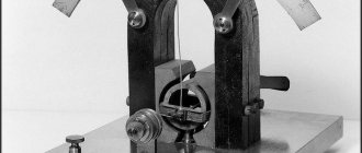
Current clamps with dial indicator. Historically, this is the first meter to use a transformer for alternating voltage. Such a system includes a varying number of turns included in the secondary part of the circuit.
According to the principle of operation, current clamps are divided into clamps for direct and alternating current. DC clamps are not suitable for measurements on circuits and lines with alternating voltage. With “variable” clamps the opposite is true - they are equally well suited for direct and alternating current.
For example, current clamps, classified as professional, allow you to work not only with high voltages up to 1 kV, but are also equipped with the functions of a megohmmeter, which allows you to measure the insulation resistance of wires. The ohmmeter has an impressive measurement range - from 20 MOhm. The multimeter is placed in a rubberized case with shockproof inserts that protect it from damage if accidentally dropped from a height of up to 10 m, which allows you to quickly return to work from the place where the incident occurred. This is, for example, the DT-360 model.
High-power current clamps are designed for significant currents - up to hundreds and even thousands of amperes. They, for example, are capable of withstanding a powerful impulse of starting current at the moment of starting a three-phase elevator motor in the entrance, and the automatic hold function ("Hold" mode) at the moment of sudden surges in current and voltage will show the "peak" of such an impulse in amperes (and voltage, at this moment “sagging” in voltage). Some models are also equipped with a watt/varmeter function, which partially replaces the electricity consumption meter for contactless monitoring of power lines approaching the building.
If the current clamp has a multimeter, which has the ability to record readings during fluctuations in current and voltage, measured reactive power in a system log, then such a device is a contribution to the process of self-diagnosis of possible faults in a line or electrical network. Such a device, in addition to the processor, ADC, RAM and ROM chip with microprogram, contains a chip for long-term data storage - flash memory.
For the convenience of transferring data to PCs and mobile devices and processing them using special applications, the device has a microUSB interface or wireless communication via Wi-Fi or Bluetooth. But such additional comfort can cost 10 thousand rubles or more per device. For reliability, the microcircuits on the control board have protective shielding against interference. They are all securely removed, “decoupled” from the high-voltage part of the circuit, through the shunts of which high voltages of hundreds of volts pass.
All types and varieties of current clamps, both produced in Russia and imported from abroad, on the territory of the Russian Federation fall under the restrictions of GOST No. 8.366-79 “GSI. Digital ohmmeters. Methods and means of verification", MI-1202-86-GSI. This standard forms the basic requirements imposed on the production, testing and verification of all products that in one way or another combine digital ohmmeters and current clamps. For specific companies, for example, Fluke (USA), other GOSTs also apply, for example, 22261-94 and 14014-91. They apply to the verification and testing of multimeters, which also combine the functions of volt and ammeters.
Device
As mentioned earlier, the mechanism of operation of clamps is based on the principles of a transformer current, which consists of a primary (usually a bus or wire) and secondary windings. The meter is connected to the secondary winding, which must be located on a detachable magnetic circuit. The wire around which the clamps are closed creates an alternating magnetic field around it, invisible to the human eye, which is measured by the device.
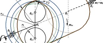
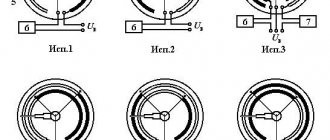
Based on the design, there are 2 types of current clamps: simple (a) - their operation is based on the operating principle of a single-turn transformer; complex (b) - they have a rectifier in their functionality, and their operation is also based on a single-turn transformer.
Device design
It is worth paying special attention to the picture diagram: it shows and marks the components of current clamps. So, number 1 on it directly indicates the wire that is being measured; number 2 - these are detachable cores (pincers); number 3 indicates the winding (secondary); number 4 is a built-in rectifier; number 5 is an image of a measuring frame; number 6 - drawing of the lacing resistance; number 7 indicates the toggle/mode switch; number 8 is the bracket (lever).
This diagram presented a very detailed internal structure of a clamp meter. However, it can be said that current clamps actually consist of three parts:
- Working: directly the clamps themselves and the magnetic circuit.
- Insulating: the space between the handle and the working part.
- Handle bodies.
You may be interested in: Features of a voltage comparator
Preparation for use
Work can be carried out on current-carrying elements both with and without insulation. Before use, electrical clamps must be carefully inspected for any defects, after which the handle and insulating element must be wiped with a clean, dry cloth. Also, during the inspection, you need to pay attention to the joints of the magnetic circuit parts: they should not show signs of corrosion or contamination, and the insulating part should have a uniform coating without visible damage. It is worth noting that rust particles on the magnetic circuit will reduce the tightness of its elements, and as a result, the measurement results will be incorrect. As stated earlier, dielectric gloves are an integral addition to the tool.
Where is it used?
Thanks to the wide range of modifications of current clamps on the market and in stores, they have become a very popular power tool and are used everywhere - from the average home to a huge construction site.
There are two main types of electric clamps: for measuring alternating current and for measuring direct current. The former, in fact, are a universal tool and are excellent for taking readings on lines and with constant voltage.
So, consider the following situation: Galina and Ivan Petrov began to notice that their electricity bills were getting higher and higher every month. They began to figure out how this was possible and came to the conclusion that perhaps one of their neighbors had connected to their network and was stealing electricity. Ivan went to the store and bought current pliers. Then, having previously turned off all electrical appliances in the apartment, the Petrovs, using clamps, measured the current in a separate phase conductor and recorded a reading above zero. This means that their suspicion turned out to be correct. Now all that remains is to find the location of the unauthorized connection.
As an example, we can give one more situation. Ivan Petrov has a car. But here's the problem: the battery began to discharge very quickly. However, he did not install any additional devices such as a car radio. This means there is a leak somewhere.
Using electric clamps in a car
To do this, pliers wrap around the positive wire coming from the battery. After this, you need to sequentially begin to remove fuses and turn off all kinds of electrical consumers until the cause of the leak is found.
Popular models
The difference in price may be due to both the use of a well-known brand and the materials used to manufacture the device. Let's look at the most popular current clamps on the Russian market.
Mastech 266
Mastech model M266
M266 current clamp
,
M266C
and
M266F
. The additional letters C and F in the model names indicate the ability to measure temperature and frequency. The models do not differ in shape, color and other parameters.
Country of origin: Hong Kong. All current clamps of the M266
measure:
- Alternating current - up to 1000 Amperes;
- AC and DC voltage - up to 1000 Volts;
- Resistance – up to 2 Mohm;
- Diode check
All models are supplied with high-quality electrical probes with good contact in the device. Convenient “Hold” button for recording readings on the screen under your thumb. Model cost:
M266 – 30$
;
М266С (with thermometer) – 31,50$
;
М266F (with frequency measurement) – 31,50$
.
Resanta DT 266
Resanta pliers DT 266
Chinese current clamps are of low quality and have a number of functional disadvantages:
- The probes quickly break at the junction of the cable and the plug.
- Poor dust protection of the device leads to contamination from inside the screen. If the device is used in dusty conditions, the screen becomes unreadable over time.
- Over time, play when opening the pliers leads to inaccurate connection of the jaws, and this leads to inaccuracies in measurements.
- There is no screen backlight. It is impossible to work in a room with poor lighting.
- The error of the device does not correspond to the declared one and is about 5%, which is unacceptable for such a multimeter.
- The response speed is very low compared to analogues. Voltage measurement lasts 2-5 seconds, current measurement lasts 6-8 seconds.
- Small symbols on the front panel of the device. It's difficult to make out what exactly is written. The paint with which the markings are applied is easily erased and after six months of work you can only switch from memory or by looking at the instructions
In general, the device is intended for use only in high voltage environments where high measurement accuracy is not necessary:
- Voltage DC/AC – 1000/750 volts;
- Connection testing;
- Resistance – up to 2Mohm
The undeniable advantage of this model is the price. 10,50$
, but considering that the service life of such a device will not exceed one year of active use, and during this time you will have to buy additional probes for it a couple of times, you will not get pleasure from using it.
How to use a clamp meter
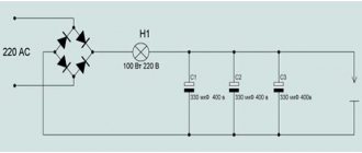
If you want to measure and find out the value of electricity consumed in 220 V networks (in an apartment, house), you can calculate it using the formula:
P = A ⋅ V ⋅ cosφ
where, cosφ = 1
Example: You need to measure the power consumption load of your apartment, house or some electrical appliance. We set the range switch to position ACA 200. Open the pliers and grasp one wire from the spirit (preferably phase). After a moment, the device will show some value, for example, 8 A.
Using the formula, we calculate the power consumption:
P = 8 ⋅ 220 ⋅ 1 = 1760 W = 1.76 kW
Current clamp meters are convenient, specialized devices that allow you to quickly and easily measure current. Most devices have a button that is responsible for recording the result. This makes it easier to work in tight spaces where it is impossible to constantly monitor the device display.
How to measure current
Measuring current in a circuit is not difficult: by pressing the lever, you need to open the clamps and pass the wire to be measured through them, and then record the measurement that appears on the screen.
First of all, you need to remember safety precautions. It is important that during the measurement there is no short circuit and no person gets electrocuted. Of course, for this purpose, the pliers themselves are covered with an insulating sheath. Therefore, you should not be afraid of electric shock, but you should also not forget that the device must be completely dry.
It is discussed above what electrical clamps are intended for. These devices are used to measure, usually alternating current, as quickly and accurately as possible. Depending on the design, this simple device can also serve as a thermometer or be used as a voltage or frequency sensor. In good hands, this device can become a real and irreplaceable weapon.
Classification
Such clamps can be classified according to the electrical measuring instrument used in them. In this capacity the following can be used:
- megohmmeters;
- ammeters;
- wattmeters;
- phase meters;
- ampere-voltmeters;
- multimeters.
High voltage current clamps
Of course, in everyday life the most common models are current clamps that are capable of measuring current up to 1 thousand volts. However, in industrial conditions there is often a need to study current parameters above 1000 V. It is for such situations that high-voltage current clamps were made. In essence, their design is no different from other models of these devices, but they have very high and reliable insulation to protect the person measuring from injury.
Current clamp with multimeter
This device is perhaps the most modern of all electrical appliances currently available on the market. This is like 3in1 coffee, only from the world of electricity! This small device contains a great variety of functions: in addition to basic current measurement, it is capable of obtaining data on voltage, capacitance, frequency, and resistance. In such devices, as a rule, the measurement error is minimal. They can measure current over very wide ranges. If there is a need to monitor the waveform, this device provides an analog output for connecting oscilloscopes.
Clamp multimeters
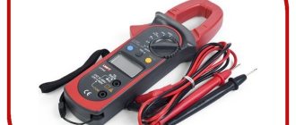
Digital current clamps
This device has a high degree of automation. This means that it is capable of determining the necessary modes itself depending on external conditions, as well as setting precise measurement limits. As a rule, they have a non-contact voltage tester and a convenient digital display with backlight function, and are manufactured in a reliable rubberized case.
Some of these devices are also capable, like the previous type, of receiving data on voltage, capacitance, frequency, resistance, temperature, duty cycle, checking diodes, and “testing” circuits. They have a “Data hold” function: you can save the obtained measurements after opening the clamps and keep a data log. They run on regular batteries and are very small in size and weight (about 200-300 grams). Ideal for electrical installation work.
Current clamps with dial indicator
Such electric pliers can rightfully be called the forefathers of all the subspecies described above. This device was the first to use the transformer principle to measure direct and alternating current. In them, instead of a convenient digital display, the data is displayed on a pointer mechanical panel, which is why they significantly lose in convenience and ease of use. However, they have a small measurement error, which is why they have not lost their popularity and competitiveness in the market in our age of digital devices.
Switch clamps
Safety precautions when working
Interaction with any devices that come into contact with electricity requires compliance with certain safety measures. The mites in question are no exception. During active actions carried out by them, it is prohibited:
- when connecting them to live elements, touch the open connectors;
- when working under voltage, measure resistance;
- switch ranges when the conductor is in the instrument;
- exceed the maximum overload capacity of the tool for a certain range.
With professional tools in electrical installations with voltages above 1000 V, work is carried out by 2 workers: 1 with group III and 1 with group IV.
Summing up
Current clamps are a must-have tool in any electrician's arsenal. Home craftsmen may not need them, but professionals should always have them on hand.
Sources
- https://OFaze.ru/teoriya/tokoizmeritelnye-kleshhi
- https://electrikagid.ru/instrument/elektroizmeritelnye-kleshhi.html
- https://YaElectrik.ru/elektroprovodka/tokoizmeritelnye-kleshhi
- https://ProFazu.ru/provodka/instruments/tokoizmeritelnye-kleshhi.html
- https://odinelectric.ru/wiring/tools/dlya-chego-prednaznacheny-tokoizmeritelnye-kleshhi
- https://rusenergetics.ru/instrumenty/dlya-chego-prednaznacheny-elektroizmeritelnye-kleschi
- https://stroyday.ru/stroitelstvo-doma/elektroxozyajstvo/kak-vybrat-tokovye-kleshhi-top-10-luchshix-tokoizmeritelnyx-kleshhej.html
- https://zen.yandex.com/media/asutpp.ru/tokovye-klesci—samyi-poleznyi-pribor-v-elektrike-hitrosti-i-sovety-5f2420f562983b4b06067964
[collapse]