Execution of the drawing is an important organizational part. The possibility of functioning of one part or an entire mechanism depends on the accuracy of the designations and correct composition. Therefore, for ease of reading, rules that are common to all have been developed to help correctly understand the project.
On technical drawings, it is sometimes necessary to note that a part has a beveled or rounded edge. This is necessary either for an aesthetically pleasing appearance or for more precise connection and performance of certain functions. This technical solution is called a chamfer.
The designation of a chamfer in a drawing depends on many subtleties - the number of bevels and their angle, the scale of the image, and the presence of other digital values.
In order to accurately manufacture an element that can perform the necessary functions, it is necessary not only to accurately draw the parts, but also to correctly mark their parameters so that the master can correctly manufacture the element.
Chamfer designation in the drawing
The dimensions of the chamfers in the drawing, at an angle of 45°, are marked with dimension lines or on the shelf of a leader line; if its size on the scale of the drawing is 1 mm or less, the chamfer is displayed as shown in the image below on the right side.
Designation of a chamfer on the drawing at an angle of 45°
Chamfers with an angle not equal to 45° are indicated by linear and angular dimensions or two linear dimensions.
Designation of a chamfer with an angle not equal to forty-five degrees
A chamfer is nothing more than an element of a part. The word chamfer owes its origin to the French word “ faccete ,” which means beveled parts of corners, edges, etc. The main part of chamfers is intended to blunt sharp corners in order to ensure the safety of subsequent technological operations or operation of products and mechanisms.
On technical drawings, chamfers and their geometric parameters are indicated in cases where it is necessary to clearly indicate its presence due to a technical solution. In other cases, chamfers or other edge shapes are not specified, but must be blunted .
Mainly, as mentioned above, chamfers are intended to ensure safety during further interaction between a person and the products of his production activities, but in some cases they are needed as decorative elements introduced by designers into the composition of the product.
Bevels are very often used in the woodworking industry. The presence of chamfers here, combined with roundings that turn into fillets and back, combine very well with flat surfaces and give the product a finished appearance. Even the presence of a simple chamfer on any part visually gives it volume, not to mention shaped chamfers with changing cutting trajectories and inclination angles.
When finishing mirrors, decorative chamfers are made along the edges, in the form of small bevels of the edges. These kinds of edges are obtained as a result of grinding with a special diamond tool, on machines designed for carrying out such types of work, with abundant cooling. Edges processed in this way are called “ beveled ”. When making doors, or any other parts of the interior, glazing elements are used in the form of small tiles of a given size with a bevel. In combination with noble wood, they create a composition that gives a special solemn look and an atmosphere of comfort.
There are chamfers with a fairly gentle bevel, which allow the parts to perform functions that ensure guaranteed engagement or engagement with the mating components of assemblies and mechanisms.
In internal combustion engines, gas timing is an important determining part of the operation of the system as a whole. To realize the conditions of gas exchange, the inlet and outlet openings must open and close strictly in a certain order and ensure effective gas exchange. The timely supply of the combustible mixture and the release of exhaust gases is carried out by valves, which are driven by the kinematic elements of the mechanisms. One of the components of the valve is the sealing chamfer; it is entrusted with the important function of guaranteed shutoff and ensuring the unhindered release of gases.
For high-quality metal welding, when connecting steel sheets exceeding the cross-sectional size of six or eight millimeters, technological chamfers are usually removed. There are two ways to prepare edges for welding - heat treatment or mechanical. Recently, edge preparation is most often used by the chipping method, in which the metal is displaced under the influence of tangential stresses. Such operations are performed by special machines with a system of guide rollers and a gripping round tool driven through a gearbox from an electric motor. The use of such mechanisms can significantly speed up preparatory work. The edge processing machine, "SNR - 12" from Spain, is an effective tool of this type.
Source
How to make a chamfer in AutoCAD by specifying the distance (length) and angle
Call the Chamfer command, then select the Angle option. The command line will display the following prompt:
First chamfer length <0.0000>:
Set its length in AutoCAD to 2 mm and press “Enter”. The system will issue a request:
Chamfer angle with first segment <0>:
Set the chamfer angle with the first segment at 45 degrees and press “Enter”. The program will repeat the request:
Select the first segment or [Cancel/PolyLine/Length/Angle/Cut/Method/Multiple]:
Let's select the first chamfer segment, which has been assigned a length and an angle (the side of the rectangle). The command line will display the following prompt:
Select the second line segment or press the Shift key while selecting to create an angle or [Distance/Angle/Method]:
When you hover the cursor over the second adjacent side of the rectangle, the program displays a preview of the chamfer. As soon as we indicate the second side of the rectangle, the chamfer will be built in AutoCAD , and the command will complete its execution.
Chamfer - manufacturing methods, designation on drawings, classification
You are familiar with the designation of scale (M), projection of a drawing: front, top, side views - you know the designation of diameter (0), radius (R) of a circle, metric thread (for example, M10, M6).
In working drawings, in addition to front, top, and side views, it may be necessary to show the internal shape of the part.
The internal shapes of the disk can be shown in views using dashed lines.
Disc image
a - in the figure; 6 - on drawing views.
The disk has three holes and four recesses. The front view has a lot of dashed lines, making it difficult to determine the internal shape of the part. To make the drawing more clear about the internal shapes of the part, sections and sections are used.
Sections
If, during a conditional section of an object, only that part of it that is in the secant plane is left, a section is obtained in its drawing sense.
Sections are divided into:
- being part of the cut;
- independent.
Among the independent ones there are:
- Taken out. They are drawn behind the outline of the main view. They are recommended by the standard as preferred.
- Overlaid. Placed directly on the drawing of the corresponding type or in its gap. Sometimes the design document becomes difficult to read.
Superimposed sections
The system of location, designation and naming of sections is similar to the system of designation of sections
It is important to remember that lines indicating sections cannot intersect with drawing elements. The secant trace is displayed as a thick line with a break
Basic provisions
Even small bevels of sharp edges present in the project must be indicated in the technical documentation if such smoothing has a functional significance. However, this is often not necessary, since according to ESKD (Unified System of Design Documentation) all sharp edges formed as a result of manufacturing and in contact with a person must be dulled. Depending on the scale and features of the node, it is possible to show the chamfer in several ways.
Typically, a chamfer in a drawing is indicated using dimension lines; the use of contour or axial lines for this is prohibited by GOST standards.
The main criterion is the possibility of convenient reading, so that during manufacturing there is no doubt about which unit the parameter belongs to. In this case, two numerical values must be indicated: the first is the width of the bevel in mm, the second is the angle relative to the main axis of the entire mechanism or a separate element. When depicting symmetrical chamfers at the same angle on one part, it is possible to separately indicate the first value, and depict the second by the value of the obtuse angle that they form. A chamfer is often used to designate a chamfer in a drawing with two linear dimensions, each of which indicates the size of the cut in different planes.
The image of a bevel, which in this scale is less than 1 mm, can be performed with an arrow with an extension shelf. Most often, both angular and linear dimensions are indicated.
The designation of a chamfer in a drawing in accordance with GOST is made in a standard font and only in one view; duplication in other projections is not required. In this case, the dimensions of the external chamfers are applied on the main side, and the internal ones are indicated only on the section.
Detail elements
If part of a detail drawing needs to be displayed in more detail than the selected scale of the main drawing allows, so-called callout elements are used.
The location of the extension element in the main view is indicated by a closed contour, most often round or oval. From there there is a thin arrow leading to the placement of a detailed image. If such a line is not drawn, the letter designation of the element is written above the extension line, and the letter is repeated above the detailed drawing.
Sometimes the callout element may differ from the type of the main image. Display in the form of sections, cuts, etc. is allowed.
The location of the extension element indicates detailed linear and angular dimensions, information about accuracy, quality and roughness, as well as other necessary information.
Applying dimensions
The standard and most often used are roundings made at an angle of 45 degrees. Therefore, if the exact value is not shown in the drawing, this particular slope is implied. Otherwise, when a different angle, such as 30 degrees, is to be used, a similar feature must be specified. This can be done in the same ways - using an extension line, as well as using linear dimensional symbols.
The presence in the drawing of 2 chamfers, which are located symmetrically and at the same diameter, requires indicating their size without additional notes. But if the application diameter is different (for example, the object is a cone or cylinders of different radii), it is necessary to indicate their exact number. It is worth considering that the bevels on the internal and external surfaces are summed up separately, even when their values are the same. In the case where the part has a regularly varying diameter, it is possible to use breaks so as not to complicate the drawing. In this case, the chamfer dimensions are drawn in the usual way; only the wavy line is taken into account, which cannot be used functionally, since it determines the missing distance.
The most difficult process seems to be the process of arranging the size of the chamfers at a small distance from each other, since in this case the drawing may turn out to be too congested.
The following solution is possible: the same parameters for all are indicated in the description under a digital designation (1, 2, 3, etc.), and only the reference number in the description is transferred directly to the drawing. As a result, there is no need to set the size in each individual case. However, it is worth remembering that an identical value that appears in other places must be denoted by the same number, even if it refers to a different page.
In many industries, for processing wood, steel and other materials, machine complexes are used, into which drawings are automatically stored. In these cases, to ensure safety and better contact with adjacent components and parts, chamfers are provided in advance. Depending on the type of production, thermal or mechanical effects are possible, which cannot be replaced by manual labor. Therefore, it is extremely important to carry out the technical drawing thoughtfully, not forgetting to indicate the exact numerical designations of the chamfers, as well as their number.
If you find an error, please select a piece of text and press Ctrl+Enter.
GOST 2.307-68 ESKD. Drawing dimensions and maximum deviations
STATE STANDARD OF THE USSR UNION
Unified system of design documentation
APPLICATION OF DIMENSIONS AND LIMIT DEVIATIONS
GOST 2.307-68 (ST SEV 1976-79, ST SEV 2180-80)
STATE STANDARD OF THE USSR UNION
| Unified system of design documentation APPLICATION OF DIMENSIONS AND LIMIT DEVIATIONS Unified system for design documentation. Drawing of dimensions and limit deviations | GOST 2.307-68 (ST SEV 1976-79, ST SEV 2180-80 |
Date of introduction 01/01/71
This standard establishes the rules for drawing dimensions and maximum deviations on drawings and other technical documents for products from all sectors of industry and construction.
(Changed edition, Amendment No. 3).
1.1. The basis for determining the size of the depicted product and its elements are the dimensional numbers printed on the drawing.
The exception is the cases provided for in GOST 2.414-75; GOST 2.417-78; GOST 2.419-68, when the size of a product or its elements is determined from images made with a sufficient degree of accuracy.
The basis for determining the required accuracy of a product during manufacturing is the maximum dimensional deviations indicated in the drawing, as well as the maximum deviations of the shape and location of surfaces.
1.2. The total number of dimensions in the drawing should be minimal, but sufficient for the manufacture and control of the product.
1.3. Dimensions that cannot be made according to this drawing and are indicated for greater convenience in using the drawing are called reference.
1.4. Reference dimensions are on the drawing, and in the technical requirements they write: “* Dimensions for reference.” If all the dimensions in the drawing are for reference, they are not marked with the “*” sign, but in the technical requirements they write: “Dimensions for reference.”
On construction drawings, reference dimensions are noted and specified only in cases provided for in the relevant documents approved in the prescribed manner.
1.5. The following sizes are referenced:
a) one of the sizes of a closed dimensional chain. Maximum deviations of such dimensions are not indicated in the drawing (Fig. 1);
___________
*Dimensions for reference.
Crap. 1
b) dimensions transferred from the drawings of blank products (Fig. 2);
___________
*Dimensions for reference.
Crap. 2
c) dimensions that determine the position of the elements of the part to be processed on another part (Fig. 3);
___________
1* Dimensions for reference.
2** Process on the mating part (or on the part...).
Crap. 3
d) dimensions on the assembly drawing, which determine the limiting positions of individual structural elements, for example, piston stroke, valve rod stroke of an internal combustion engine, etc.;
e) dimensions on the assembly drawing, transferred from the drawings of parts and used as installation and connecting ones;
f) overall dimensions on the assembly drawing, transferred from the drawings of parts or being the sum of the dimensions of several parts:
g) dimensions of parts (elements) made of long, shaped, sheet and other rolled products, if they are fully determined by the designation of the material given in column 3 of the main inscription.
Notes:
1. The reference dimensions specified in subparagraphs b, c, d, f, g of this paragraph may be applied both with maximum deviations and without them
2. Installation and connecting dimensions are dimensions that determine the dimensions of the elements by which this product is installed at the installation site or connected to another product.
3. Dimensions are dimensions that determine the maximum external (or internal) outline of the product.
1.6. On the drawings of products in sizes that are technically difficult to control; put the “*” sign, and in the technical requirements the inscription “Provision dimensions” is placed. instr."
Note. This inscription means that the execution of the size specified in the drawing with a maximum deviation must be guaranteed by the size of the tool or the corresponding technological process.
In this case, the dimensions of the tool or the technological process are checked periodically during the manufacturing process of products.
The frequency of monitoring of a tool or technological process is established by the manufacturer together with the customer’s representative.
1.7. It is not allowed to repeat the dimensions of the same element in different images, technical requirements, title block and specifications. The exception is the reference dimensions given in paragraph 1.5 b and g.
If in the technical requirements it is necessary to give reference to the size marked on the image, then this size or the corresponding element is indicated by a letter, and in the technical requirements an entry similar to that shown in the drawing is placed. 4.
___________
1. Parallelism tolerance of the hole axes. A
and
B
0.05 mm.
2. Size difference B
on both sides no more than 0.1 mm.
Crap. 4
Dimensions may be repeated on construction drawings.
1.5-1.7. (Changed edition, Amendment No. 2).
1.8. Linear dimensions and their maximum deviations in drawings and specifications are indicated in millimeters, without indicating a unit of measurement.
For dimensions and maximum deviations given in the technical requirements and explanatory notes on the drawing field, units of measurement must be indicated.
(Changed edition, Amendment No. 3).
1.9. If the dimensions in the drawing must be indicated not in millimeters, but in other units of measurement (centimeters, meters, etc.), then the corresponding dimensional numbers are written down with the designation of the unit of measurement (cm, m) or indicated in the technical requirements.
In these cases, units of measurement may not be indicated on construction drawings if they are specified in the relevant documents approved in the prescribed manner
1.10. Angular dimensions and maximum deviations of angular dimensions are indicated in degrees, minutes and seconds with the designation of the unit of measurement, for example - 4°; 4°30 ‘
; 12°45
‘
30
«
; 0°30
‘
40
«
; 0 ° 18
‘
; 0 ° 5
‘
25
«
; 0°0
‘
30
«
; 30°±l°; 30°±10
‘
.
Crap. 5
Crap. 6
1.11. For dimensional numbers, simple fractions are not allowed, with the exception of sizes in inches.
1.12. The dimensions that determine the location of the mating surfaces are set, as a rule, from the structural bases, taking into account the possibilities of making and controlling these dimensions.
1.13. When the elements of an object (holes, grooves, teeth, etc.) are located on the same axis or on the same circle, the dimensions that determine their relative position are applied in the following ways:
from the common base (surface, axis) - according to the line. 5a and b;
setting the sizes of several groups of elements from several common bases - according to the drawing. 5c;
setting the dimensions between adjacent elements (chain) - according to the drawing. 6.
1.14. Dimensions on drawings are not allowed to be drawn in the form of a closed chain, except in cases where one of the dimensions is indicated as a reference (see Drawing 1).
On construction drawings, dimensions are applied in the form of a closed circuit, except for cases provided for in the relevant documents approved in the prescribed manner.
The dimensions that determine the position of symmetrically located surfaces of symmetrical products are applied as shown in Fig. 7 and 8.
Crap. 7
___________
*Dimensions for reference.
Crap. 8
(Changed edition, Amendment No. 2).
1.15. For all dimensions marked on the working drawings, maximum deviations are indicated.
It is allowed not to indicate maximum deviations:
a) for dimensions that define zones of different roughness of the same surface, zones of heat treatment, coating, finishing, knurling, notches, as well as the diameters of knurled and notched surfaces. In these cases, the sign “” is applied directly to such dimensions;
b) for the dimensions of parts of individually produced products specified with an allowance for fit.
On such drawings, the “*” sign is placed in close proximity to the indicated dimensions, and in the technical requirements the following is indicated:
“* Dimensions with allowance for fit up to detail. . . . . ",
“* Dimensions with allowance for fit according to drawing. . . . . ",
“* Dimensions with allowance for fit, according to the mating part.”
On construction drawings, maximum dimensional deviations are indicated only in cases provided for in the relevant documents approved in the prescribed manner.
1.16. When making working drawings of parts manufactured by casting, stamping, forging or rolling with subsequent machining of part of the surface of the part, indicate no more than one size in each coordinate direction, connecting the machined surfaces with surfaces not subject to machining (Fig. 9 and 10) .
Crap. 9
Crap. 10
(Changed edition, Amendment No. 2).
1.17. If an element is depicted at a deviation from the image scale, then the size number should be emphasized (Fig. 10a).
Crap. 10a
(Introduced additionally, Amendment No. 2).
2.1. Dimensions in the drawings are indicated by dimensional numbers and dimension lines.
2.2. When applying the size of a straight segment, the dimension line is drawn parallel to this segment, and extension lines are drawn perpendicular to the dimension lines (Fig. 11).
Crap. eleven
2.3. When applying the size of an angle, the dimension line is drawn in the form of an arc with the center at its vertex, and the extension lines are drawn radially (Fig. 12).
Crap. 12
2.4. When applying the size of a circular arc, the dimension line is drawn concentrically to the arc, and the extension lines are parallel to the bisector of the angle, and the sign “Ç” is placed above the dimension number (Fig. 13).
Crap. 13
It is allowed to place extension lines of the arc size radially, and if there are also concentric arcs, it is necessary to indicate which arc the size belongs to (Fig. 14).
Crap. 14
2.4a. When drawing dimensions of parts similar to those shown in Fig. 14a, dimension lines should be drawn in the radial direction, and extension lines should be drawn along circular arcs (Fig. 14a).
Crap. 14a
(Introduced additionally, Amendment No. 2).
2.5. The dimension line at both ends is limited by arrows resting on the corresponding lines, except for the cases given in paragraphs. 2.16, 2.17, 2.20 and 2.21, and when drawing a radius line limited by an arrow on the side of the defined arc or fillet.
In construction drawings, instead of arrows, it is allowed to use serifs at the intersection of dimension and extension lines, and the dimension lines must protrude beyond the outer extension lines by 1 . . . 3 mm.
2.6. In the cases shown in Fig. 15, the dimension and extension lines are drawn so that they, together with the measured segment, form a parallelogram.
Crap. 15
2.7. It is allowed to draw dimension lines directly to the lines of the visible contour, axial, center and other lines (Fig. 16 and 17).
Crap. 16
Crap. 17
2.8. It is preferable to apply dimension lines outside the outline of the image.
2.9. Extension lines should extend beyond the ends of the dimension line arrows by 1. . 5 mm.
2.10. The minimum distances between parallel dimension lines should be 7 mm, and between the dimension and contour lines - 10 mm and are selected depending on the size of the image and the saturation of the drawing.
(Changed edition, Amendment No. 2).
2.11. It is necessary to avoid intersections of dimension and extension lines (see Figure 16).
2.12. It is not allowed to use contour lines, axial, center and extension lines as dimension lines.
2.13. Extension lines are drawn from the lines of the visible contour, except for the cases specified in paragraphs. 2.14 and 2.15, and cases when, when drawing dimensions on an invisible contour, there is no need to draw an additional image.
2.14. The contour dimensions of the curved profile are applied as shown in Fig. 16 and 17.
2.15. If it is necessary to show the coordinates of the vertex of the rounded corner or the center of the rounding arc, then extension lines are drawn from the point of intersection of the sides of the rounded corner or the center of the rounding arc (Fig. 18).
Crap. 18
2.16. If a view or section of a symmetrical object or individual symmetrically located elements is depicted only up to the axis of symmetry or with a break, then the dimension lines related to these elements are drawn with a break, and the break of the dimension line is made further than the axis or break line of the object (Fig. 19).
Crap. 19
In construction drawings in such cases, all dimensions may be indicated only up to the axis of symmetry, and the dimension lines at the intersection with the axis of symmetry may be limited by a serif cross.
2.17. Dimension lines may be drawn with breaks in the following cases:
a) when indicating the size of the diameter of a circle, regardless of whether the circle is depicted completely or partially, while the break of the dimension line is made further than the center of the circle (Fig. 20);
Crap. 20
b) when drawing dimensions from a base not shown in this drawing (Fig. 21).
Crap. 21
2.18. When depicting a product with a gap, the dimension line is not interrupted (Fig. 22).
Crap. 22
2.19. The values of the elements of the dimension line arrows are selected depending on the thickness of the lines of the visible contour and they are drawn approximately the same throughout the entire drawing. The shape of the arrow and the approximate relationship of its elements are shown in Fig. 23.
Crap. 23
(Changed edition, Amendment No. 2).
2.20. If the length of the dimension line is not sufficient to place arrows on it, then the dimension line is continued beyond the extension lines (or, accordingly, beyond the contour, axial, center, etc.) and the arrows are drawn as shown in Fig. 24.
Crap. 24
2.21. If there is not enough space for arrows on dimension lines arranged in a chain, the arrows can be replaced with serifs applied at an angle of 45° to the dimension lines (Fig. 25), or clearly marked dots (Fig. 26).
Crap. 25
Crap. 26
2.22. If there is not enough space for the arrow due to a closely located contour or extension line, the latter can be interrupted (Fig. 24 and 27).
Crap. 27
2.23. Dimensional numbers are applied above the dimension line, as close as possible to its middle (Fig. 28).
Crap. 28
2.24. When applying a diameter size inside a circle, the dimensional numbers are shifted relative to the middle of the dimensional lines.
2.25. When drawing several parallel or concentric dimension lines at a short distance from each other, it is recommended to place the dimension numbers above them in a checkerboard pattern (Fig. 29).
Crap. 29
2.26. Dimensional numbers of linear dimensions with different inclinations of dimension lines are placed as shown in figure 30.
Crap. thirty
If it is necessary to apply a size in the shaded area, the corresponding size number is applied on the shelf of the leader line (Fig. 31).
Crap. 31
2.27. Angular dimensions are applied as shown in Fig. 32. In the area located above the horizontal center line, dimensional numbers are placed above the dimensional lines on the side of their convexity; in the area located below the horizontal center line - from the side of the concavity of the dimension lines. It is not recommended to apply dimensional numbers in the shaded area. In this case, the dimensional numbers are indicated on horizontally applied shelves.
Crap. 32
For small corners with a lack of space, dimensional numbers are placed on the shelves of leader lines in any zone (Fig. 33).
Crap. 33
2.28. On construction drawings, it is allowed to apply linear and angular dimensional numbers and inscriptions without shelves of leader lines.
2.29. If there is not enough space above the dimension line to write the size number, then the dimensions are applied as shown in Fig. 34; if there is not enough space to apply the arrows, then they are applied as shown in the diagram. 35.
Crap. 34
Crap. 36
The method of applying the dimensional number at different positions of the dimensional lines (arrows) in the drawing is determined by the greatest ease of reading.
2.30. Dimensional numbers and maximum deviations are not allowed to be divided or crossed by any drawing lines. It is not allowed to break the contour line to apply the dimensional number and apply dimensional numbers at the intersection of dimensional, center or center lines. At the place where the dimension number is applied, the axial, center and hatch lines are interrupted (Fig. 36 and 37).
Crap. 36
Crap. 37
2.29, 2.30. (Changed edition, Amendment No. 2).
2.31. It is recommended to group dimensions related to the same structural element (groove, protrusion, hole, etc.) in one place, placing them in the image in which the geometric shape of this element is shown most fully (Fig. 38).
Crap. 38
2.32. When applying a radius size, place a capital letter R
.
2.33. If, when drawing the size of the radius of an arc of a circle, it is necessary to indicate the size that determines the position of its center, then the latter is depicted as the intersection of center or extension lines.
If the radius is large, the center can be brought closer to the arc; in this case, the radius dimension line is shown with a bend at an angle of 90 ° (Fig. 39).
Crap. 39
2.34. If it is not necessary to indicate the dimensions that determine the position of the center of the circular arc, then the radius dimension line may not be brought to the center and may be shifted relative to the center (Fig. 40).
Crap. 40
2.35. When drawing several radii from one center, the dimension lines of any two radii are not placed on the same straight line (Fig. 41).
crap. 41
If the centers of several radii coincide, their dimension lines may not be brought to the center, except for the extreme ones (Fig. 41a).
Crap. 41 a
2.36. The dimensions of the outer rounding radii are applied as shown in Fig. 42, internal fillets - to hell. 43.
Crap. 42
Crap. 43
Rounding radii, the size of which on the drawing scale is 1 mm or less, are not shown in the drawing and their dimensions are indicated as shown in Fig. 43a.
Crap. 43a
The method of applying dimensional numbers at different positions of dimensional lines (arrows) in the drawing is determined by the greatest ease of reading. Dimensions of identical radii may be indicated on a common shelf, as shown in Fig. 43b:
Crap. 43b
If the radii of fillets, bends, etc. are the same throughout the entire drawing or one radius is predominant, then instead of plotting the dimensions of these radii directly on the image, it is recommended to make an entry in the technical requirements like: “Fillet radii 4 mm”; “Internal bend radii 10 mm”; “Unspecified radii 8 mm”, etc.
2.35, 2.36. (Changed edition, Amendment No. 2).
2.37. When indicating the diameter size (in all cases), the sign “Æ” is placed before the size number.
2.38. Before the dimensional number of the diameter (radius) of the sphere, the sign Æ ( R
) without the inscription “Sphere” (Fig. 44). If it is difficult to distinguish a sphere from other surfaces in a drawing, then the word “Sphere” or the sign O can be written before the dimension number of the diameter (radius), for example, “Sphere Æ 18, OR12”.
The diameter of the sphere sign is equal to the size of the dimensional numbers in the drawing.
Crap. 44
2.39. The dimensions of the square are applied as shown in Fig. 45, 46 and 46a.
Crap. 45
Crap. 46
Crap. 46a
The height of the □ sign must be equal to the height of the dimensional numbers on the drawing.
2.38, 2.39 (Changed edition, Amendment No. 2).
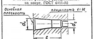
2.40. Before the dimensional number characterizing the taper, the sign “<” is applied, the acute angle of which should be directed towards the apex of the cone (Fig. 47).
Crap. 47
The cone sign and taper as a ratio should be marked above the center line or on the shelf of the leader line.
2.41. The surface slope should be indicated directly next to the image of the slope surface or on the shelf of the leader line in the form of a ratio (Fig. 48a), as a percentage (Fig. 48b) or in ppm (Fig. 48c). Before the dimensional number that determines the slope, a “<” sign is applied, the acute angle of which should be directed towards the slope.
Crap. 48
2.42. Markings of levels (height, depth) of a structure or its element from any reference level, taken as “zero” in the view and section, are placed on extension lines (or on contour lines) and are indicated by the sign “¯” made by solid thin lines, the length of the strokes is 2 - 4 mm at an angle of 45° to the extension line or contour line (Fig. 49a), in the top view they should be applied in a frame directly on the image or on the leader line (Fig. 49b), or as shown in Fig. 49a.
Crap. 49
Level marks are indicated in meters accurate to the third decimal place without indicating the unit of measurement.
2.43. The dimensions of the chamfers at an angle of 45° are applied as shown in Fig. 50.
Crap. 50
It is allowed to indicate the dimensions of a chamfer not shown in the drawing at an angle of 45°, the size of which in the drawing scale is 1 mm or less, on the shelf of a leader line drawn from the edge (Fig. 50a).
Crap. 50a
The dimensions of chamfers at other angles are indicated according to the general rules - linear and angular dimensions (Fig. 51a and b) or two linear dimensions (Fig. 51c).
Crap. 51
2.40-2.43. (Changed edition, Amendment No. 2).
2.44. The dimensions of several identical elements of the product, as a rule, are applied once, indicating the number of these elements on the shelf with a leader line (Fig. 52a).
It is allowed to indicate the number of elements, as shown in Fig. 52b.
Crap. 52
2.45. When applying the dimensions of elements evenly spaced around the circumference of the product (for example, holes), instead of the angular dimensions that determine the relative position of the elements, only their number is indicated (Fig. 53-55).
Crap. 53
Crap. 54
Crap. 55
2.46. The dimensions of two symmetrically located elements of the product (except for holes) are applied once without indicating their number, grouping, as a rule, all dimensions in one place (Fig. 56 and 57).
Crap. 56
___________
*Dimensions for reference.
Crap. 57
The number of identical holes is always indicated in full, and their sizes are indicated only once.
(Changed edition, Amendment No. 2).
2.47. When applying dimensions that determine the distance between evenly spaced identical elements of a product (for example, holes), it is recommended, instead of dimensional chains, to apply the size between adjacent elements and the size between extreme elements in the form of the product of the number of spaces between the elements and the size of the gap (Fig. 58).
Crap. 58
2.47a. It is allowed not to indicate on the drawing the dimensions of the radius of the arc of a circle of mating parallel lines (Fig. 58a).
Crap. 58a
(Introduced additionally, Amendment No. 2).
2.48. With a large number of dimensions applied from a common base, it is allowed to apply linear and angular dimensions, as shown in Fig. 59 and 60, while drawing a general dimension line from o and dimension numbers are applied in the direction of the extension lines at their ends.
Crap. 59
Crap. 60
2.48a. The dimensions of the diameters of a cylindrical product of complex configuration can be applied as shown in Fig. 60a.
Crap. 60a
(Introduced additionally, Amendment No. 2).
2.49. If there are a large number of similar elements of the product, unevenly located on the surface, it is allowed to indicate their dimensions in a summary table, using the coordinate method of drawing holes with their designation in Arabic numerals (Fig. 61), or designating similar elements in capital letters (Fig. 61a).
Crap. 61
Crap. 61 a
| Hole designation | Col. | Size, mm |
| A | 2 | 3 |
| B | 4 | 6,5 |
2.50. Identical elements located in different parts of the product (for example, holes) are considered as one element if there is no gap between them (Fig. 62a) or if these elements are connected by thin solid lines (Fig. 62b).
In the absence of these conditions, indicate the full number of elements (Fig. 62c).
Crap. 62
2.51. If identical elements of the product (for example, holes) are located on different surfaces and are shown in different images, then the number of these elements is recorded separately for each surface (Fig. 63).
Crap. 63
It is allowed to repeat the dimensions of identical elements of a product or their groups (including holes) lying on the same surface only if they are significantly removed from each other and are not related to each other in size (Fig. 64 and 65).
Crap. 64
Crap. 65
2.49-2.51. (Changed edition, Amendment No. 2).
2.52. If the drawing shows several groups of holes of similar sizes, it is recommended to mark the same holes with one of the symbols shown in the drawing. 66. It is allowed to use other symbols.
Crap. 66
The holes are indicated by symbols in the image, which shows the dimensions that determine the position of these holes.
On construction drawings, it is allowed to outline identical groups of holes with a solid thin line with an explanatory inscription.
2.53 When designating identical holes with conventional signs, the number of holes and their sizes may be indicated in the table (Figure 67).
Crap. 67
(Changed edition, Amendment No. 2).
2.54. When depicting a part in one projection, the size of its thickness or length is applied as shown in Fig. 68.
Crap. 68
2.55. The dimensions of a rectangular part or hole can be indicated on the leader line shelf by the dimensions of the sides through the multiplication sign. In this case, the size of the side of the rectangle from which the leader line is drawn should be indicated in the first place (Fig. 68a).
Crap. 68a
(Changed edition, Amendment No. 2).
3.1. Maximum dimensional deviations should be indicated immediately after the nominal dimensions. Maximum deviations of linear and angular dimensions of relatively low accuracy may not be indicated directly after the nominal dimensions, but may be specified by a general entry in the technical requirements of the drawing, provided that this entry unambiguously defines the values and signs of the maximum deviations.
A general record of maximum deviations of dimensions with unspecified tolerances must contain symbols of maximum deviations of linear dimensions in accordance with GOST 25346-89 (for deviations by qualifications) or in accordance with GOST 25670-83 (for deviations by accuracy classes). Symmetrical maximum deviations assigned according to qualifications should be indicated by indicating the qualification number.
Designations of one-sided maximum deviations by quality, assigned only for round holes and shafts (option 4 according to GOST 25670-83) are supplemented with a diameter sign (Æ).
Examples of general records corresponding to options in accordance with GOST 25670-83 for grade 14 and (or) accuracy class “medium” are given in table. 1:
Table 1
| Option number | Example of writing with symbols |
| 1. | N 14, |
| 2. | + t2, — t2 , |
| 3. | or |
| 4. | ÆN 14, Æ |
Notes:
1. It is allowed to supplement entries about unspecified maximum deviations of dimensions with explanatory words, for example, “Unspecified maximum deviations of dimensions: N
14,
h
14, ».
2. If the technical requirements in the drawing consist of one paragraph containing an entry about unspecified maximum dimensional deviations, or this entry is given in text documents, then it must be accompanied by explanatory words, for example, “Unspecified maximum dimensional deviations".
(Changed edition, Amendment No. 2).
3.la. Unspecified maximum deviations of radii of curvature, chamfers and angles are not specified separately, but must correspond to those given in GOST 25670-83 in accordance with the quality or accuracy class of unspecified maximum deviations of linear dimensions.
If all maximum deviations of linear dimensions are indicated immediately after the nominal dimensions (there is no general entry), then unspecified maximum deviations of the radii of roundings, chamfers and corners must correspond to those given in GOST 25670-83 for qualifications from 12 to 16 and are not specified in the drawing.
(Introduced additionally, Amendment No. 2).
3.2. Maximum deviations of linear dimensions are indicated in the drawings by symbols of tolerance fields in accordance with GOST 25346-89, for example: 18 N
7, 12
e
8 or numerical values, for example: 18+0.018, or symbols of tolerance fields indicating their numerical values on the right in parentheses, for example: 18
N
7(+0.018), 12
e
8.
It is allowed to indicate numerical values of maximum deviations in the table (Table 2), located on the free field of the drawing.
table 2
mm
| Size | Prev. off |
| 18N 7 | +0,018 |
| 12 e 8 | -0,032 -0,059 |
When indicating nominal dimensions with letter designations, tolerance fields must be indicated after a dash, for example, D
-H
11.
3.3. When indicating maximum deviations using symbols, it is also necessary to indicate their numerical values in the following cases:
a) when assigning maximum deviations (established by standards for tolerances and fits) of dimensions not included in the series of normal linear dimensions according to GOST 6636-69, for example: 41.5 18 N
7(+0,025),
b) when assigning maximum deviations, the symbols of which are not provided in GOST 25347-82, for example, for a plastic part with maximum deviations in accordance with GOST 25349-88 (Fig. 69);
Crap. 69
c) when assigning maximum deviations of the dimensions of ledges with an asymmetrical tolerance field (Fig. 70, 71);
Crap. 70
Crap. 71
d) (Deleted, Amendment No. 2).
3.4. Maximum deviations of angular dimensions are indicated only by numerical values (Fig. 72).
Crap. 72
3.5. When recording maximum deviations in numerical values, the upper deviations are placed above the lower ones. Maximum deviations equal to zero are not indicated, for example: ; ; 60+0.19; 60-0.19.
With a symmetrical arrangement of the tolerance field, the absolute value of the deviations is indicated once with a sign ±,
in this case, the height of the numbers defining the deviations must be equal to the height of the font of the nominal size, for example: 60±0.23.
3.6. Maximum deviations, indicated by numerical values expressed as a decimal fraction, are written down to the last significant digit inclusive, equalizing the number of digits in the upper and lower deviations by adding zeros, for example: ;
3.7. The maximum deviations in the dimensions of the parts shown in the assembly drawing are indicated in one of the following ways:
a) in the form of a fraction, the numerator of which indicates the symbol of the hole tolerance field, and the denominator - the symbol of the shaft tolerance field, for example: 50 or 50 N
11/
h
11 (Fig
.
73a);
b) in the form of a fraction, the numerator of which indicates the numerical values of the maximum deviations of the hole, and the denominator - the numerical values of the maximum deviations of the shaft (Fig. 73b);
Crap. 73
b1) in the form of a fraction, in the numerator of which the symbol of the tolerance field of the hole is indicated, with its numerical value indicated on the right in parentheses, and in the denominator - the symbol of the tolerance field of the shaft, with its numerical value indicated on the right in parentheses (Fig. 73c);
c) in the form of a record in which the maximum deviations of only one of the mating parts are indicated. In this case, it is necessary to explain which part these deviations relate to (Fig. 74).
_____________
*Dimensions for reference.
crap. 74
3.8. When different maximum deviations are assigned for surface areas with the same nominal size, the boundary between them is drawn with a solid thin line, and the nominal size is indicated with the corresponding maximum deviations for each area separately (Fig. 75).
crap. 75
The boundary line between areas should not be drawn through the shaded part of the image (Fig. 75a).
Crap. 75a
3.2-3.8. (Changed edition, Amendment No. 2).
3.9. If it is necessary to limit fluctuations in the size of identical elements of one part within part of the tolerance field (Fig. 76a) or it is necessary to limit the amount of accumulated error in the distance between repeating elements (Fig. 76b), then these data are indicated in the technical requirements.
______________ Maximum distance deviations
* Size difference 0.1 mm. between any non-adjacent teeth
±0.1 mm.
Crap. 76
3.10. When it is necessary to indicate only one limiting size (the second is limited in the direction of increase or decrease by some condition), after the size number indicate max or min, respectively (Fig. 77).
It is also possible to indicate maximum dimensions on assembly drawings for gaps, interference, backlash, etc., for example: “The axial displacement of the cam must be maintained within 0.6-1.4 mm.”
Crap. 77
3.11. The maximum deviations of the location of the hole axes can be specified in two ways:
a) positional tolerances of the hole axes in accordance with the requirements of GOST 2.308-79;
b) maximum deviations of dimensions coordinating the axes (Fig. 78 - 80).
Crap. 78
1. Limit deviations of dimensions between the axes of any two holes. ±0.35 mm.
2. Displacement of axes from plane A
no more than 0.18 mm
Crap. 79
Maximum deviations of dimensions diagonally between the axes of any two holes. ±0.5 mm.
Damn 80
If the tolerances for the location of the axes are dependent, then after the maximum deviations of the dimensions coordinating the axes, the sign of the dependent tolerance M should be indicated
(Changed edition, Amendment No. 2).
INFORMATION DATA
1. DEVELOPED AND INTRODUCED by the Committee of Standards, Measures and Measuring Instruments under the Council of Ministers of the USSR
PERFORMERS
V. R. Verchenko, Yu. I. Stepanov, Ya. G. Starozhilets, B. Ya. Kabakov, L. V. Matveev, P. N. Kolkin, V. N. Vzorov, M. G. Aranovsky, E. M. Koliseyeva.
2. APPROVED AND ENTERED INTO EFFECT by the Decree of the Committee of Standards, Measures and Measuring Instruments under the Council of Ministers of the USSR in December 1967.
3. The standard fully complies with ST SEV 1976-79 and ST SEV 2180-80.
4. INSTEAD OF GOST 3458-59, GOST 9171-59, GOST 5292-60 regarding section.
III
5. REFERENCED REGULATIVE AND TECHNICAL DOCUMENTS
| Designation of the referenced technical document | Item number, listing |
| GOST 2.308-79 | 3.11, item a |
| GOST 2.414-75 | 1.1 |
| GOST 2.417-78 | 1.1 |
| GOST 2.419-68 | 1.1 |
| GOST 6636-69 | 3.3, item a |
| GOST 25346-89 | 3.1, 3.2 |
| GOST 25347-82 | 3.3, item b |
| GOST 25349-88 | 3.3, item b |
| GOST 25670-83 | 3.1, 3.1a |
6. REISSUE (December 1990) with Amendments 2, 3, approved in June 1983; Fast. 2650 dated June 22, 1983, September 1987 (IUS 9-83, 12-87).
CONTENT
| 1. Basic requirements. 1 2. Applying dimensions. 6 3. Drawing of maximum dimensional deviations. 22 |
DESIGNATION OF SURFACE ROUGHNESS
1.1. Surface roughness is indicated in the drawing for all product surfaces made according to this drawing, regardless of the methods of their formation, except for surfaces whose roughness is not determined by the design requirements.
1.2. The structure of the surface roughness designation is shown in Figure 1.
When a sign is used without specifying the parameter and processing method, it is depicted without a shelf.
To designate surface roughness, the method of processing of which is not established by the designer, a sign is used (Fig. 2a).
To indicate the surface roughness, which should be formed only by removing a layer of material, the sign is used (Fig. 2b).
To designate the surface roughness, which must be formed without removing a layer of material, a sign is used (Fig. 2c) indicating the value of the roughness parameter.
1.2, 1.3. (Changed edition, Amendment No. 2, 3).
1.5. The value of the roughness parameter according to GOST 2789-73 is indicated in the roughness designation after the corresponding symbol, for example: 0.4; 6.3; 0.63; 70; 0.032; 50.
Note. In example 70, the relative reference length of the profile = 70% is indicated at the profile cross-section level = 50%.
1.6. When specifying a range of values for a surface roughness parameter in the roughness designation, the limits of the parameter values are given, placing them in two lines, for example:
The top line gives the parameter value corresponding to a coarser roughness.
1.7. When specifying the nominal value of the surface roughness parameter in the designation, this value is given with maximum deviations in accordance with GOST 2789-73, for example:
; ; ; and so on.
1.5-1.7. (Changed edition, Amendment No. 2, 3).
1.8. When specifying two or more surface roughness parameters in the roughness designation, the parameter values are written from top to bottom in the following order (see Figure 3):
profile irregularity height parameter
profile roughness step parameter
relative reference length of profile
(Changed edition, Amendment No. 3).
1.10. Symbols for the direction of irregularities must correspond to those given in the table. Symbols for the direction of irregularities are shown in the drawing if necessary.
Source
General provisions
4.1. Tolerances of the shape and location of surfaces in graphic documents are indicated using symbols (graphic symbols) or text in the technical requirements in the absence of such symbols.
4.2. Graphic symbols (signs) to indicate the tolerance of shape and location of surfaces are given in the table.
The shapes and sizes of the signs are given in the Appendix.
Examples of specifying tolerances for the shape and location of surfaces are given in the annex and ISO 1101 [].
Table 1
| Type of admission | Sign |
| Shape tolerance | Straightness tolerance |
| Flatness tolerance | |
| Roundness tolerance | |
| Cylindricity tolerance | |
| Longitudinal profile tolerance | |
| Location tolerance | Parallel tolerance |
| Perpendicularity tolerance | |
| Tilt tolerance | |
| Alignment tolerance | |
| Symmetry tolerance | |
| Positional tolerance | |
| Axis intersection tolerance | |
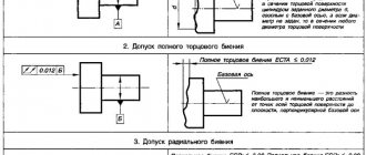
| Total tolerances of shape and location | Radial runout tolerance Axial runout tolerance Runout tolerance in a given direction |
| Tolerance for complete radial runout Tolerance for complete axial runout | |
| Shape tolerance of a given profile | |
| Shape tolerance of a given surface | |
| Note - Total tolerances of the shape and location of surfaces, for which separate graphic signs are not installed, are indicated by the signs of composite tolerances in the following sequence: location tolerance sign, shape tolerance sign. For example: – sign of the total tolerance of parallelism and flatness; - sign of the total tolerance of perpendicularity and flatness; – sign of the total tolerance of inclination and flatness. |
4.3. Tolerances of the shape and location of surfaces and their values in electronic models of products are indicated in the planes of designations and instructions in accordance with GOST 2.052.
4.4. Numerical values of tolerances for the shape and location of surfaces are in accordance with GOST 24643.
4.5. Tolerances of the shape and location of surfaces may be indicated in text in the technical requirements, as a rule, if there is no sign of the type of tolerance.
4.6. When specifying the tolerance of the shape and arrangement of surfaces in the technical requirements, the text must contain:
– type of admission;
– indication of the surface or other element for which the tolerance is specified (for this, use a letter designation or design name defining the surface);
– numerical value of the tolerance in millimeters;
– indication of the bases relative to which the tolerance is set (for location tolerances and total tolerances of shape and location);
– an indication of dependent tolerances of shape or location (in appropriate cases).
4.7. If it is necessary to standardize tolerances of shape and location that are not indicated in the graphic document by numerical values and are not limited by other tolerances of shape and location specified in the graphic document, the technical requirements must contain a general record of unspecified tolerances of shape and location with reference to GOST 30893.2.
For example:
“General tolerances of shape and location - according to GOST 30893.2 - K” or “GOST 30893.2 - K” (K - accuracy class of general tolerances of shape and location according to GOST 30893.2).
Preface
The goals, basic principles and general rules for carrying out work on interstate standardization are established by GOST 1.0 “Interstate standardization system. Basic provisions" and GOST 1.2 "Interstate standardization system. Interstate standards, rules and recommendations for interstate standardization. Rules for development, acceptance, updating and cancellation"
Standard information
1 DEVELOPED by the Federal State Unitary Enterprise "All-Russian Research Institute of Standardization and Certification in Mechanical Engineering" (FSUE "VNIINMASH"), the Autonomous Non-Profit Organization "Research Center for CALS Technologies "Applied Logistics" (ANO Research Center for CALS Technologies "Applied Logistics" )
2 INTRODUCED by the Federal Agency for Technical Regulation and Metrology
3 ADOPTED by the Interstate Council for Standardization, Metrology and Certification (protocol dated May 12, 2011 N 39)
The following voted for adoption:
Short name of the country according to MK (ISO 3166) 004-97
Abbreviated name of the national standardization body
Ministry of Economy of the Republic of Armenia
State Standard of the Republic of Belarus
Gosstandart of the Republic of Kazakhstan
4 By Order of the Federal Agency for Technical Regulation and Metrology dated August 3, 2011 N 211-st, the interstate standard GOST 2.307-2011 was put into effect as a national standard of the Russian Federation on January 1, 2012.
6 EDITION (July 2022) with Amendment (IUS 12-2012, IUS 10-2014, IUS 8-2018)
Information on the entry into force (termination) of this standard and amendments to it on the territory of the above states is published in the indexes of national standards published in these states, as well as on the Internet on the websites of the relevant national standardization bodies.
In case of revision, modification or cancellation of this standard, the relevant information will be published on the official website of the Interstate Council for Standardization, Metrology and Certification in the catalog “Interstate Standards”
An amendment has been made, published in IUS No. 1, 2022
Amendment made by database manufacturer
Useful lessons on similar topics and recommendations
Useful articles and video tutorials about chamfers in AutoCAD:
- bevel the edges of 2D objects in 3D space;
- how to make a chamfer in AutoCAD 3D.
Articles, video tutorials on specific topics:
- mating surfaces;
- connecting circles (practice);
- using the Fillet command in 3D space;
Read and watch also AutoCAD video tutorials:
- dimensions (types, placement, settings);
- picture (background);
- how to work in the program;
- editing objects;
- frame, main inscription of the drawing.
Courses, tutorials on AutoCAD:
- AutoCAD lessons (2D design).
- AutoCAD lessons (3D modeling).
- Descriptive geometry.
- Engineering graphics.
- House plan.
- Assembly drawing of a spur gear.
- 3D kitchen model.
Chamfer as a structural element of a part
Often during the manufacturing process of parts it becomes necessary to carry out additional processing of the internal and external edges. It is carried out at a given angle. The surface resulting from this processing is called a chamfer.
Chamfering is used to solve the following problems:
This treatment is used in many areas: mechanical engineering, in preparation for welding work, in the manufacture of furniture and interior decorative products. The choice of methods depends on the tasks assigned and always corresponds to the design documentation.
Cyclic mode of operation of the Chamfer command
The Chamfer command in AutoCAD can work in a cyclic mode. The “Multiple” command option is responsible for this mode. This option will allow you to continue creating a chamfer in AutoCAD after its first application.”
Advice
The program allows you to make chamfers even if the objects themselves do not intersect, but their extensions do. Objects are automatically completed and, if necessary, their ends are trimmed at chamfer points.
Mode for constructing chamfers in AutoCAD with trimming. Objects are automatically completed, their ends are trimmed at chamfer points.
Mode for creating a chamfer in AutoCAD without trimming. The chamfer is being built. Objects are not automatically completed and the ends are not trimmed at chamfer points.
Note
Using the AutoCAD Chamfer command is in many ways similar to using the Fillet command.
Why chamfering is necessary
Finishing the ends of parts, the edges of holes, the outside of bushings, and bolts is necessary to solve problems determined individually in certain types of processing.
In the manufacture of metal products:
Before carrying out welding work:
Chamfering in furniture production allows you to:
To select the necessary parameters, a special table has been developed that allows for the necessary processing.
Methods for creating a chamfer in AutoCAD
There are two ways to build it:
- “Length”—construct chamfers at two distances (available by default). Chamfer distances (lengths) are measured from the intersection point of two objects.
- “Angle”—creates chamfers along the length and angle.
Let's look at the methods for constructing chamfers in the program in more detail.
Chamfer angle
This parameter is determined by the design features of the manufactured part, assembly or assembly as a whole. The chamfer angle is determined by accepted standards and specifications. The value of this indicator depends on the selected material and the purpose of the specific structural element. For metal products, the state standard establishes the following values:
In accordance with the requirements of GOST, the possible value of the chamfer leg size is determined. The value of this parameter varies from 0.1 mm to 250 mm depending on the shape and size of the part.
For structures made of wood or synthetic materials, the angle values are determined by the requirements for a particular product. They are specified in the design documentation, where the minimum and maximum angle values and leg size are set.
Total tolerances of shape and location
Each of these parameters combines both permissible deviations. They arise as a result of the simultaneous manifestation of a change in geometric shape and the appearance of unevenness (roughness) of the treated surface. Therefore, using mathematical terminology, they say that the limit to which the difference between the standard and the real product should tend is considered the total tolerance of shape and location. The nature of the changes is determined by the method of comparison with the selected base objects. As such objects, proven structures or surfaces are chosen that can be considered standards, for example, various calibers.
Such tolerances are divided into the following categories:
- Beating. These include: radial, end, in a predetermined direction;
- All surface shapes.
Each of these categories has its own designation. The total runout tolerance is indicated by two oblique arrows in the form of vectors combined from below, directed from the lower left corner to the upper right. Comparison of shapes is made by combining both surfaces.
This field has specified geometric dimensions. It is oriented relative to the selected base so that the parallelism of the location can be checked. Examples of total tolerance indicate how much it is possible to change parameters without leading to rapid failure of the unit. This is especially true for mobile connections
Types of chamfers
This type of processing refers to the resulting surface shape. It is cut in several ways. These methods are designated by the Latin letters “Y”, “X” and “J”. In some literature and reference books on metalworking you can find other designations “V”, “K”, and “U”. These designations indicate the method for obtaining the required cut.
The most common are the first two methods. These types of chamfers are produced using standard metal-cutting tools on various processing machines: turning, milling, combined, CNC machines.
They also obtain chamfers for threads according to GOST. Currently, developed methods and equipment make it possible to obtain standard chamfer sizes.
In most cases, the procedure and rules for obtaining chamfers, geometric dimensions, and rules for drawing on drawings are determined by the established GOST 10549-80.
It sets valid values for the following parameters:
To obtain a more complex type of chamfer “J”, special chamfer removers are used. This type is most often used during preparatory work before welding. Thanks to this shape, a larger volume weld pool is obtained, which helps to obtain a stronger and higher-quality seam.
In some cases, other individual edge cutting forms are used. In this case, the procedure for their implementation is given in other standards or technical specifications. For example, Standard No. 5264 of 1980 provides rules for making a joint with a broken bevel.
Kinds
The preferred method for depicting three-dimensional products on a plane is orthogonal projection. The location of the depicted object is assumed to be between the conventional observer and the projection plane. To improve the readability of the image, a simplified approach is permitted. Therefore, the images in the drawings are not projection in the strict geometric sense of the word. They are called images on a plane. To obtain the main projections, the depicted part is placed in the center of an imaginary cube. Its edges will serve as projection planes.
Main types
As a result of the projection of the image of the object, a diagram of the main types of the product appears:
- front;
- on right;
- below;
- left;
- above;
- behind.
In technical drawing, the front view is considered the main one. It should give maximum information about the depicted detail. It is complemented by views from the left and from above (relative to the main one). These three types are called the main ones. The rest are considered auxiliary. Their images are constructed if important design information about a product of complex shape is not visible in the three main views.
In addition, to explain the structure of part of the part, local views are used, showing a fragment of the image of the main view. Such images are placed in unoccupied areas, inscribed in capital letters of the Cyrillic alphabet. On the main view, in the area where the fragment is located, there is an arrow showing the direction of the conditional view, as a result of which the local view appears. Such designs are limited by break lines drawn in the direction of the minimum element size.
In addition, additional types are used. They are built on planes placed at an angle to the main faces of the projection cube. They help to illustrate the location and structure of those parts of the object that are not visible or are not sufficiently presented in the main views, or their dimensions and configuration are distorted. The designation of additional species is carried out using letters of the Cyrillic alphabet.
Additional views
A thoughtful choice of local and additional views allows you to reduce the number of hatches when showing the internal structure of a part that is invisible on the main projections. The readability of the drawing, the relative position of its parts also improves, and the likelihood of its erroneous interpretation is reduced.
Manufacturing methods
The methods used to make edges depend on the following conditions:
According to the method used, the following types of edge preparation are distinguished:
To cut bevels on metal products, various metalworking equipment equipped with special tools is used. With its help you can obtain the required chamfer size for the thread. The use of special cutters and milling tools allows chamfering of holes.
Particular attention is paid to preparing the edges of the transition from one shaft diameter to another. This transition is called a fillet. It is quite common in mechanical engineering. The design of fillets with shafts is carried out in various ways in compliance with established standards.
As already noted, special chamfer removers are used for more accurate edge removal. They allow you to obtain a given angle and leg length.
How to set the chamfer size in KOMPAS
The chamfer size is a regular linear dimension, which can be set either by Auto Dimension or Linear Dimension.
The only thing that is often done is that the size is not placed on each chamfer, but the quantity with the same parameters is signed.
For example, like this:
The inscription “2 chamfers” is the text under the size inscription. To place it, you need to set the usual linear dimension, then double-click on the dimension label and enter the text here:
You can enter text from the keyboard, you can double-click in the text cell under the size label and select the appropriate option from the list provided
How to remove chamfers
To remove chamfers, there is a special command that allows you to restore the original geometry. The command is located on the Edit toolbar
After calling the command, just click on the created chamfer and it will be deleted. For example, it was like this
After using the command it looked like this:
Chamfer drawing according to GOST (ESKD)
A chamfer is a surface formed by a bevel of the end edge of a material.
The chamfer drawing is carried out on the basis of GOST 2.109-73 - a unified system of design documentation (ESKD).
You can download this simple drawing for free to use for any purpose. For example, for placement on a nameplate or sticker.
How to draw a drawing:
You can draw a drawing either on a sheet of paper or using specialized programs. No special engineering knowledge is required to complete simple sketch drawings.
A sketch drawing is a drawing made “by hand”, observing the approximate proportions of the depicted object and containing sufficient data for the manufacture of the product.
The design drawing with all the technological data for manufacturing can only be completed by a qualified engineer.
To designate in the drawing, you must perform the following operations:
1. Draw an image; 2. Add dimensions (see example); 3. Specify the technical requirements for manufacturing (read more about the technical requirements below in the article).
It is most convenient to draw on a computer. Subsequently, the drawing can be printed on paper using a printer or plotter. There are many specialized programs for drawing on a computer. Both paid and free.
Drawing example:
This image shows how simple and quickly drawing can be done using computer programs.