The lm393 chip is a double differentiated comparator from the manufacturer Texas Instruments. The device has a one-piece plastic body. Inside it there are 2 lm393 operational amplifiers, which are not connected to each other in any way. Their main task is to compare with each other all analog signals that arrive at their inputs.
The result of the operation of these elements is the appearance of an output voltage, or, conversely, its zero value.
This article is an overview of the microcircuit, its technical characteristics, the lm393 switching circuit and its operation using the example of a regular table lamp.
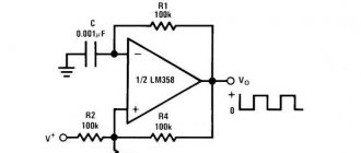
Lm393 square wave generator
Online generator calculator:
This circuit works similar to a Schmitt trigger. The comparator's reference voltage depends on its output voltage. The picture below shows the operating principle of a comparator-based generator.
[Output period]
| When V1 reaches +λ*VCC, the output switches to -VCC. The capacitor's capacitance charges to +λ*C*VCC and begins to discharge. |
The basic equation for determining the charge on a capacitor that had an initial charge is:
For this case, V = -VCC, and q0 = λ*C*VCC, so the following expression for the capacitor charge is obtained:
When charge q reaches the value λ*VCC, another switch will occur. The elapsed time will be half the period of the square wave, T/2. The reverse switching will occur at the lowest charge point:
The signal period can be calculated using the formula:
Note that although the expressions include the supply voltage VCC (the generator switches the output voltage from -VCC to +VCC), the switching period does not depend on its value. The frequency of the generator (the period of its signal T) can be changed using the values of the capacitance of the capacitor C and resistor R.
The comparator can be replaced with any operational amplifier.
[Usage example]
Using the LMV331 comparator, I assembled an automatic fire generator for the KEMPSTON joystick. The LMV331 comparator is made in a miniature 5-pin SC70 package, so the circuit easily fits into the joystick case.
The figure below shows a diagram of a generator for automatic fire. The 220 kOhm trimmer allows you to adjust the frequency of the generator in the range from 0.7 Hz to 36 Hz, which is quite sufficient (the maximum frequency with which a person usually presses the “Fire” button of the joystick is approximately 4 Hz).
Source
Principles for measuring robot rotation angle using the H206 sensor
There are many ways to determine the robot's rotation angle. Typically, accelerometers or gyroscopes are used for these purposes. But a cheaper method that we used in our project is to install H206 sensors on both wheels of the robot. This way we can find out how many revolutions each wheel made. The following figure shows the principle of calculating the robot's rotation angle according to this method.
When we first turn on power to the robot, it is assumed that its rotation angle is 0°. If the left wheel rotates, the angle increases in the negative direction, and if the right wheel rotates, the angle increases in the positive direction. To simplify understanding, consider the angle range from -90 to +90 as shown in the above figure. Since both wheels are the same diameter, if one wheel makes one full rotation, the robot will turn at an angle of 90°.
For example, if the left wheel makes a full rotation (80 interruptions), the robot will turn 90° to the left. Likewise, if the right wheel makes a full rotation (80 interrupts), the robot will turn -90° to the right. That is, if the Arduino board detects 80 interruptions from one wheel, then we can assume that the robot has turned 90° in the corresponding direction, so to calculate the rotation angles we can use the formula:
Arduino
| 1 2 | int angle_left = (left_intr % 360) * (90/80); int angle_right = (right_intr % 360) * (90/80); |
The 90 in this formula denotes the angle covered in 80 interruptions. We also use a radix 360 modulus so that the resulting value never exceeds 36. When we calculate the right and left rotation angles using the above formula, we can find the resulting rotation angle using the difference between these angles:
Arduino
| 1 | angle = angle_right — angle_left; |
Texas Instruments CD4001B CD40106B LM311 LM339-N LM393
Diagrams of simple devices are presented that allow you to adjust the width of signals taken from external pulse generators in the range from 0 to 100%
Digital signal width regulators are most often used in control circuits for the operation of converter equipment, various types of regulators, in D-class amplifiers, etc.
Classic regulators of the width of signals synthesized by pulse generators are quite well known and studied. Their disadvantages are also known, related to the fact that simultaneously with a change in the pulse duty cycle D, the generation frequency also changes. It would seem that it is more preferable to change the width of an already generated pulse signal from an external generator within specified limits. However, when analyzing available sources of patent and technical information, it was not possible to find such devices. Pulse expanders/compressors did not solve the problem.
| Picture 1. | Controller of the width of 0...100% pulses of an external generator on CMOS chips. | |
Figures 1-4 below show options for controlling the output signal width from 0 to 100%. To fully implement the control idea, it is desirable that the duty cycle of the input signal be close to 2, although some of the circuits allow for the possibility of maintaining the functionality of devices even with a significant deviation from the stated conditions. The second feature of control circuits is that they can operate in a limited frequency range of the input signal.
| Figure 2. | Pulse width regulator on the LM339 operational amplifier. | |
Figure 1 shows a variant of the circuit for smoothly controlling the width of 0...100% pulses taken from an external generator. The operation of the device is based on a dynamic comparison of voltage levels on the plates of capacitor C1 during periodic charge-discharge processes. Element DD1.1 is optional and is intended only to ensure stability of the pulse amplitude at its output. The device operates in the frequency range 10…200 kHz with a duty cycle of input pulses of 50%. A feature of the regulator circuits here and below is that with increasing frequency, an equal range of adjustment of the output pulse width from 0 to 100% is achieved in an increasingly narrow range of adjustment of the potentiometer slide (R2 - Figures 1, 2 or R3 - Figures 3, 4).
| Figure 3. | Pulse width regulator on the comparator LM311. | |
The second version of the pulse width regulator (Figure 2) is also based on a comparison of the voltages floating on the plates of capacitor C1.
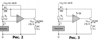
| Figure 4. | Balanced pulse width regulator on the LM393 comparator. | |
The next version of the pulse width regulator (Figure 3) uses a different construction scheme, although its operation is based on periodic charge-discharge processes of capacitor C1 and comparison of floating voltage levels using the DA1 LM311 comparator. To ensure steep edges of output pulses, an inverter based on the DD1.2 CD40106 element is designed.
| Figure 5. | Dynamics of transient processes at the inputs and output of the balanced pulse width regulator on the LM393 comparator. | |
The small collection of signal width regulators received from external pulse generators is completed by a balanced pulse width regulator made on the LM393 comparator (Figure 4). The device operates in the frequency range of input signals from 5 to 150 kHz. The dynamics of transient processes at the inputs and output of the balanced regulator when the regulator slider (potentiometer R3) is in its middle position is shown in Figure 5, which corresponds to a duty cycle of the output signal pulses of 50%.
Source
Speed sensor LM393 (H206)
The main role in our project is played by the LM393 speed sensor, so we will briefly consider its operating principle. The LM393 speed sensor (H206) consists of an integrated infrared sensor and an LM393 voltage comparator chip, which is why it is called the LM393 speed sensor. The sensor also includes a plate with a mesh graduation, which must be mounted on the rotating axis of the engine. The appearance of this sensor is shown in the following figure.
PWM on comparator LM393
Good afternoon Recently I became interested in digital circuitry and quietly switched to analogue. Why did this happen? While designing a dynamic display using discrete logic, the idea arose to implement PWM . The idea is interesting, but there was not much experience. Therefore, the idea immediately arose to install a microcontroller. But it's not that interesting, especially when the target is learning. And so, after some time, I came to the conclusion that it is possible to implement PWM on comparators .
The concept of PWM is that there is a sawtooth signal that goes to the input of the comparator and a signal from the voltage divider . And at the moment of intersection occurrence, a signal is set at the output of the comparator. The closer the voltage from the divider is to the peak of the saw, the shorter the time of the high signal and vice versa.
The task was to generate a sawtooth signal. To do this, I decided to assemble a relaxation generator on a comparator . But its peculiarity is that it has a small duty cycle (that is, 90-95% high level and 5-10% low). This is necessary so that the swing for PWM adjustment is almost full. Otherwise, only 50% will be available and no more (if the generator has a duty cycle of 50%). of the RC chain was used (resistor R2 sets the ratio of high and low levels).
And then using an integrating (RC) chain you need to make a saw. During testing, an idea arose, instead of a resistor in an RC circuit, to use a current source on two transistors. This was done to ensure uniform charging of the capacitor. And fast discharge occurs thanks to the diode.
Now that you have a ramp signal source , it will not be difficult to create a PWM signal . To do this, it is necessary to apply voltage from the divider to the inverting input of the comparator. But here a problem arises: a photoresistor . Its peculiarity is that in the light its resistance is about 1 kilo-ohm or several, and in the dark it reaches 2-3 mega-ohms.
Principles for measuring distance traveled using the H206 sensor
As we already know, in our project the Arduino board will detect 40 interrupts during a full revolution of the wheel. Obviously, the distance covered by the robot per revolution of the wheel will be equal to its circumference. Since we know the radius of the wheel, therefore, we can calculate the distance traveled using the following formula:
Arduino
| 1 2 | Distance = 2πr * number of rotations distance = (2*3.141*radius_of_wheel) * (left_intr/40) |
Power supply of powerful LEDs from 12 volts on the LM393 chip
The LM358 chip, as written in its DataSheet, is a universal solution, since the connection circuit of most popular devices is very simple, in cases where there are no strict requirements for high speed, power dissipation and non-standard supply voltage. Low cost, no need to connect additional frequency correction elements, the ability to use it over the entire range of standard supply voltages (up to +32V) and low current consumption make it the number one candidate for electronic projects with op-amps.
Input offset voltage and hysteresis
For most comparator circuits, the hysteresis value is the difference in input signal voltage at which the comparator output is either completely on or completely off. Hysteresis in comparators is generally undesirable, but it may be required when it is necessary to reduce sensitivity to noise or when the input signal is changing slowly.
External hysteresis uses positive feedback (POF) from the output to the non-inverting input of the comparator. The resulting Schmitt trigger provides additional noise immunity and a cleaner output signal.
The effect of using hysteresis is that as the input voltage changes gradually, the reference voltage will quickly change in the opposite direction. This ensures clean switching of the comparator output.
The mechanical analogue of hysteresis can be found in a variety of toggle switches. Once the toggle handle is moved past the center point, the spring in the toggle switch moves the relay contacts to the guaranteed position (open or closed).
Read also: Crimping 100 Mbit 4 cores
Hysteresis is an integral part of most comparators, amounting to only a few millivolts and it usually only affects circuits where the input voltage rises or falls very slowly or has voltage spikes known as "noise"...
Author: Sergey · Published 01/27/2017 · Updated 07/10/2019
The LM393 illumination module is used to measure light intensity in various devices, such as light automation (turning on lights at night), robots (detection of day or night) and devices that control light levels. Measurements are carried out using a photosensitive element (photoresistor), which changes resistance depending on the illumination.
Technical specifications
5.5 V ► Current consumption: 10 mA ► Digital output: TTL (log 1 or log 0) ► Analog output: 0 V ... Vcc ► Mounting hole diameter: 2.5 mm ► Output current: 15 mA ► Dimensions: 42mm x 15mm x 8mm
General information
There are two modules, visually the only difference is in the number of pins (3 pin and 4 pin), an additional pin has been added to take direct readings from the photoresistor (analog output), the article will discuss the four-pin version of the module. In these two modules, the measurement is carried out using a photoresistor, which changes the voltage in the circuit depending on the amount of light falling on it. To imagine how light will affect the photoresistor, I will give a short table.
The four-pin lighting module contains two output pins, analog and digital, and two power supply pins. To read the analog signal, a separate “AO” pin is provided, from which voltage readings can be read from 0 V ... 3.3 V or 5 V, depending on the power source used. Digital output DO, set to log “0” or log “1”, depending on the brightness, output sensitivity can be adjusted using a rotary potentiometer. The output current of the digital output is capable of delivering more than 15 mA, which greatly simplifies the use of the module and makes it possible to use it bypassing the Arduino controller and connecting it directly to the input of a single-pin relay or one of the inputs of a double-pin relay. The circuit diagram of the lighting module on LM393 with 3 pin and 4 pin is shown below.
Schematic diagram of the lighting module on LM393 with 4 pin
Schematic diagram of the lighting module on LM393 with 3 pin
Now how does the circuit work, the photoresistor is shown Foto (IN). The main chip of the modules is the comparator LM393 (U1), which compares the voltage levels at the INA- and INA+ inputs. The sensitivity of the response threshold is set using potentiometer R2 and as a result of comparisons at the output D0 of the U1 chip, a log “0” or log “2” is formed, which is sent to pin D0 of connector J1.
Circuit operation
The robot circuit based on Arduino and LM393 speed sensor is shown in the following figure.
Computational and control tasks in the circuit are assigned to the Arduino Nano board. The robot's wheels are driven by two DC motors using an L298N H-bridge motor driver. The joystick is used to control the speed and direction of the robot, and two H206 speed sensors are used to measure the speed, distance traveled and turning angle of the robot. The measured values of these parameters are displayed on a 16×2 LCD screen. A potentiometer connected to the LCD can be used to control its contrast, and a resistor serves to limit the current to control the brightness of the display's backlight.
The circuit is powered by a 7.4V lithium cell. This 7.4V is supplied to the 12V pin of the motor driver, and the motor driver voltage regulator converts it into a regulated +5V voltage, which is used to power the Arduino board, LCD, sensors and joystick.
The motors are controlled using digital pins 8, 9, 10 and 11 of the Arduino board. Since we also need to control the rotation speed of the motors, we use PWM (pulse width modulation) signals applied to the positive contacts of the motors. For this purpose, we use pins 9 and 10 of the Arduino board, which can use PWM signals. The position values of the joystick's X and Y axes are supplied to analog pins A2 and A3, respectively.
Because, as we already know, the H206 sensor generates a control action (trigger) every time a hole is detected in the division plate. To increase the accuracy of speed determination, we will apply these control actions to the external interrupt inputs on pins 2 and 3 of the Arduino board. After assembling the robot, we got the design shown in the following figure. You can see it in more detail in the video given at the end of the article.
Specifications
The following are the maximum permissible operating conditions for the ambient operating temperature range TA from 0 to +70 °C, unless otherwise stated.
Basic electrical characteristics, at ambient temperature TA = 25 °C.
Recommended operating conditions within the ambient operating temperature range unless otherwise noted:
Device susceptibility to electrostatic discharge (ESD) damage:
This device also has thermal characteristics:
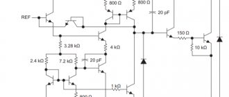
Description and application of the LM358 operational amplifier. Connection circuits, analogue, datasheet
LM358 chip contains two independent low-power operational amplifiers with high gain and frequency compensation in one package. Features low current consumption. A special feature of this amplifier is the ability to operate in circuits with unipolar power supply from 3 to 32 volts. The output is short-circuit protected.
Description of operational amplifier LM358
The scope of application is as an amplifier converter, in DC voltage conversion circuits, and in all standard circuits where operational amplifiers are used, both with unipolar and bipolar supply voltages.
LM358 Specifications
- Unipolar power: from 3 V to 32 V.
- Bipolar power supply: ± 1.5 to ± 16 V.
- Current consumption: 0.7 mA.
- Common mode input voltage: 3 mV.
- Differential input voltage: 32 V.
- Common mode input current: 20 nA.
- Differential input current: 2 nA.
- Differential voltage gain: 100 dB.
- Output voltage swing: 0 V to VCC - 1.5 V.
- Harmonic Distortion: 0.02%.
- Maximum output slew rate: 0.6 V/µs.
- Unity gain frequency (temperature compensated): 1.0 MHz.
- Maximum power dissipation: 830 mW.
- Operating temperature range: 0…70 degrees C.
Dimensions and pin assignments of LM358 (LM358N)
Analogs LM358
Below is a list of foreign and domestic analogues of the LM358 operational amplifier:
- GL358
- NE532
- OP221
- OP290
- OP295
- TA75358P
- UPC358C
- AN6561
- CA358E
- HA17904
- KR1040UD1 (domestic analogue)
- KR1053UD2 (domestic analogue)
- KR1401UD5 (domestic analogue)
Examples of application (connection circuit) of the LM358 amplifier
Simple non-inverting amplifier
Comparator with hysteresis
Let us assume that the potential supplied to the inverting input gradually increases. When its level reaches just above the reference (Vh -Vref), a high logic level will appear at the output of the comparator. If after this the input potential begins to slowly decrease, the comparator output will switch to a low logic level at a value slightly below the reference (Vref - Vl). In this example, the difference between (Vh -Vref) and (Vref – Vl) will be the hysteresis value.
Sine Wave Generator with Wien Bridge
Wien bridge oscillator is a type of electronic oscillator that generates sinusoidal waves. It can generate a wide range of frequencies. The generator is based on a bridge circuit originally developed by Max Wien in 1891. The classic Wien oscillator consists of four resistors and two capacitors. The oscillator can also be thought of as a forward amplifier combined with a bandpass filter that provides positive feedback.
Differential amplifier on LM358
The purpose of this circuit is to amplify the difference between two incoming signals, with each of them multiplied by a certain constant value.
A differential amplifier is a well-known electrical circuit used to amplify the voltage difference between 2 signals received at its inputs. In the theoretical model of a differential amplifier, the magnitude of the output signal does not depend on the magnitude of each individual input signal, but depends strictly on their difference.
Function generator
This function generator produces triangular and rectangular signals.
Square pulse generator on LM358
As an example of use, here is a microphone amplifier circuit based on LM358:
Datasheet LM35
Testing the robot's operation
Once the hardware for the project is ready, upload the program to the Arduino board. After this, pick up the joystick and try to control the robot - during this process, information about the speed, distance traveled and angle of rotation of the robot will be displayed on the LCD display screen.
On the LCD screen, the Lt and Rt values will represent the interrupt counters on the left and right, respectively. The values of these counters will be incremented each time a hole (missing) is detected in the speed sensor plate. The S parameter on the display screen will inform about the speed of the robot in m/s, and the D parameter will show the distance traveled in meters. When the robot is standing straight, its rotation angle will be displayed as 0°, when the robot is turned counterclockwise, the angle will become negative, and when the robot is turned clockwise, it will be positive.
You can watch all these processes in more detail in the video at the end of the article.
Description and application of the LM358 operational amplifier. Connection circuits, analogue, datasheet
LM358 chip contains two independent low-power operational amplifiers with high gain and frequency compensation in one package. Features low current consumption. A special feature of this amplifier is the ability to operate in circuits with unipolar power supply from 3 to 32 volts. The output is short-circuit protected.
Description of operational amplifier LM358
The scope of application is as an amplifier converter, in DC voltage conversion circuits, and in all standard circuits where operational amplifiers are used, both with unipolar and bipolar supply voltages.
LM358 Specifications
- Unipolar power: from 3 V to 32 V.
- Bipolar power supply: ± 1.5 to ± 16 V.
- Current consumption: 0.7 mA.
- Common mode input voltage: 3 mV.
- Differential input voltage: 32 V.
- Common mode input current: 20 nA.
- Differential input current: 2 nA.
- Differential voltage gain: 100 dB.
- Output voltage swing: 0 V to VCC - 1.5 V.
- Harmonic Distortion: 0.02%.
- Maximum output slew rate: 0.6 V/µs.
- Unity gain frequency (temperature compensated): 1.0 MHz.
- Maximum power dissipation: 830 mW.
- Operating temperature range: 0…70 degrees C.
Dimensions and pin assignments of LM358 (LM358N)
Analogs LM358
Below is a list of foreign and domestic analogues of the LM358 operational amplifier:
- GL358
- NE532
- OP221
- OP290
- OP295
- TA75358P
- UPC358C
- AN6561
- CA358E
- HA17904
- KR1040UD1 (domestic analogue)
- KR1053UD2 (domestic analogue)
- KR1401UD5 (domestic analogue)
Analogs
Analogues of LM358 can be considered microcircuits in which identical characteristics are indicated. These include: LM158, LM258, LM2904, LM2409. These microcircuits differ slightly from the one described in their thermal parameters and are suitable as a replacement for most projects.
To replace it you can use: GL 358, NE 532, OP 04, OP 221, OP 290, OP 295, OPA 2237, TA7 5358-P, UPC 358C, AN 6561, CA 358E, HA 17904. Domestic analogs of lm358: KR 1401UD5 , KR 1053UD2, KR 1040UD1.
An analogue in terms of electrical parameters, but with four op-amps in one chip - LM324 - may also be suitable for replacement.
LM358N(P) / LM358D - Op-amps and Comparators - ICICIRCUITS - Electronic components (catalog)
| LM358N/LM358D — a two-channel operational amplifier of wide application for operation in the household temperature range (0..+70°C). The LM358 op-amp microcircuit is similar in functionality and pin arrangement to such microcircuits as LM158, LM258, LM2904, but differs from them in the temperature range of operation and slightly other parameters. Analogues: KR1040UD1 / KF1040UD1 . The LM358N IC may also be supplied as LM358P. | Limit modes LM358N/LM358D: |
| Input voltage | -0.3..+32V |
| Differential | 32V |
| Output current | 40mA * |
| Temperature range | 0..+70°С |